
WT-5805 - Receiver TOA - Free user manual and instructions
Find the device manual for free WT-5805 TOA in PDF.


| Product Type | UHF Wireless Receiver |
| Brand | TOA |
| Model | WT-5805 |
| Power Supply | Included AC adapter, 12 V DC, 200 mA |
| Dimensions (W x H x D) | 210 x 44 x 205.1 mm |
| Weight | 700 g |
| Frequency Band | 506 to 867 MHz (depending on country) |
| Number of Channels | 64 selectable frequencies |
| Receiving System | Double superheterodyne, space diversity |
| Audio Outputs | MIC/LINE selectable, unbalanced jack and balanced XLR |
| Mix Input | -20 dB, 10 kΩ, unbalanced phone jack |
| Antenna Inputs | 75 Ω, BNC with phantom power (9 V DC, 30 mA max) |
| Display | LCD with adjustable backlight, RF/AF indicators, various LEDs |
| Squelch Control | Adjustable from 0 (max sensitivity) to 6 (min sensitivity) |
| Scan Function | Automatic detection of available channels |
| Rack Mounting | Possible with optional kits MB-WT3 (1 unit) or MB-WT4 (2 units) |
| Included Accessories | AC adapter (except B02ER/C04ER versions), 2 whip antennas |
| Operating Temperature | -10 to +50 °C |
| Operating Humidity | 30 to 85 % RH |
| Finish | Resin, black |
Frequently Asked Questions - WT-5805 TOA
User questions about WT-5805 TOA
0 question about this device. Answer the ones you know or ask your own.
Ask a new question about this device
Download the instructions for your Receiver in PDF format for free! Find your manual WT-5805 - TOA and take your electronic device back in hand. On this page are published all the documents necessary for the use of your device. WT-5805 by TOA.
USER MANUAL WT-5805 TOA
natural_image
Line drawing of a rectangular electronic device with control panel and buttons (no text or symbols)TABLE OF CONTENTS
- SAFETY PRECAUTIONS 2
- GENERAL DESCRIPTION ...... 3
- FEATURES 3
- HANDLING PRECAUTIONS 4
- NOMENCLATURE AND FUNCTIONS
Front 4
Rear 5
- OPERATION
6.1. Basic Operation 5
6.2. Function Settings 6
- HOW TO CHECK AND DEAL WITH INTERFERENCE 9
- CONNECTION EXAMPLES 10
- RACK MOUNTING 11
- SPECIFICATIONS 12
Accessories 12
Optional products 12
1. SAFETY PRECAUTIONS
- Be sure to read the instructions in this section carefully before use.
- Make sure to observe the instructions in this manual as the conventions of safety symbols and messages regarded as very important precautions are included.
- We also recommend you keep this instruction manual handy for future reference.
Safety Symbol and Message Conventions
Safety symbols and messages described below are used in this manual to prevent bodily injury and property damage which could result from mishandling. Before operating your product, read this manual first and understand the safety symbols and messages so you are thoroughly aware of the potential safety hazards.

WARNING
Indicates a potentially hazardous situation which, if mishandled, could result in death or serious personal injury.
When Installing the Unit
- Do not expose the unit to rain or an environment where it may be splashed by water or other liquids, as doing so may result in fire or electric shock.
- Use the unit only with the voltage specified on the unit. Using a voltage higher than that which is specified may result in fire or electric shock.
- Do not cut, kink, otherwise damage nor modify the power supply cord. In addition, avoid using the power cord in close proximity to heaters, and never place heavy objects -- including the unit itself -- on the power cord, as doing so may result in fire or electric shock.
- Avoid installing or mounting the unit in unstable locations, such as on a rickety table or a slanted surface. Doing so may result in the unit falling down and causing personal injury and/or property damage.
- To prevent lightning strikes, install the unit at least five meters away from a lightning rod, and yet within the protective range (angle of 45^ ) of the lightning conductor. Lightning strikes may cause a fire, electric shock or personal injury.
- Since the unit is designed for in-door use, do not install it outdoors. If installed outdoors, the aging of parts causes the unit to fall off, resulting in personal injury. Also, when it gets wet with rain, there is a danger of electric shock.
When the Unit is in Use
- Should the following irregularity be found during use, immediately switch off the power, disconnect the power supply plug from the AC outlet and contact your nearest TOA dealer. Make no further attempt to operate the unit in this condition as this may cause fire or electric shock.
- If you detect smoke or a strange smell coming from the unit.
- If water or any metallic object gets into the unit
- If the unit falls, or the unit case breaks
- If it is malfunctioning (no tone sounds.)
- If the power supply cord is damaged (exposure of the core, disconnection, etc.)
- Do not place cups, bowls, or other containers of liquid or metallic objects on top of the unit. If they accidentally spill into the unit, this may cause a fire or electric shock.
- Do not touch the unit's antennas during thunder and lightning, as this may result in electric shock.

CAUTION
Indicates a potentially hazardous situation which, if mishandled, could result in moderate or minor personal injury, and/or property damage.
When Installing the Unit
- Never plug in nor remove the power supply plug with wet hands, as doing so may cause electric shock.
- When unplugging the power supply cord, be sure to grasp the power supply plug; never pull on the cord itself. Operating the unit with a damaged power supply cord may cause a fire or electric shock.
- When moving the unit, be sure to remove its power supply cord from the wall outlet. Moving the unit with the power cord connected to the outlet may cause damage to the power cord, resulting in fire or electric shock. When removing the power cord, be sure to hold its plug to pull.
- The socket outlet shall be installed near the equipment and shall be easily accessible.
- Avoid installing the unit in humid or dusty locations, in locations exposed to the direct sunlight, near the heaters, or in locations generating sooty smoke or steam as doing otherwise may result in fire or electric shock.
- Leave the installation of an antenna to your TOA dealer because the installation requires expert knowledge. The falling of an antenna may cause electric shock.
When the Unit is in Use
- Do not place heavy objects on the unit as this may cause it to fall or break which may result in personal injury and/or property damage. In addition, the object itself may fall off and cause injury and/or damage.
- Make sure that the volume control is set to minimum position before power is switched on. Loud noise produced at high volume when power is switched on can impair hearing.
- Never open the unit case as there are high temperature parts inside the unit, which may cause a burn if touched. Refer all servicing to your nearest TOA dealer.
- Use the dedicated AC adapter for the unit. Note that the use of other adapter may cause a fire.
- If dust accumulates on the power supply plug or in the wall AC outlet, a fire may result. Clean it periodically. In addition, insert the plug in the wall outlet securely.
- Switch off the power, and unplug the power supply plug from the AC outlet for safety purposes when cleaning or leaving the unit unused for 10 days or more. A fire or electric shock may result.
- Any modifications made to this device that are not approved by TOA Corporation may void the authority granted to the user to operate this equipment.
- The term "IC:" before the radio certification number only signifies that the Industry Canada technical specifications were met. Operation is subject to the following two conditions:
(1) this device may not cause interference, and
(2) this device must accept any interference,
including interference that may cause undesired operation of the device.
The frequencies between 865 MHz and 867 MHz do not comply with "CE."
2. GENERAL DESCRIPTION
The WT-5800/5805 Wireless Tuner is designed for use on the UHF band, and suitable for vocal or speech reinforcement applications. It features a commander circuit which minimizes the influence of ambient noise.
3. FEATURES
- An optimized PLL-synthesizer drastically minimizes the oscillation frequency drift resulting from the ambient temperature changes.
- The Scan function indicates available idle channels and is useful when changing the operating frequency.
- The LCD screen indicates the current operating frequency, as well as RF and AF levels.
- Antenna distribution outputs (WT-5800 only) and audio cascade inputs facilitate connection of another unit to build a dual-channel system.
- Compact size and high reliability
4. HANDLING PRECAUTIONS
- Make sure that the power switch is switched OFF after use.
- When mounting in an equipment rack, select the position which does not expose the unit to high temperature.
- When installing, keep the unit as far away as possible from fluorescent lamps, digital equipment, personal computers, and other equipment which generate high frequency noise.
- Only the same bank wireless systems can be used in the same location. Avoid using the systems in combination with those of different banks because interference or noise could be generated.
- Wireless tuners to be installed in the same location must differ from each other in channel number. Setting them for the same channel number could result in noise. Wireless microphones must be identical to wireless tuners in both bank and channel numbers.
- When using two or more wireless microphones, keep them at least 50 cm away from each other to avoid malfunctions or noise.
- Keep the wireless microphone at least 3 m away from the receiving antenna. Using the microphone in close proximity to the antenna could result in malfunctions or noise.
- Be sure to connect at least two receiving antennas (one each for Channels A and B).
5. NOMENCLATURE AND FUNCTIONS
[Front]
This figure represents WT-5800.

1. Power switch
Press this switch to turn the power on, and press it again to turn off the power.
2. AF peak lamp
Lights when the output level reaches the point of about 3 dB below the clipping level.
3. Battery alarm lamp
Lights when the battery voltage in the corresponding wireless microphone becomes low.
4. Reception lamps
Either lamp of A (left) or B (right) lights yellow when the tuner receives a radio signal.
5. LCD screen
Displays the receiving frequency, and RF/AF levels in 6 steps when the unit is in normal operating state.
In setting mode, the screen displays the setting items and their contents.
6. Volume control
Adjusts an output level.
7. Up/Down keys
Select the setting items displayed on the screen.
8. Set key
Brings the unit in setting mode when pressed in normal operating state. In setting mode, pressing the Set key determines the selected setting item and registers its contents.
[Rear]

9. Antenna input A, B
For signal routing A. Input: 75 Ω, BNC
For the wireless system covering a relatively narrow area, use the supplied two rod antennas, which should be set up at a 45^ angle outwards from a vertical line.
- Antenna distribution output A, B (WT-5800 only)
75 Ω, BNC
11. Cable hanger
Hook the power cable onto this part.
Power cable

Cable hanger
12. DC input jack
Connect the power cable of the supplied AC adapter or its equivalent to this jack.
13. I/O port
Used for service only.
14. AF output
-20 dB*/-60 dB* selectable, unbalanced, phone jack.
15. AF output level selector
Sets the output level from the AF outputs by selecting either MIC (-60 dB*/600 Ω) or LINE (-20 dB*/600 Ω).
16.AFoutput
-20 dB*/-60 dB* selectable, balanced, XLR connector, male type (pin #2: Hot)
17. AF mixing input
-20 dB*, 10 kΩ, unbalanced, phone jack. Connects to other unit's AF output.
* 0 dB = 1 V
6. OPERATION
6.1. Basic Operation

Step 1. Turn the power on, and the LCD screen comes to display the receiving frequency and RF/AF levels.
Step 2. Set the microphone switch to the ON position.
The reception lamp lights when the tuner receives the same frequency signal.
Step 3. Adjust the volume control.
The output level increases as the control is rotated clockwise, and decreases as rotated counterclockwise.
6.2. Function Settings
[Keys used in setting mode]
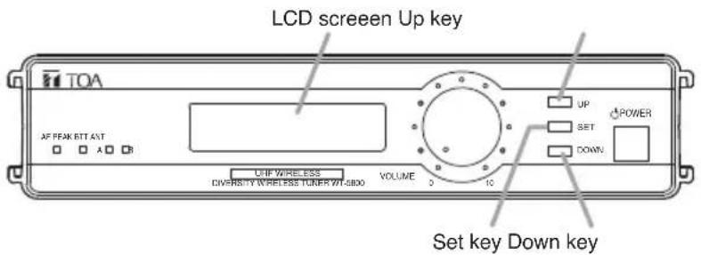
Setting items displayed on the LCD screen
The display cycles through the indications "SET CHANNEL," "SET BANK," "SET SQ LEVEL," "SET LCD POWER," CHANNEL CHECK," "RF CHECK," "About Model" and "Exit" with each depression of the Up key, or the Down key for the reverse action.
6.2.1. Channel (frequency) setting
Step 1. Press the Set key for about a second until the screen displays the first setting item "SET CHANNEL." The unit is placed in setting mode.
Step 2. Press the Set key, and the screen displays the currently-set channel and frequency with the prefix ">=" indication. (Example: >=8: 805.000 MHz)
Step 3. Select the desired channel/frequency with the Up or Down key. The display cycles through the contents with each depression of the Up or Down key.
Step 4. Press the Set key to register the selected channel/frequency. This terminates the Channel (frequency) setting, and the display returns to the "SET CHANNEL" indication.
Note
When leaving the original channel/frequency unchanged, select "Exit" with Up or Down key and press the Set key. Then, the display returns to the "SET CHANNEL" indication.
Step 5. When any other setting is not needed, select "Exit" with the Up or Down key and press the Set key. The unit returns to the normal operating state.
6.2.2. Bank number/frequency setting
Step 1. Press the Set key for over a second to place the unit in setting mode.
Step 2. Select the setting item "SET BANK" with the Up or Down key.
Step 3. Press the Set key again, and the screen displays the currently-set Bank number and frequency with the prefix ">=" indication. (Example: >=1:7 805.000 MHz)
Step 4. Select the desired Bank number/frequency with the Up or Down key. The display cycles through the contents with each depression of the Up or Down key.
Step 5. Press the Set key to register the selected Bank number/frequency. This terminates the Bank number/frequency setting, and the display returns to the "SET BANK" indication.
Note
When leaving the original Bank number/frequency unchanged, select "Exit" with Up or Down key and press the Set key. Then, the display returns to the "SET BANK" indication.
Step 6. When any other setting is not needed, select "Exit" with the Up or Down key and press the Set key. The unit returns to the normal operating state.
6.2.3. Squelch level setting
The WT-5800/5805 tuner has the squelch function that virtually eliminates ambient noise and unwanted audio signals from other wireless microphone systems by silencing the output when the signal received is lower than a certain level of signal strength. This strength level can be varied by means of the squelch control.
Step 1. Press the Set key for over a second to place the unit in setting mode.
Step 2. Select the setting item "SET SQ LEVEL" with the Up or Down key.
Step 3. Press the Set key, and the squelch level adjustment display "RF >" appears on the screen.
Step 4. Set the squelch level referring to the on-screen bar-graph meter (6 segments) which can be changed with Up or Down key.
Step 5. Press the Set key to register the selected value.
This terminates the Squelch level setting, and the display returns to the "SET SQ LEVEL" indication.
Note
When leaving the original value unchanged, select "Exit" with Up or Down key and press the Set key. Then, the display returns to the "SET SQ LEVEL" indication.
Step 6. When any other setting is not needed, select "Exit" with the Up or Down key and press the Set key. The unit returns to the normal operating state.
The squelch level ranges from "0" to "6." The wireless tuner's sensitivity is the highest and radio signals can be received in wide areas when the "0" level is selected, while the "6" level makes the sensitivity the lowest, limiting signal reception only to narrow areas.
The wireless microphone's signal transmission distance varies largely depending on its ambient conditions. The table below provides guidelines on the squelch level vs. transmission distance.
| Squelch Level 0123456 | |||||||
| Transmission Distance (%) 100857050302015 | |||||||
Note: Transmission distance is a relative ration with respect to 100% at "0" level.
Tips
- Set the control to the "0" position in locations free from interference.
- Set the control to the position that does not cause any reception loss of wireless microphone signals.
6.2.4. LCD backlight brightness adjustment
Step 1. Press the Set key for over a second to place the unit in setting mode.
Step 2. Select the setting item "SET LCD POWER" with the Up or Down key.
Step 3. Press the Set key, and the brightness adjustment display appears on the screen.
Step 4. Select either "HIGH (Bright)" or "LOW (Dark)" with the Up or Down key.
Step 5. Press the Set key to register the selected brightness level.
This terminates the Brightness setting, and the display returns to the "SET LCD POWER" indication.
Step 6. When any other setting is not needed, select "Exit" with the Up or Down key and press the Set key. The unit returns to the normal operating state.
6.2.5. Channel detection
Step 1. Press the Set key for over a second to place the unit in setting mode.
Step 2. Select the setting item "CHANNEL CHECK" with the Up or Down key.
Step 3. Press the Set key.
Channel detection begins, and an idle channel number with frequency is displayed on the screen. When 2 or more idle channels exist, each of them can be displayed in sequence with the Up or Down key. If no idle channel is detected, "Vacant CHANNEL doesn't exist" is displayed.
Step 4. Press the Set key to register the selected channel.
This terminates the Channel detection, and the display returns to the "CHANNEL CHECK" indication.
Note
When leaving the original channel unchanged, select "Exit" with Up or Down key and press the Set key. Then, the display returns to the "CHANNEL CHECK" indication.
Step 5. When any other setting is not needed, select "Exit" with the Up or Down key and press the Set key.
The unit returns to the normal operating state.
6.2.6. RF check
Step 1. Adjust the volume control to decrease the volume. (Big noise is output if the unit is placed in RF check mode when no signal is present.)
Step 2. Press the Set key for over a second to place the unit in setting mode.
Step 3. Select the setting item "RF CHECK" with the Up or Down key.
Step 4. Press the Set key to check idle channels by hearing sound.
The receiving antenna alternates between Antenna A and Antenna B with each depression of the Up or Down key.
Step 5. Press the Set key again after check completion.
This exits the RF check mode, and the display returns to the "RF CHECK" indication.
Step 6. When any other setting is not needed, select "Exit" with the Up or Down key and press the Set key.
The unit returns to the normal operating state.
6.2.7. Confirming firmware version
Step 1. Press the Set key for over a second to place the unit in setting mode.
Step 2. Select the setting item "About Model" with the Up or Down key.
Step 3. Press the Set key to display the firmware version.
Step 4. Press the Set key again to exit the firmware display mode.
The display returns to the "About Model" indication.
Step 5. When any other setting is not needed, select "Exit" with the Up or Down key and press the Set key.
The unit returns to the normal operating state.
7. HOW TO CHECK AND DEAL WITH INTERFERENCE
[Order of Actions (Action Flowchart)]
![TOA WT-5805 - [Order of Actions (Action Flowchart)] - 1](/content/2026/05/760435/images/9338c18d030ddf44a5a16c1175a7ce33601bd49427d1908c43de8c9506921a05.jpg)
flowchart
graph TD
    A["Place unit in RF check mode and check signal condition of the channel."] --> B{Any interference?}
    B -->|No| C["Use as is."]
    B -->|Yes| D["Change bank/channel numbers to those of idle channels."]
    D --> E["It is convenient to use "CHANNEL CHECK" when selecting idle bank/channel numbers."]
    E --> F["Place unit in RF check mode for a while and check signal condition of the channel."]
    F --> G{Any interference?}
    G -->|No| H["Use as is."]
    G -->|Yes| I["Most interference can be avoided by operations above. If interference is still encountered, select channel having relatively less interference using RF check switch, then continue following operations."]
    I --> J["Adjust squelch control to limit service area."]
    J --> K{Any interference?}
    K -->|No| L["Use as is."]
    K -->|Yes| M["When radio interference is still encountered, consult shop from where unit was purchased."]
    L --> N["Refer to p. 8 "6.2.6. RF check.""]
    M --> O["Refer to p. 6 "6.2.2. Bank number/frequency setting.""]
    O --> P["Refer to p. 8 "6.2.5. Channel detection.""]
    P --> Q["Refer to p. 7 "6.2.3. Squelch level setting.""]
8. CONNECTION EXAMPLES
Be sure to connect at least two receiving antennas (one each for Channels A and B).
[Example 1]
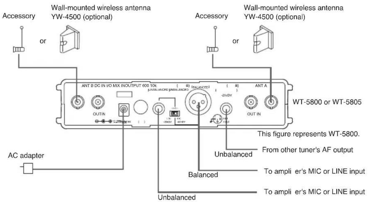
[Example 2]

9. RACK MOUNTING
- When mounting one WT-5800/5805 unit, use an optional mounting kit MB-WT3.

*1 Component parts of the MB-WT3.
- When mounting two WT-5800/5805 units, use an optional mounting kit MB-WT4.

*2 Component parts of the MB-WT4.
10. SPECIFICATIONS
| Model No. WT-5800 WT-5805 | |
| Power Source AC mains (Supplied AC adapter must be used) | |
| Power Consumption 250 mA (12 V DC) 200 mA (12 V DC) | |
| Receiving Frequency 506 | -867 MHz(506 - 538 MHz and 576 - 606 MHz for USA/Canada, 614 - 698 MHz for Brazil, 748.3 - 757.7 MHz and 803.3 - 805.7 MHz for Thailand, 865 - 867 MHz for India) |
| Channel Selectable 64 selectable frequencies | |
| Receiving System Double super-heterodyne | |
| Diversity System Space diversity (true diversity) Space diversity | |
| Mixing Output MIC/LINE (selectable): -60 dB *1 (MIC)/-20 dB*1 (LINE), 600 ΩPhone jack (unbalanced), 600 Ω XLR-3-32 type connector (balanced) | |
| Mixing Input -20 dB | *1, 10 kΩ, unbalanced, phone jack |
| Antenna Input | 75 Ω, BNC (phantom powering for antenna), 9 V DC, 30 mA (max) |
| Antenna Output | 75Ω, BNC (Gain 0 dB) |
| Receiving Sensitivity | 90 dB or more, Signal to Noise ratio (20 dBμV input, 40 kHz deviation) |
| Squelch Sensitivity | 16 - 40 dBμV variable |
| Squelch System | Using together of noise SQ, carrier SQ and tone SQ |
| Tone Frequency | 32.768 kHz |
| Indicator | Audio (6 steps), RF (6 steps), ANT A/B, Audio (peak), Battery alarm |
| Channel Check | Usable frequencies scanning |
| Signal to Noise Ratio | 110 dB or more (A-weight, unbalanced output) |
| Harmonic Distortion | 1% or less (typical) |
| Frequency Response | 100 Hz - 15 kHz, ±3 dB |
| Operating Temperature | -10°C to +50°C (14°F to 122°F) |
| Operating Humidity | 30 % to 85 %RH |
| Finish | Resin, black |
| Dimensions | 210 (w) x 44 (h) x 205.1 (d) mm (8.27" x 1.73" x 8.07") |
| Weight | 700 g (1.54 lb) |
^*1 0 dB = 1 V
Note: The design and specifications are subject to change without notice for improvement.
- Accessories
AC adapter ^*2 1
*2 No AC adapter is supplied with the version B02ER or C04ER.
- Optional products
Mounting bracket kit: MB-WT3 (for rack mounting one WT-5800/5805 unit) MB-WT4 (for rack mounting two WT-5800/5805 units)
natural_image
Line drawing of a rectangular electronic device with control panel and buttons (no text or symbols)INHALTSVERZEICHNIS
9. Antenneneingang A, B (75 Ω, BNC)
natural_image
Line drawing of a rectangular electronic device with control panel and buttons (no text or symbols)SOMMAIRE
- CONSEILS DE SECURITE 26
- GENERAL DESCRIPTION GENERALE .. 27
- CARACTERISTIQUES ...... 27
- PRECAUTIONS D'USAGE 28
-
NOMENCLATURE ET FONCTIONS
Face avant .... 28 Face arrière .... 29 -
FONCTIONNEMENT
natural_image
Line drawing of a rectangular electronic device with control panel and buttons (no text or symbols)ÍNDICE
natural_image
Line drawing of a rectangular electronic device with control panel and buttons (no text or symbols)ÍNDICE
- PRECAUÇÕES DE SEGURANÇA ..... 50
- DESCRIÇÃO GERAL 51
- CARACTERÍSTICAS 51
- PRECAUÇÕES RELATIVAS AO MANUSEIO . 52
- NOMENCLATURA E FUNÇÕES ..... 52
- OPERAÇÃO 53
4. PRECAUÇÕES RELATIVAS AO MANUSEIO
natural_image
Line drawing of a rectangular electronic device with control panel and ports (no text or symbols)目录
9. 天线输入 A,B
输入:75 Ω,BNC
通过按Up和Down键,循环显示下列项目:"SET CHANNEL," "SET BANK," "SET SQ LEVEL," "SET LCD POWER," CHANNEL CHECK," "RF CHECK," "About Model" 和 "Exit"。
6.2.1. 频道(频率)设置
Any modification to the unit, unless expressly approved by TOA Electronics, Inc. could void your authority to operate the equipment.
DECLARATION OF CONFORMITY
TOA Electronics, Inc
1 Harmon Plaza, Suite 602 Secaucus, New Jersey 07094, USA TEL 650-452-1200
declare under our sole responsibility that the product
WIRELESS TUNER WT-5800, WT-5805 WT-5810, WT-S200,
WT-4800, WT-4810 and WT-4820
WIRELESS TUNER UNIT WTU-4800
comply with Part 15 of FCC Rules.
Operation is subject to the following conditions: (1) this device may not cause harmful interference, and (2) this device must accept any interference received, including interference that may cause undesired operation.

TOA
DECLARATION OF CONFORMITY
We: TOA Electronics Europe GmbH
as the authorised representative of the
Manufacturer:
TOA Corporation
7-2-1, Minatojima-nakamachi, Chuo-ku, Kobe, Japan 650-0046
declare, under our sole responsibility, that the product
Product Name: WIRELESS TUNER, WIRELESS TUNER UNIT
Model Number: WT-5800, WT-5805, WT-5810, WT-4820, WT-5100, WTU-4800
conforms with following specifications:
RED: EN 301 489-1 V2.2.0 (2017-03)
EN 301 489-9 V2.1.1 (2017-03)
EN 300 422-1 V2.1.2 (2017-01)
EN 62368-1: 2014 + A11: 2017
RoHS: EN 50581: 2012
The product herewith complies with the requirements of the EU directives:
2014/53/EU relating to the radio equipment (RED),
2011/65/EU relating to the restrictions of hazardous substances (RoHS).
Remark:
This Declaration of Conformity replaces all previous ones of the above model(s).

Hamburg, 13 June 2017
(place, date)

T. Sakata, Managing Director
(authorised signature)
The Technical Construction File (TCF) is kept at the UK office:
TOA Corporation (UK) Ltd; Unit 7 & 8, The Axis Centre, Cleeve Road, Leatherhead, Surrey, KT22
7RD, United Kingdom
Tel.: +44 (0) 870 774 0987; Fax: +44 (0) 870 777 0839; URL: www.toa.co.uk
German Office:
TOA Electronics Europe GmbH, Süderstraße 282, 20537 Hamburg, Germany
Tel: +49 / (0)40 / 25 17 19-0, Fax: +49 / (0)40 / 25 17 19-98 URL: www.toa.eu
COMPLIANCE STATEMENT TO
WT-4820, WTU-4800, WT-5100, WT-5800, WT-5805, WT-5810
URL: www.toa.eu
| AT BE CH DE | ÖsterreichBelgienSchweizDeutschland | Hiermit erklärt TOA Electronics Europe GmbH die Übereinstimmung des Empfängers / Empfangsmoduls mit den grundlegenden Anforderungen und den anderen relevanten Festlegungen der Richtlinie 2014/53/EU.(verantwortlich für die Schweiz: GoWild (Zug); URL: http://www.gowild.ch) |
| BE CH FR LU | BelgiqueSuisseFranceLuxembourg | Par la présente TOA Electronics Europe GmbH déclare que l'appareil récepteur / module de réception est conforme aux exigences essentielles et aux autres dispositions pertinentes de la directive 2014/53/UE.(CH: GoWild (Zug); URL: http://www.gowild.ch) |
| BE NL | BelgiëNederland | Hierbij verklaart TOA Electronics Europe GmbH dat deze ontvanger / ontvangstmodule in overeenstemming is met de essentiële eisen en de andere relevante bepalingen van richtlijn 2014/53/EU. |
| BG | Държава | С настоящото TOA Electronics Europe GmbH, декларира, че този приемник / тунер модул е в съответствие със съществените изисквания и другите приложими разпоредби на Директива 2014/53/EC. |
| CY | Купроσ | Н TOA Electronics Europe GmbH, δηλώνει ότι ο δέκτης σημάτων/radioфωνικός δέκτης συνάδει με τις βασικές απαιτήσεις και άλλες σχετικές διατάξεις της Οδηγίας 2014/53/EE. |
| CZ | Česká republika | TOA Electronics Europe GmbH tímto prohlašuje, že tento přijímač / modul tuneru je ve shodě se základními požadavky a dalšími příslušnými ustanoveními směrnice 2014/53/EU. |
| DK | Danmark | Undertegnede TOA Electronics Europe GmbH erklærer herved, at følgende udstyr Modtager / Modtager Modul overholder de væsentlige krav og øvrige relevante krav i direktiv 2014/53/EU. |
| EE | Eesti | Käesolevaga TOA Electronics Europe GmbH, teatab, et see vastuvõtja / tuuner moodul on vastavus olulistele nõuetele ja teistele asjakohastele sätetele direktiivi 2014/53/EL. |
| ES | España | TOA Electronics Europe GmbH declara que el receptor / sintonizador inalámbrico cumple con los requisitos esenciales y otras disposiciones aplicables o exigibles en la Directiva 2014/53/UE. |
| FI | Suomi / Finland | TOA Electronics Europe GmbH vakuuttaa täten että tämä vastaanotin / viritinmoduli on direktiivin 2014/53/EU oleellisten vaatimusten ja sitä koskevien direktiivin muiden ehtojen mukainen. |
| UK IE | United Kingdom Eire | Hereby, TOA Electronics Europe GmbH, declares that this receiver / tuner module is in compliance with the essential requirements and other relevant provisions of Directive 2014/53/EU. |
| GR | Ελλαδα | Με την παρούσα η εταιρεία TOA Electronics Europe GmbH δηλώνει ότι ο ραδιοφωνικός δέκτης/ μονάδα δέκτη συμμορφώνεται με τις ουσιώδεις απαιτήσεις και τις λοιπές σχετικές διατάξεις της οδηγίας 2014/53/EE. |
| HR | Hrvatska | Ovime, TOA Electronics Europe Gmbh, izjavljuje, da je ovaj prijemnik/modul prijemnika u skladu s osnovnim zahtijevima i relevantnim odredbama direktive 2014/53/EU. |
| HU | Magyarország | A TOA Electronics Europe GmbH ezennel kijelenti, hogy ez a vevőkészülék megfelel az 2014/53/EU Irányelv alapvető követelményeinek és egyéb vonatkozó rendelkezéseinek. |
| ITCH | Italia Svizzera (Italian) | Con la presente TOA Electronics Europe GmbH dichiara che questo Ricevitore / Modulo sintonizzatore è conforme ai requisiti essenziali ed alle altre disposizioni pertinenti stabilite dalla direttiva 2014/53/UE. |
| LT | Lietuva | Šiuo, Toa Electronics Europe GmbH ", deklaruoja, kad šis imtuvas / imtuvas modulis atitinka esminius reikalavimus ir kitas susijusias nuostatas Direktyvos 2014/53/ES. |
| LV | Latvija | TOA Electronics Europe GmbH, deklarē, ka šis uztvērējs / raidītāja modulis atbilst būtiskajām prasībām un citiem ar to saistītajiem noteikumiem Direktīvā 2014/53/ES. |
| MT | Malta | TOA Electronics Europe GmbH tistqarr li r-ričevitur u t-tuner module (il-modulu li jagħżel il-frekwenzi) jissodisfaw l-obbligi necessarji u provvedimenti oħra relevant tad-direttiva 2014/53/UE. |
| NO | Norway (Norwegian) | TOA Electronics Europe GmbH erklærer herved, at denne mottagermodul / radio er i samsvar med de vesentlige egenskapene og øvrige relevante krav i direktiv 2014/53/EU. (N: Scandec Systemer AS, URL: www.scandecsystemer.no) |
| PL | Polska | My, TOA Electronics Europe GmbH, niniejszym deklarujemy, iż ten odbiornik/moduł tunera jest zgodny z zasadniczymi wymaganiami oraz innymi stosowanymi postanowieniami Dyrektywy 2014/53/UE. |
| PT | Portugal | TOA Electronics Europe GmbH declara que este Receptor / Sintonizador está conforme com os requisitos essenciais e outras disposições da Directiva 2014/53/UE. |
| RO | Romania | Prin aceasta TOA Electronics Europe GmbH declara ca acest modul receptor / tuner este in conformitate cu cerintele esentiale si cu alte prevederi relevante ale Directivei 2014/53/UE. |
| SE | Sverige (Swedish) | Härmed intygar TOA Electronics Europe GmbH att denna Mottagare / Radio modul står I överensstämmelse med de väsentliga egenskapskrav och övriga relevanta bestämmelser som framgår av direktiv 2014/53/EU. |
| SI | Slovenija | S tem, TOA Electronics Europe GmbH, izjavlja, da je ta sprejemnik / tuner modul v skladu z bistvenimi zahtevami in drugimi ustreznimi določbami Direktive 2014/53/EU. |
| SK | Štát | TOA Electronics Europe GmbH týmto prehlasuje, že tento prijímač/modul tunera je v zhode so základnými požiadavkami a d'alšími príslušnými ustanoveniami smernice 2014/53/EÚ. |
INTENDED USE OF WT-4820, WTU-4800, WT-5800, WT-5805, WT-5810
| AT BECH DE | Österreich Schweiz Deutschland | WICHTIGER HINWEIS! | Der Gebrauch dieses Funkempfängers für andere Zwecke als zum Empfang eines Tonsignals von einem passenden Funkmikrofon ist nicht zulässig.Dieses Gerät arbeitet auf in der europäischen Gemeinschaft (EU) nicht harmonisierten Frequenzen. Abhängig vom geografi schen Gebiet dürfen bestimmte Frequenzen legal mit oder ohne Autorisierung / individueller Lizenz entsprechend der beigefügten Frequenztabelle genutzt werden. |
| BE CH FR LU | Belgique Suisse France Luxembourg | AVIS IMPORTANT! | Ne pas utiliser les récepteurs HF pour une réception du signal audio provenant d' un appareil, autre que les microphones prévus à cet effet.Cet appareil utilise des fréquences d'émission qui ne sont pas harmonisées à travers la Communauté Européenne (EU). En fonction du lieu géographique certaines fréquences peuvent être utilisée de façon légale avec ou sans autorisation / licence individuelle comme décrit dans le tableau des fréquences. |
| BE NL | België Nederland | BELANGRIJKE AANWIJZING! | Het is niet toegestaan deze ontvanger te gebruiken voor enig ander doel dan het ontvangen van een audiosignaal van de bijbehorende draadloze microfoon.Dit apparaat maakt gebruik van frekwentiebanden welke in de Europesche Gemeenschap (EG) niet algemeen zijn toegestaan. Afhankelijk van de geografi sche ligging kan voor het legaal gebruik van een bepaalde frekwentie een vergunning nodig zijn, zoals is aangegeven in de frekwentietabel. |
| BG | Държава | ВАЖНО УТОЧНЕНИЕ! | Не е законно използването на този приемник за каквато и да е друга цел, освен приемането на аудио сигнали от предвидения негов безжичен микрофон. Това устройство може да работи в честототен диапазон, нехармонизиран с изискванията на Европейската Общност (EC). В зависимост от конкретното географско място, само определени честоти могат да бъдат използвани легално – със или без оторизация / индивидуална лицензия, както е посочено в таблицата с честотите. |
INTENDED USE OF WT-4820, WTU-4800, WT-5800, WT-5805, WT-5810
INTENDED USE OF WT-4820, WTU-4800, WT-5800, WT-5805, WT-5810
INTENDED USE OF WT-4820, WTU-4800, WT-5800, WT-5805, WT-5810
INTENDED USE OF WT-4820, WTU-4800, WT-5800, WT-5805, WT-5810
| LV | Latvija | SVARĪGAPIEZĪME! | Uztvērēju paredzētā izmantošanaIr aizliegts izmantot šo uztvērēju jebkuram citam nolūkam, kā saņemot audio signālu no atbilstoša bezvadu mikrofona.Šī iekārta izmanto frekvenču joslas, kas nav saskaņotas visā Eiropas savienībā (ES).Atkarībā no ğeogrāfiskā regiona tikai noteiktās frekvences var izmantot legāli, ar vai bez atļaujas vai individuālās licences, kā norādīts frekvenču tabulā. |
| MT | Malta | NOTA MPORTANTI! | Uzu tar-receiversMhux permess l-uzu ta’ dan ir-recievers, hlief biex jittrazmetti sinjal ‘audio’ lil microfonu tieghu. Kwalinkwe uzu ghal skop differenti, huwa llegali.Dan il-microphone jaghmel uzu minn frekwenzi li mhux ..... fl -Unjoni Ewropeja. F’certu zoni jistghu jigu ntuzati biss legalment certu frekwenzi bil- jew bla- awtorizzazzjoni jew licenzji li huma mhabbrin fuq il-‘frequency table’. |
| NO | Norway | VIKTIG MELDING! | Det er ulovlig å bruke denne mottakeren til noe annet formål enn å motta et lydsignal fra en tilhørende trådløs mikrofon.Denne enheten gjør bruk av frekvensbänd som ikke gjennomført er harmonisert i det Europeiske Fellesskap (EU). Avhengig av det geografi ske område kan noen frekvenser være tillatt brukt med eller uten autorisasjon / individuelle lisenser slik det er beskrevet i frekvenstabellen. |
| PL | Polska | WAŽNAINFORMACJA! | Używanie odbiornika bezprzewodowego w celu innym, niż odbiór sygnału audio ze sparowanego z nim nadajnika jest niezgodne z prawem.To urządzenie wykorzystuje pasma częstotliwości, które nie są zharmonizowane w obrębie Unii Europejskiej (UE). W zależności od lokalnych regulacji krajowych część częstotliwości może być niemożliwa do wykorzystania, lub też wymagać posiadania licencji, zgodnie z Krajową Tablicą Przeznaczeń Częstotliwości. |
INTENDED USE OF WT-4820, WTU-4800, WT-5800, WT-5805, WT-5810
| PT | Portugal | NOTA IMPORTANTE! | Este Receptor só pode receber sinal de audio do respectivo Microfone Emissor. Este equipamento utiliza bandas de frequência que não estão harmonizadas em toda a Comunidade Europeia (CEE). De acordo com a área geográfi ca, certas frequências podem ser usadas com ou sem autorização / licença individual, conforme está mencionada na lista de frequências. |
| RO | Romania | NOTA IMPORTANTA! | Este ilegala utilizarea acestui receptor in orice alt scop decat receptionarea unui semnal audio transmis de catre microfonul sau compatibil.Acest dispositiv utilizeaza benzi de frecventa care nu sunt armonizate in Comunitatea Europeana (EU). In functie de asezarea geografica, numai anumite frecvente pot fi utilizate legal cu sau fara autorizatie/ licenta individuala dupa cum se mentioneaza in tabelul de frecvente. |
| SE | Sverige | VIKTIG ANMÄRKNING! | Det är illegalt att använda denna mottagare för något annat ändamål än att ta emot en audiosignal från dess tillhörande trådlösa mikrofon.Denna apparat utnyttjar frekvensband som inte överensstämmer med varandra inom hela Eyropeiska Gemenskapen (EG). Beroende på geografi skt område kan vissa frekvenser användas legalt med eller utan tillständ/ individuell licens enligt frekvensplanen. |
| SI | Slovenija | POMEMBNO! | Prepovedana je vsakršna uporaba sprejemnika v druge namene kot sprejemanje avdio signala pripadajočega brezžičnega mikrofona.Ta naprava omogoča uporabo frekvenčnih pasov, ki niso usklajeni v vsej Evropski skupnosti (EU). Glede na geografsko območje se lahko legalno uporabljajo samo določene frekvence z ali brez dovoljenja, kot je navedeno v frekvenčni tabeli. |
INTENDED USE OF WT-4820, WTU-4800, WT-5800, WT-5805, WT-5810
- TABLE OF CONTENTS
- SAFETY PRECAUTIONS
- Safety Symbol and Message Conventions
- WARNING
- When Installing the Unit
- When the Unit is in Use
- CAUTION
- GENERAL DESCRIPTION
- FEATURES
- HANDLING PRECAUTIONS
- NOMENCLATURE AND FUNCTIONS
- Power switch
- AF peak lamp
- Battery alarm lamp
- Reception lamps
- LCD screen
- Volume control
- Up/Down keys
- Set key
- [Rear]
- Antenna input A, B
- Cable hanger
- DC input jack
- I/O port
- AF output
- AF output level selector
- 16.AFoutput
- AF mixing input
- OPERATION
- Basic Operation
- Function Settings
- Setting items displayed on the LCD screen
- Channel (frequency) setting
- Note
- Bank number/frequency setting
- Squelch level setting
- Tips
- LCD backlight brightness adjustment
- Channel detection
- RF check
- Confirming firmware version
- HOW TO CHECK AND DEAL WITH INTERFERENCE
- [Order of Actions (Action Flowchart)]
- CONNECTION EXAMPLES
- RACK MOUNTING
- SPECIFICATIONS
- - Accessories
- - Optional products
- INHALTSVERZEICHNIS
- Antenneneingang A, B (75 Ω, BNC)
- SOMMAIRE
- ÍNDICE
- PRECAUÇÕES RELATIVAS AO MANUSEIO
- 目录
- 天线输入 A,B
- 频道(频率)设置
- DECLARATION OF CONFORMITY
- COMPLIANCE STATEMENT TO
- WT-4820, WTU-4800, WT-5100, WT-5800, WT-5805, WT-5810
- INTENDED USE OF WT-4820, WTU-4800, WT-5800, WT-5805, WT-5810
Brand : TOA
Model : WT-5805
Category : Receiver