
Obey 3 - Remote control Chauvet - Free user manual and instructions
Find the device manual for free Obey 3 Chauvet in PDF.


| Product type | Remote control for DMX lighting |
| Brand | Chauvet |
| Model | Obey 3 |
| Power supply | 12 V DC, 500 mA (adaptor included 100-240 V AC / 12 V DC 1 A) |
| Dimensions (L × W × H) | 210 × 140 × 52 mm |
| Weight | 0.9 kg |
| DMX protocol | DMX-512 USITT |
| DMX output | XLR 3-pin female connector |
| Controllable DMX channels | 512 channels |
| Main functions | Presets, Chases, Macros, Strobe, Blackout, Manual RGB, Sound activation |
| Strobe frequency | 0 to 33 Hz |
| Use | Indoor only |
| Maximum ambient temperature | 40 °C |
| Maintenance and cleaning | Unplug before cleaning. Use a vacuum cleaner and a soft cloth with glass cleaner or isopropyl alcohol. Clean external surfaces every 30-60 days. |
| Safety instructions | Do not expose to moisture. Do not connect to a dimmer. Unplug when not in use. Maintain at least 50 cm of ventilation. |
| Package contents | 1 × Obey 3, 1 × power supply, 1 × warranty card, 1 × user manual |
| Warranty | 2-year limited warranty |
| Manufacturer | Chauvet (USA) |
| Technical support | (844) 393-7575 (USA) or contact the dealer |
Frequently Asked Questions - Obey 3 Chauvet
User questions about Obey 3 Chauvet
0 question about this device. Answer the ones you know or ask your own.
Ask a new question about this device
Download the instructions for your Remote control in PDF format for free! Find your manual Obey 3 - Chauvet and take your electronic device back in hand. On this page are published all the documents necessary for the use of your device. Obey 3 by Chauvet.
USER MANUAL Obey 3 Chauvet
CHAUVET 3
TABLE OF CONTENTS
1. BEFORE YOU BEGIN....7
WHAT IS INCLUDED....7
UNPACKING INSTRUCTIONS 7
MANUAL CONVENTIONS 7
ICONS 7
SAFETY INSTRUCTIONS 8
2. INTRODUCTION 9
PRODUCT OVERVIEW....9
3. SETUP 10
AC POWER....10
MOUNTING....10
Orientation....10
Installation 10
4. OPERATING INSTRUCTIONS....11
OPERATING MODES....11
Preset Operation....11
Chases Operation 11
Macro Operation 11
OPERATING FUNCTIONS....12
Strobe....12
Blackout....12
Manual RGB 12
Sound 12
5. APPENDIX 13
DMX PRIMER 13
GENERAL MAINTENANCE....13
FIXTURE LINKING....14
Data Cabling 14
DMX Data Cable 14
Cable Connectors 14
3-Pin to 5-Pin Conversion Chart....15
Setting up a DMX Serial Data Link....15
SETTING THE STARTING ADDRESS....16
GENERAL TROUBLESHOOTING....16
RETURNS PROCEDURE 16
CLAIMS 17
TECHNICAL SPECIFICATIONS 17
CONTACT US....18
CONVENTIONS MANUELLES ....31
SIGLES 31
CONSIGNES DE SÉCURITÉ 32
- INTRODUCTION ...... 33
VUE D'ENSEMBLE DU PRODUIT 33
- CONFIGURATION....34
ALIMENTATION CA 34
MONTAGE....34
Orientation 34
Installation 34
- INSTRUCTIONS D'UTILISATION .... 34
MODES DE FONCTIONNEMENT 35
INTRODUCTION AU DMX 37
ENTRETIEN GENERAL....37
CHAINAGE DES APPAREILS 38
KONVENTIONEN DES HANDBUCHS....43
SYMBOLE 43
Kabelanschlüsse....50
NEEM CONTACT OP....67
The information and specifications contained in this document are subject to change without notice. Chauvet assumes no responsibility or liability for any errors or omissions that may appear in this manual.
© Copyright 2017 Chauvet. All rights reserved
Printed in P.R.C.
Electronically published by Chauvet in the United States of America
ÿ 1 x Obey 3
ÿ 1 x Power supply
ÿ 1 x Warranty Card
ÿ 1 x User Manual
Unpacking Instructions
Immediately upon receiving a fixture, carefully unpack the carton, check the contents to ensure that all parts are present, and have been received in good condition. Notify the shipper immediately and retain packing material for inspection if any parts appear damaged from shipping or the carton itself shows signs of mishandling. Save the carton and all packing materials. In the event that a fixture must be returned to the factory, it is important that the fixture be returned in the original factory box and packing.
Manual Conventions
Chauvet manuals use the following conventions to differentiate certain types of information from the regular text.
| CONVENTION | MEANING |
| [10] A DIP switch to be configured | |
| A key to be pressed on the fixture's control panel | |
| 1-512 A range of values | |
| 50/60 | A set of values of which only one can be chosen |
| Settings | A menu option not to be modified (for example, showing the operating mode/current status) |
| MENU > Settings | A sequence of menu options to be followed |
| ON | A value to be entered or selected |
Icons
This manual uses the following icons to indicate information that requires special attention on the part of the user.
| ICONS | MEANING |
 | This paragraph contains critical installation, configuration or operation information. Failure to comply with this information may render the fixture partially or completely inoperative, cause damage to the fixture or cause harm to the user. |
 | This paragraph contains important installation or configuration information. Failure to comply with this information may prevent the fixture from functioning correctly. |
 | This paragraph reminds you of useful, although not critical, information. |
Safety Instructions

Please read these instructions carefully. It includes important information about the installation, usage and maintenance of this product.
- Please keep this User Manual for future consultation. If you sell the unit to another user, be sure that they also receive this instruction booklet.
• Always make sure that you are connecting to the proper voltage, and that the line voltage you are connecting to is not higher than that stated on the decal or rear panel of the fixture. - This product is intended for indoor use only! To prevent risk of fire or shock, do not expose fixture to rain or moisture.
• Make sure there are no flammable materials close to the unit while operating. - The unit must be installed in a location with adequate ventilation, at least 20 in (50 cm) from adjacent surfaces. Be sure that no ventilation slots are blocked.
• Maximum ambient temperature (Ta) is 104 °F (40 °C). Do not operate fixture at temperatures higher than this. - In the event of a serious operating problem, stop using the unit immediately. Never try to repair the unit by yourself. Repairs carried out by unskilled people can lead to damage or malfunction. Please contact the nearest authorized technical assistance center.
• Never connect the device to a dimmer pack. - To eliminate wear and improve its lifespan, during periods of non-use completely disconnect from power via breaker or by unplugging it.
- Make sure the power cord is never crimped or damaged.
2. INTRODUCTION
Product Overview
![graph TD A["Chauvet"] --> B["PreSET COLORS"] A --> C["Red"] A --> D["Green"] A --> E["Blue"] A --> F["Sensitivity"] A --> G["Strobe Button"] A --> H["Blackout Button"] A --> I["Manual RGB Button"] A --> J["Sound Button"] A --> K["Master Dimmer/Blue Fader"] A --> L["Fade/Speed/ Strobe/Green Fader"] A…](/content/2026/05/760180/images/83e769e0cc2f83200282c5c9cb3ed22929ea98d6f2f86478fd062f179c6a1b13.jpg)
3. SETUP
AC Power
This fixture runs on 12 VDC, 500 mA. Before powering on the unit, make sure the power supply voltage to which you are connecting it is correct.

• Always connect the fixture to a switched circuit. Never connect the fixture to a rheostat (variable resistor) or dimmer circuit, even if the rheostat or dimmer channel is used only as a 0 to 100% switch.
To eliminate wear and improve its lifespan, during periods of non-use completely disconnect from power via breaker or by unplugging it.
To determine the power requirements for a particular fixture, see the label affixed to the back plate of the fixture or refer to the fixture's specifications chart. A fixture's listed current rating indicates its average current draw under normal conditions.
Mounting
Orientation
The Obey 3 may be mounted in any safe position, provided there is adequate room for ventilation.
Installation
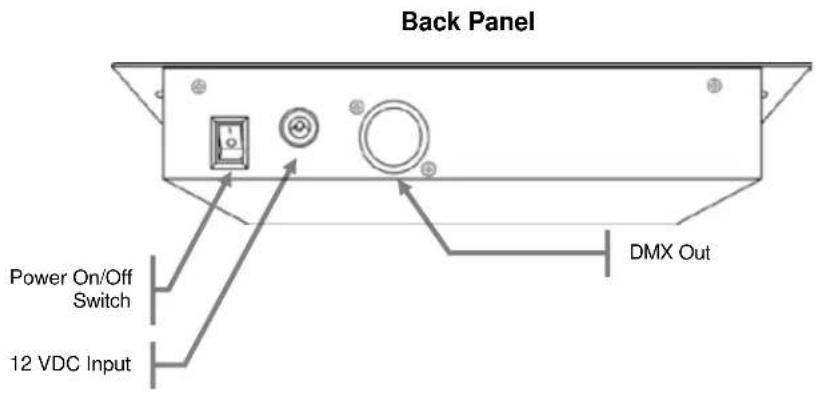
Please see the drawing below, which shows the back of the controller. It details the dimensions for mounting. This will aid in placing the holes for installation.

4. OPERATING INSTRUCTIONS
Operating Modes Preset Operation
This controller has preset color macros. There are nine color macros to choose from, which may be accessed using the nine preset buttons. Please see the instructions below for this operation.
- Press
until the appropriate LED indicator lights. - Adjust the Fade/Speed/Strobe/Green Fader to the desired level to set the Fade Time.
- Adjust the Master Dimmer/Blue Fader to the desired level.
- Select one of the nine preset color macros.
- The Fade time and dimming may now be readjusted.

Please be sure that the Strobe, Blackout, and Manual RGB functions are not overriding the controls.
Sound will not function in Preset Mode.
Chases Operation
This controller has preset color chases, which will change between one color and another. There are several color combinations to choose from. Please see the instructions below for this operation.
- Press
until the appropriate LED indicator lights. - Adjust the Fade/Speed/Strobe/Green Fader to the desired level to set the Fade Time.
- Adjust the Master Dimmer/Blue Fader to the desired level.
- Using the Chases/Macro/Red Fader, select one of the color combinations.
- The Fade time and dimming may now be readjusted.

There are several preset color combinations that may be discovered by moving the Chases/Macro/Red Fader through the full range of movement.

Please be sure that the Strobe, Blackout, and Manual RGB functions are not overriding the controls.

Sound will function in Preset Mode.
Macro Operation
This controller has preset color macros. This is a static color selection, meaning that no chasing, movement, or color flows of any kind will occur. There are several color macros to choose from, which may be accessed using the Chases/Macros Fader. Please see the instructions below for this operation.
- Press
until the appropriate LED indicator lights. - Adjust the Fade/Speed/Strobe/Green Fader to the desired level.
- Adjust the Master Dimmer/Blue Fader to the desired level.
- Using the Chases/Macro/Red Fader, select one of the color macros.
- The Fade time and dimming may now be readjusted.

Please be sure that the Strobe, Blackout, and Manual RGB functions are not overriding the controls.
Sound will not function in Preset Mode.
Operating Functions
Strobe
This controller has multiple functions for the 3 faders. One of the functions for the middle fader (Fade/Speed/Strobe/Green) is the strobe function. Please see the instructions below for this operation.
- Press
until the appropriate LED indicator lights. - Adjust the fader to the desired level.
- In order to return to the desired mode, press
until the appropriate LED indicator is off.

This function may be activated while operating in any other mode (preset, chases, macro).

In order to deactivate this function, the mode must be entered, and the fader must be set to 0.1M (fully down). Then, deactivate
Blackout
This controller has a dedicated blackout button. This button works in conjunction with the Fade/Speed/Strobe/Green fader. Please see the instructions below for this operation.
- Adjust the Fade/Speed/Strobe/Green fader to the desired value to determine how quickly the lights will fade out.
- Press
until the appropriate LED indicator lights.

The blackout function will also work with the Fade/Speed/Strobe/Green fader when disabling the blackout.

The blackout function will not work when the controller is in manual RGB mode.
Manual RGB
This controller has the ability to manually choose a custom color combination by simply using the Red, Green, and Blue faders. However,
- Press
until the appropriate LED indicator lights. - Adjust the Red, Green, and Blue Faders to the desired levels.

You may press

Blackout will not work in Manual RGB function.

Fade/Speed will not work in Manual RGB function.
Sound
This controller has preset chases. These chases are normally triggered using the Speed fader. However, they can be triggered using the built-in microphone, as well. Please see the instructions below for this operation.
- Follow the instructions for working with chases in the appropriate section of this manual.
- Press
until the appropriate LED indicator lights. - Adjust the Sensitivity Fader to the desired level (turn clockwise to increase sensitivity).

You may press
5. APPENDIX
DMX Primer
There are 512 channels in a DMX connection. Channels may be assigned in any manner. A fixture capable of receiving DMX will require one or a number of sequential channels. The user must assign a starting address on the fixture that indicates the first channel reserved in the controller. There are many different types of DMX controllable fixtures and they all may vary in the total number of channels required. Choosing a start address should be planned in advance. Channels should never overlap. If they do, this will result in erratic operation of the fixtures whose starting address is set incorrectly. You can however, control multiple fixtures of the same type using the same starting address as long as the intended result is that of unison movement or operation. In other words, the fixtures will be slaved together and all respond exactly the same.
DMX fixtures are designed to receive data through a serial Daisy Chain. A Daisy Chain connection is where the DATA OUT of one fixture connects to the DATA IN of the next fixture. The order in which the fixtures are connected is not important and has no effect on how a controller communicates to each fixture. Use an order that provides for the easiest and most direct cabling. Connect fixtures using shielded two conductor twisted pair cable with three pin XLR male to female connectors. The shield connection is pin 1, while pin 2 is Data Negative (S-) and pin 3 is Data positive (S+).
General Maintenance
To maintain optimum performance and minimize wear, fixtures should be cleaned frequently. Usage and environment are contributing factors in determining frequency. As a general rule, fixtures should be cleaned at least twice a month. Dust build up reduces light output performance and can cause overheating. This can lead to reduced lamp life and increased mechanical wear. Be sure to power off fixture before conducting maintenance.
- Unplug fixture from power.
- Use a vacuum or air compressor and a soft brush to remove dust collected on external vents.
- Clean all glass when the fixture is at room temperature with a mild solution of glass cleaner or Isopropyl Alcohol and a soft lint free cotton cloth or lens tissue.
- Apply solution to the cloth or tissue and drag dirt and grime to the outside of the lens.
- Gently polish optical surfaces until they are free of haze and lint.
The cleaning of external optical lenses and/or mirrors must be carried out periodically to optimize light output. Cleaning frequency depends on the environment in which the fixture operates. Damp, smoky or particularly dirty surroundings can cause greater accumulation of dirt on the unit's optics. Clean with soft cloth using normal glass cleaning fluid. Clean the external optics at least every 20 days. Clean the fixture at least every 30/60 days.

Always dry the parts carefully after cleaning them.
Fixture Linking
You will need a serial data link to run light shows of one or more fixtures using a DMX controller or to run synchronized shows on two or more fixtures set to a master/slave operating mode. The combined number of channels required by all the fixtures on a serial data link determines the number of fixtures the data link can support.

Fixtures on a serial data link must be daisy chained in one single line. To comply with the EIA-485 standard, no more than 32 fixtures should be connected on one data link. Connecting more than 32 fixtures on one serial data link without the use of a DMX optically-isolated splitter may result in deterioration of the digital DMX signal.
Maximum recommended serial data link distance: 500 m (1640 ft)
Maximum recommended number of fixtures on a serial data link: 32
Data Cabling
To link fixtures together you must obtain data cables. You can purchase Chauvet certified DMX cables directly from a dealer/distributor or construct your own cable. If you choose to create your own cable please use data-grade cables that can carry a high quality signal and are less prone to electromagnetic interference.
DMX Data Cable
Use a Belden© 9841 or equivalent cable which meets the specifications for EIA RS-485 applications. Standard microphone cables cannot transmit DMX data reliably over long distances. The cable must have the following characteristics:
Type: shielded, 2-conductor twisted pair
Maximum capacitance between conductors: 30 pF/ft
Maximum capacitance between conductor and shield: 55 pF/ft
Maximum resistance: 20 ohms/1000 ft
Nominal impedance:
100 \~ 140 ohms
Cable Connectors
Cabling must have a male XLR connector on one end and a female XLR connector on the other end.
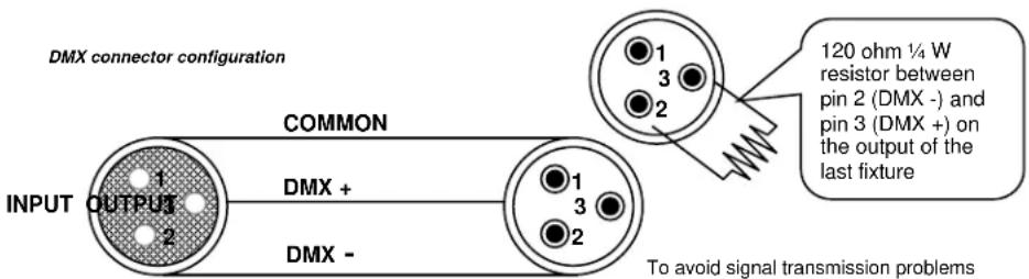
To avoid signal transmission problems and interference, it is always advisable to connect a DMX signal terminator.

Do not allow contact between the common and the fixture's chassis ground. Grounding the common can cause a ground loop, and your fixture may perform erratically. Test cables with an ohm meter to verify correct polarity and to make sure the pins are not grounded or shorted to the shield or each other.
3-Pin to 5-Pin Conversion Chart

If you use a controller with a 5-pin DMX output connector, you will need to use a 5-pin to 3-pin adapter. The chart below details a proper cable conversion:
3-PIN TO 5-PIN CONVERSION CHART
| Conductor | 3-Pin Female (Output) | 5-Pin Male (Input) |
| Ground/Shield | Pin 1 | Pin 1 |
| Data (-) signal | Pin 2 | Pin 2 |
| Data (+) signal | Pin 3 | Pin 3 |
| Not used | Pin 4 | |
| Not used | Pin 5 |
Setting up a DMX Serial Data Link
- Connect the (male) 3-pin connector side of the DMX cable to the output (female) 3-pin connector of the controller.
- Connect the end of the cable coming from the controller which will have a (female) 3-pin connector to the input connector of the next fixture consisting of a (male) 3-pin connector.
- Then, proceed to connect from the output as stated above to the input of the following fixture and so on.
Universal DMX Controller
![graph TD A["DMX OUT"] --> B["DMX IN"] B --> C["DMX OUT/DMX IN"] C --> D["DMX OUT/DMX IN"] D --> E["End"] style A fill:#f9f,stroke:#333 style B fill:#ccf,stroke:#333 style C fill:#cfc,stroke:#333 style D fill:#fcc,stroke:#333 note right of A: This drawing provides a general illustration of the DMX in…](/content/2026/05/760180/images/c4e2f09124f334bf13828cb250843304134235053722b728af2791aa95251adf.jpg)
Setting the Starting Address
This DMX mode enables the use of a universal DMX controller device. Each fixture requires a start address from 1\~512. A fixture requiring one or more channels for control begins to read the data on the channel indicated by the start address. For example, a fixture that uses six DMX channels and was addressed to start on DMX channel 100, would read data from channels: 100, 101, 102, 103, 104, and 105. Choose start addresses so that the channels used do not overlap, and note the start address selected for future reference.
If this is your first time addressing a fixture using the DMX control protocol, go to the Appendix section, and read the DMX Primer from the Chauvet website www.chauvetlighting.com. It contains very useful information that will help you understand its use.
General Troubleshooting
| SYMPTOM | POSSIBLE CAUSE(S) | POSSIBLE ACTION(S) |
| Breaker/Fuse keeps blowing | Excessive circuit loadShort circuit along the power wires | Check total load placed on the electrical circuit.Check for a short in the electrical wiring (internal and/or external). |
| Device does not power up | No powerLoose power cord | Check for power on Mains.Check power cord |
| Fixture is not responding to DMX | Wrong DMX addressingDamaged DMX cablesWrong polarity settings on the controllerLoose DMX cablesFaulty DMX interfaceFaulty Main PCB | Check Control Panel and unit addressingCheck DMX cablesCheck polarity switch settings on the controllerCheck cable connectionsReplace DMX inputReplace Main PCB |
| Loss of signal | Non DMX cablesBouncing signalsLong cable / Low level signalToo many fixturesInterference from AC wires | Use only DMX compatible cablesInstall terminator as suggested.Install amplifier right after fixture with strong signal.Install an optically coupled DMX splitter after unit #32.Keep DMX cables separated from power cables or black lights. |

If you still have a problem after trying the above solutions, please contact Chauvet Technical Support.
Returns Procedure
Returned merchandise must be sent prepaid and in the original packing; call tags will not be issued. Package must be clearly labeled with a Return Merchandize Authorization Number (RMA #). Products returned without the RMA # will be refused. Call Chauvet and request an RMA # prior to shipping the fixture. Be prepared to provide the model number, serial number and a brief description of the cause for the return. Be sure to pack fixture properly; any shipping damage resulting from inadequate packaging is the customer's responsibility. As a suggestion, proper UPS packing or double-boxing is always a safe method to use.
Chauvet reserves the right to use its own discretion to repair or replace product(s).

If you are given an RMA #, please include the following information on a piece of paper inside the box:
1) Your name
2) Your address
3) Your phone number
4) RMA #
5) A brief description of the symptoms
Claims
Damage incurred in shipping is the responsibility of the shipper; therefore, the damage must be reported to the carrier upon receipt of merchandise. It is the customer's responsibility to notify and submit claims with the shipper in the event that a fixture is damaged due to shipping. Any other claim for items such as missing component/part, damage not related to shipping, and concealed damage, must be made within seven (7) days of receiving merchandise
Technical Specifications
WEIGHT & DIMENSIONS
Length....5.5 in (140 mm)
Width....8.3 in (210 mm)
Height 2.1 in (52 mm)
Weight....2 lbs (0.9 kg)
POWER
Operating Range....DC 12 V, 500 mA max
Voltage Adapter (external: 100\~240 VAC; 50/60 Hz; 0.4 A input) (12 VDC; 1 A output) ...... Provided
THERMAL
Maximum ambient temperature....104 °F (40 °C)
CONTROL & PROGRAMMING
Strobe Rate 0–33 Hz
Data output ...... locking 3-pin XLR female socket
Data pin configuration pin 1 shield, pin 2 (-), pin 3 (+)
Protocols......DMX-512 USITT
ORDERING INFORMATION
Obey 3 Controller....OBEY3
WARRANTY INFORMATION
Warranty 2-year limited warranty
CONTACT Us
WORLD HEADQUARTERS
General Information
Address:5200 NW 108th Avenue
Sunrise, FL 33351
Voice: (954) 577-4455
Fax: (954) 929-5560
Toll free:(800) 762-1084
EUROPE
General Information
Brookhill Road Industrial Estate
Pinxton, Nottingham, UK
NG16 6NT
Voice: +44 (0)1773 511115
Fax: +44 (0)1773 511110
MEXICO
General Information
(Entrance by Calle 2)
Zona Industrial Lerma
Lerma, Mexico C.P. 52000
Voice: +52 (728) 690-2010
Technical Support
Voice: (844) 393-7575
Fax: (954) 756-8015
Email: Chauvetcs@chauvetlighting.com
World Wide Web www.chauvetlighting.com
Technical Support
Email: Eutech@chauvetlighting.eu
World Wide Web www.chauvetlighting.eu
Technical Support
Email: uktech@chauvetlighting.com
World Wide Web www.chauvetlighting.co.uk
Technical Support
Email: servicio@chauvet.com.mx
World Wide Web www.chauvet.com.mx
Visit the applicable website above to verify our contact information and instructions to request support. Outside the U.S., United Kingdom, Ireland, Mexico, or Benelux, contact the dealer of record.
1. ANTES DE EMPEZAR
Qué va incluido
Brookhill Road Industrial Estate
Pinxton, Nottingham, UK
NG16 6NT
Voz: +44 (0)1773 511115
Fax: +44 (0)1773 511110
MÉXICO
Información General

INFORMATIONS SUR LA GARANTIE
SIÈGE SOCIAL MONDIAL
Brookhill Road Industrial Estate
Pinxton, Nottingham, UK
NG16 6NT
Téléphone: +44 (0)1773 511115
Télécopie: +44 (0)1773 511110
Support Technique
E-mail: uktech@chauvetlighting.com
Site Web www.chauvetlighting.co.uk
MEXIQUE
Brookhill Road Industrial Estate
Pinxton, Nottingham, GB
NG16 6NT
Adres: 5200 NW 108th Avenue
Sunrise, FL 33351
Bandopname:(954) 577-4455
Fax: (954) 929-5560
Toll free: (800) 762-1084
EUROPE
Algemene Informatie
Adres: Av. Stokstraat 18
9770 Kruishoutem
Belgium
Bandopname: +32 9 388 93 97
Algemene Informatie
Adres: Unit 1C
Brookhill Road Industrial Estate
Pinxton, Nottingham, UK
NG16 6NT
Bandopname:+44 (0)1773 511115
Fax: +44 (0)1773 511110
MEXICO
Algemene Informatie
- TABLE OF CONTENTS
- BEFORE YOU BEGIN....7
- INTRODUCTION 9
- SETUP 10
- OPERATING INSTRUCTIONS....11
- APPENDIX 13
- CONTACT US....18
- NEEM CONTACT OP....67
- © COPYRIGHT 2017 CHAUVET. ALL RIGHTS RESERVED
- UNPACKING INSTRUCTIONS
- MANUAL CONVENTIONS
- ICONS
- SAFETY INSTRUCTIONS
- INTRODUCTION
- SETUP
- AC POWER
- MOUNTING
- ORIENTATION
- INSTALLATION
- OPERATING INSTRUCTIONS
- OPERATING MODES PRESET OPERATION
- CHASES OPERATION
- MACRO OPERATION
- OPERATING FUNCTIONS
- STROBE
- BLACKOUT
- MANUAL RGB
- SOUND
- APPENDIX
- DMX PRIMER
- GENERAL MAINTENANCE
- FIXTURE LINKING
- DATA CABLING
- DMX DATA CABLE
- CABLE CONNECTORS
- 3-PIN TO 5-PIN CONVERSION CHART
- SETTING UP A DMX SERIAL DATA LINK
- SETTING THE STARTING ADDRESS
- RETURNS PROCEDURE
- CLAIMS
- TECHNICAL SPECIFICATIONS
- WEIGHT & DIMENSIONS
- POWER
- THERMAL
- CONTROL & PROGRAMMING
- ORDERING INFORMATION
- WARRANTY INFORMATION
- CONTACT US
- WORLD HEADQUARTERS
- GENERAL INFORMATION
- EUROPE
- MEXICO
- TECHNICAL SUPPORT
- ANTES DE EMPEZAR
- QUÉ VA INCLUIDO
- MÉXICO
- INFORMACIÓN GENERAL
- INFORMATIONS SUR LA GARANTIE
- SIÈGE SOCIAL MONDIAL
- SUPPORT TECHNIQUE
- MEXIQUE
- ALGEMENE INFORMATIE
Brand : Chauvet
Model : Obey 3
Category : Remote control