/CZ S — Cooker — Mode d'emploi PDF")
KN3G65SA(W)/CZ S - Cooker INDESIT - Free user manual and instructions
Find the device manual for free KN3G65SA(W)/CZ S INDESIT in PDF.

| Product Type | Freestanding Gas Cooker with Electric Oven |
| Brand | Indesit |
| Model | KN3G65SA(W)/CZ S |
| Oven Volume | 59 L |
| Oven Interior Dimensions (WxHxD) | 39 x 34 x 41 cm |
| Lower Compartment Dimensions (WxHxD) | 42 x 23 x 44 cm |
| Hob Burners | 3 burners: Fast (R) 3.0 kW, Semi Fast (S) 1.9 kW, Auxiliary (A) 1.0 kW |
| Gas Types | LPG (G30/G31) and Natural Gas (G20) |
| Electrical Supply | 230 V ~ 50 Hz |
| Oven Cooking Modes | Baking, Convection, Fan Assisted, Grill, Fan Assisted Grill, Top Oven |
| Oven Temperature Range | 50°C to Max (approx. 250°C) |
| Thermostat Indicator Light | Yes, indicates when oven is heating |
| Electronic Timer | Yes, countdown timer up to 10 hours |
| Oven Light | Yes, internal light |
| Safety Devices | Flame failure safety device on hob burners, anti-tilt safety chain |
| Hob Ignition | Electronic ignition (push and turn knob) |
| Adjustable Feet | Yes, 4 adjustable feet for levelling |
| Included Accessories | Sliding grill rack, dripping pan, adjustable feet, safety chain kit |
| Oven Cleaning | Enamel interior, wipe clean with non-abrasive detergent; door glass removable for cleaning |
| Energy Efficiency Class | Not specified; convection and fan-assisted modes available |
Frequently Asked Questions - KN3G65SA(W)/CZ S INDESIT
User questions about KN3G65SA(W)/CZ S INDESIT
0 question about this device. Answer the ones you know or ask your own.
Ask a new question about this device
Download the instructions for your Cooker in PDF format for free! Find your manual KN3G65SA(W)/CZ S - INDESIT and take your electronic device back in hand. On this page are published all the documents necessary for the use of your device. KN3G65SA(W)/CZ S by INDESIT.
USER MANUAL KN3G65SA(W)/CZ S INDESIT
Operating Instructions COOKER AND OVEN
Contents
Operating Instructions,1
ARNING,2
Description of the appliance-Overall view,6
Description of the appliance-Control Panel,7
Installation,8
Start-up and use,12
Cooking modes,13
Precautions and tips,17
Care and maintenance,18
Assistance,18
HU
MagyarMagyar
Használati útmutató
tűzhely és a sütő
Tartalomjegyzék
WARNING: The appliance and its accessible parts become hot during use.
Care should be taken to avoid touching heating elements.
Children less than 8 years of age shall be kept away unless continuously supervised.
This appliance can be used by children aged from 8 years and above and persons with reduced physical, sensory or mental capabilities or lack of experience and knowledge if they have been given supervision or instruction concerning use of the appliance in a safe way and understand the hazards involved. Children shall not play with the appliance. Cleaning and user maintenance shall not be made by children without supervision.
WARNING: Unattended cooking on a hob with fat or oil can be dangerous and may result in fire.
NEVER try to extinguish a fire with water, but switch off the appliance and then cover flame e.g. with a lid or a fire blanket.
Do not use harsh abrasive cleaners or sharp metal scrapers to clean the oven door glass since they can scratch the surface, which may result in shattering of the glass.
The internal surfaces of the compartment (where present) may become hot.
Never use steam cleaners or pressure cleaners on the appliance.
Remove any liquid from the lid before opening it.
Do not close the glass cover (if present) when the gas burners or electric hotplates are still hot.
WARNING: Ensure that the appliance is switched off before replacing the lamp to avoid the possibility of electric shock.
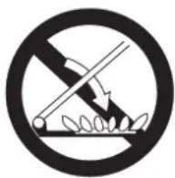
CAUTION: the use of inappropriate hob guards can cause accidents.
! When you place the rack inside, make sure that the stop is directed upwards and in the back of the cavity.
HU
FIGYELEM
Description of the appliance Overall view
1.Hob burner
2.Hob Grid
3. Control panel
4.Sliding grill rack
5.DRIPPING pan
6. Adjustable foot
7. Containment surface for spills
8. GUIDE RAILS for the sliding racks
9.position 5
10.position 4
11.position 3
12.position 2
13.position 1
14. Glass Cover *(Available only on certain models)
HU
GB
Description of the appliance Control panel
- GAS BURNER IGNITION button
2.TIMER - TIMER button
4.THERMOSTAT knob - SELECTOR knob
6.THERMOSTAT indicator light - Hob BURNER control knob
HU
A készülék leírása
Kezelőpanel
! Before operating your new appliance please read this instruction booklet carefully. It contains important information concerning the safe installation and operation of the appliance.
! Please keep these operating instructions for future reference. Make sure that the instructions are kept with the appliance if it is sold, given away or moved.
! The appliance must be installed by a qualified professional according to the instructions provided.
! Any necessary adjustment or maintenance must be performed after the cooker has been disconnected from the electricity supply.
Room ventilation
The appliance may only be installed in permanently-ventilated rooms, according to current national legislation. The room in which the appliance is installed must be ventilated adequately so as to provide as much air as is needed by the normal gas combustion process (the flow of air must not be lower than 2 m^3/h per kW of installed power).
The air inlets, protected by grilles, should have a duct with an inner cross section of at least 100 cm^2 and should be positioned so that they are not liable to even partial obstruction (see figure A).
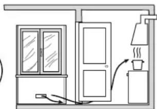
These inlets should be enlarged by 100% - with a minimum of 200 cm ^2 - whenever the surface of the hob is not equipped with a flame failure safety device. When the flow of air is provided in an indirect manner from adjacent rooms (see figure B), provided that these are not communal parts of a building, areas with increased fire hazards or bedrooms, the inlets should be fitted with a ventilation duct leading outside as described above.
A
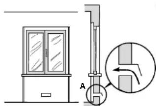
Ventilation opening for
comburent air
B
Adjacent room Room requiring ventilation
natural_image
Simple line drawing of a room with a door, cabinet, and chimney (no text or symbols)Increase in the gap between the door and the flooring
! After prolonged use of the appliance, it is advisable to open a window or increase the speed of any fans used.
Disposing of combustion fumes
The disposal of combustion fumes should be guaranteed using a hood connected to a safe and efficient natural suction chimney, or using an electric fan that begins to operate automatically every time the appliance is switched on (see figure).
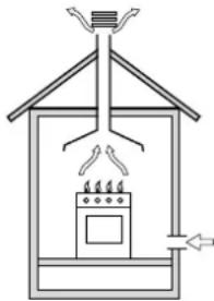
natural_image
Diagram of a house interior with a stove, air conditioner unit, and roof structure (no text or labels)Fumes channelled straight outside
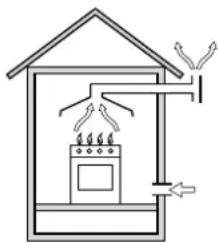
natural_image
Simple line drawing of a house with a stove, roof, and electrical connections (no text or symbols)Fumes channelled through a chimney or a branched flue system (reserved for cooking appliances)
! The liquefied petroleum gases are heavier than air and collect by the floor, therefore all rooms containing LPG cylinders must have openings leading outside so that any leaked gas can escape easily.
LPG cylinders, therefore, whether partially or completely full, must not be installed or stored in rooms or storage areas that are below ground level (cellars, etc.). Only the cylinder being used should be stored in the room; this should also be kept well away from sources of heat (ovens, chimneys, stoves) that may cause the temperature of the cylinder to rise above 50^ C.
Positioning and levelling
! It is possible to install the appliance alongside cupboards whose height does not exceed that of the hob surface.
! Make sure that the wall in contact with the back of the appliance is made from a non-flammable, heat-resistant material (T 90°C).
To install the appliance correctly:
- Place it in the kitchen, dining room or the bed-sit (not in the bathroom).
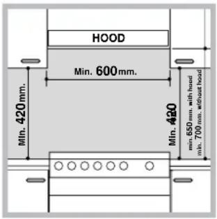
- If the top of the hob is higher than the cupboards, the appliance must be installed at least 200 mm away from them.
- If the cooker is installed underneath a wall cabinet, there must be a minimum distance of 420 mm between this cabinet and the top of the hob.
- If the cooker is installed underneath a wall cabinet, there must be a minimum distance of 420mm between this cabinet and the top of the hob.
This distance should be increased to 700 mm if the wall cabinets are flammable (see figure).
- Do not position blinds behind the cooker or less than 200 mm away from its sides.
- Any hoods must be installed according to the instructions listed in the relevant operating manual.
Levelling
natural_image
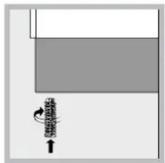
Pure diagram of a mechanical component with no text, numbers, or symbolsIf it is necessary to level the appliance, screw the adjustable feet into the places provided on each corner of the base of the cooker (see figure).
natural_image
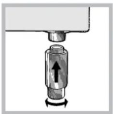
Mechanical component diagram showing a cylindrical assembly with an arrow indicating rotation (no text or symbols)The legs* fit into the slots on the underside of the base of the cooker.
Electrical connection
Install a standardised plug corresponding to the load indicated on the appliance data plate (see Technical data table).
The appliance must be directly connected to the mains using an omnipolar circuit-breaker with a minimum contact opening of 3 mm installed between the appliance and the mains. The circuit-breaker must be suitable for the charge indicated and must comply with NFC 15-100 regulations (the earthing wire must not be interrupted by the circuit-breaker). The supply cable must be positioned so that it does not come into contact with temperatures higher than 50^ C at any point.
Before connecting the appliance to the power supply, make sure that:
- The appliance is earthed and the plug is compliant with the law.
-
The socket can withstand the maximum power of the appliance, which is indicated by the data plate.
-
The voltage is in the range between the values indicated on the data plate.
- The socket is compatible with the plug of the appliance. If the socket is incompatible with the plug, ask an authorised technician to replace it. Do not use extension cords or multiple sockets.
! Once the appliance has been installed, the power supply cable and the electrical socket must be easily accessible.
! The cable must not be bent or compressed.
! The cable must be checked regularly and replaced by authorised technicians only.
! The manufacturer declines any liability should these safety measures not be observed.
Gas connection
Connection to the gas network or to the gas cylinder may be carried out using a flexible rubber or steel hose, in accordance with current national legislation and after making sure that the appliance is suited to the type of gas with which it will be supplied (see the rating sticker on the cover: if this is not the case see below). When using liquid gas from a cylinder, install a pressure regulator which complies with current national regulations. To make connection easier, the gas supply may be turned sideways*: reverse the position of the hose holder with that of the cap and replace the gasket that is supplied with the appliance.
! Check that the pressure of the gas supply is consistent with the values indicated in the Table of burner and nozzle specifications (see below). This will ensure the safe operation and durability of your appliance while maintaining efficient energy consumption.
Gas connection using a flexible rubber hose
Make sure that the hose complies with current national legislation. The internal diameter of the hose must measure: 8 mm for liquid gas supply; 13 mm for methane gas supply.
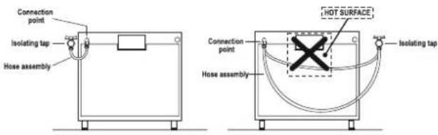
Once the connection has been performed, make sure that the hose:
- Does not come into contact with any parts that reach temperatures of over 50°C.
- Is not subject to any pulling or twisting forces and that it is not kinked or bent.
-
Does not come into contact with blades, sharp corners or moving parts and that it is not compressed.
-
Is easy to inspect along its whole length so that its condition may be checked.
• Is shorter than 1500 mm. - Fits firmly into place at both ends, where it will be fixed using clamps that comply with current regulations.
! If one or more of these conditions is not fulfilled or if the cooker must be installed according to the conditions listed for class 2 - subclass 1 appliances (installed between two cupboards), the flexible steel hose must be used instead (see below).
Connecting a flexible jointless stainless steel pipe to a threaded attachment
Make sure that the hose and gaskets comply with current national legislation.
To begin using the hose, remove the hose holder on the appliance (the gas supply inlet on the appliance is a cylindrical threaded 1/2 gas male attachment).
! Perform the connection in such a way that the hose length does not exceed a maximum of 2 metres, making sure that the hose is not compressed and does not come into contact with moving parts.
Checking the tightness of the connection
When the installation process is complete, check the hose fittings for leaks using a soapy solution. Never use a flame.
Adapting to different types of gas
It is possible to adapt the appliance to a type of gas other than the default type (this is indicated on the rating label on the cover).
Adapting the hob
Replacing the nozzles for the hob burners:
- Remove the hob grids and slide the burners off their seats.
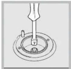
natural_image
Technical line drawing of a mechanical assembly with a tool inserted into a circular component (no text or symbols)- Unscrew the nozzles using a 7 mm socket spanner (see figure), and replace them with nozzles suited to the new type of gas (see Burner and nozzle specifications table).
- Replace all the components by following the above
instructions in reverse.
Adjusting the hob burners' minimum setting:
- Turn the tap to the minimum position.
- Remove the knob and adjust the regulatory screw, which is positioned inside or next to the tap pin, until the flame is small but steady.
! If the appliance is connected to a liquid gas supply, the regulatory screw must be fastened as tightly as possible. - While the burner is alight, quickly change the position of the knob from minimum to maximum and vice versa several times, checking that the flame is not extinguished.
! The hob burners do not require primary air adjustment.
! After adjusting the appliance so it may be used with a different type of gas, replace the old rating label with a new one that corresponds to the new type of gas (these labels are available from Authorised Technical Assistance Centres).
! Should the gas pressure used be different (or vary slightly) from the recommended pressure, a suitable pressure regulator must be fitted to the inlet hose in accordance with current national regulations relating to "regulators for channelled gas".
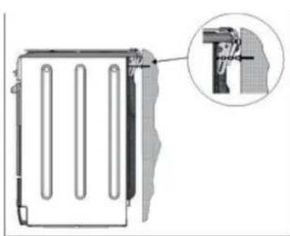
Safety Chain
natural_image
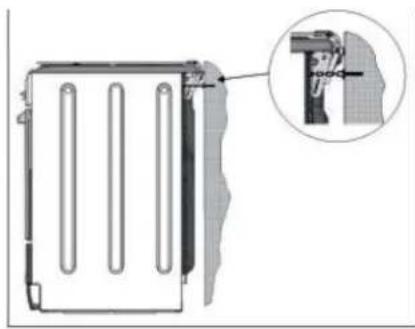
Technical diagram of a mechanical component with an inset close-up showing a detail (no text or symbols)! In order to prevent accidental tipping of the appliance, for example by a child climbing onto the oven door, the supplied safety chain MUST be installed!
The cooker is fitted with a safety chain to be fixed by means of a screw (not supplied with the cooker) to the wall behind the appliance, at the same height as the chain is attached to the appliance.
Choose the screw and the screw anchor according to the type of material of the wall behind the appliance. If the head of the screw has a diameter smaller than 9mm, a washer should be used. Concrete wall requires the screw of at least 8mm of diameter, and 60mm of length.
Ensure that the chain is fixed to the rear wall of the cooker and to the wall, as shown in figure, so that after installation it is tensioned and parallel to the ground level.
KN3G61SA/CZ S KN3G65SA/CZ S
Table of burner and nozzle specifications
* At 15°C and 1013 mbar- dry gas
** Propane P.C.S. = 50,37 MJ/Kg
*** Butane P.C.S. = 49,47 MJ/Kg
Natural P.C.S. = 37,78 MJ/m ^4
| TABLE OF CHARACTERISTSICS | |
| Dimensions (with drawn guide rails) | width 39 cmheight 34 cmdepth 41 cm |
| Volume (with drawn guide rails) | 56 I KN3G61SA/CZ S59 I KN3G65SA/CZ S |
| Maximum absorber power: | See data plate |
| Dimensions of the lower compartment | width 42 cmheight 23 cmdepth 44 cm |
| Burners | may be adapted for use with any type of gas shown on the data plate, which is located inside the flap or, after the oven compartment has been opened, on the left-hand wall inside the oven. |
| ENERGY LABEL | Directive 2002/40/EC on the label of electric ovens.Standard EN 50304Energy consumption for Natural convection – heating mode:Convection; ____Declared energy consumption for Forced convection Class – heating mode:Baking |
| This appliance conforms to the following European Economic Community directives: 2006/95/EC dated 12/12/06 (Low Voltage) and subsequent amendments - 2004/108/EC dated 15/12/04 (Electromagnetic Compatibility) and subsequent amendments - 93/68/EEC dated 22/07/93 and subsequent amendments.2002/96/EC2009/142 of 30/11/09 (Gas)1275/2008 (Stand-by/ Off mode) | |
Data plate, is located inside the flap or, after the oven compartment has been opened, on the left-hand wall inside the oven.
Table 1 Liquid Gas Natural Gas
| Burner Diameter (mm) | Thermal Power kW (p.c.s.)* | By-Pass 1/100 (mm) (mm) *** * (mm) | Nozzle 1/100 (mm) | Flow* g/h | Nozzle 1/100 | Flow* l/h | ||
| Nominal | Reduced (m) | |||||||
| Fast (Large)(R) | 100 3.0 | 0 0.7 41 | 87 | 218 | 214 | 28 286 | ||
| Semi Fast (Medium)(S) | 75 | 1.90 | 0.4 | 30 | 70 | 138 | 136 | 104 |
| Auxiliary (Small)(A) | 51 | 1.00 | 0.4 | 30 | 52 | 73 | 71 | 76 |
| Supply Pressures | Nominal (mbar)Minimum (mbar)Maximum (mbar) | 302035 | 302035 | 201725 | ||||
Using the hob
Lighting the burners
For each BURNER knob there is a full ring showing the strength of the flame for the relevant burner.
To light one of the burners on the hob:
- Bring a flame or gas lighter close to the burner.
- Press the BURNER knob and turn it in an anticlockwise direction so that it is pointing to the maximum flame setting ⬆.
- Adjust the intensity of the flame to the desired level by turning the BURNER knob in an anticlockwise direction. This may be the minimum setting ⬆, the maximum setting ⬆ or any position in between the two.
If the appliance is fitted
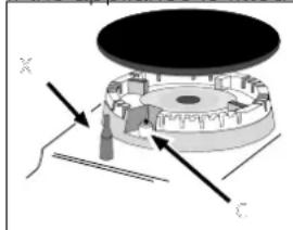
natural_image
Mechanical assembly diagram showing a rotating disk with labeled axes (X, Y, Z) and directional arrows indicating motion or force (no text or symbols beyond axis labels)with an electronic lighting device* (C), press the BURNER knob and turn it in an anticlockwise direction, towards the minimum flame setting, until the burner is lit. The burner may be extinguished when the knob is released. If this occurs,
repeat the operation, holding the knob down for a longer period of time.
f the appliance is equipped with a flame failure safety device (X), press and hold the BURNER knob for approximately 3-7 seconds to keep the flame alight and to activate the device.
! If the flame is accidentally extinguished, switch off the burner and wait for at least 1 minute before attempting to relight it.
To switch the burner off, turn the knob until it reaches the stop position •.
When the selector knob is in any position other than the off position, the 'on' light is illuminated.
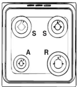
Practical advice on using the burners
For the burners to work in the most efficient way possible and to save on the amount of gas consumed, it is recommended that only pans that have a lid and a flat base are used. They should also be suited to the size of the burner:
To identify the type of burner, please refer to the diagrams contained in the "Burner and nozzle specifications".
| Burner r Cookware diameter (cm) | |
| Fast (R) 24 - 26 | |
| Semi Fast (S) 16 - 20 | |
| Auxiliary (A) 10 - 14 | |
Using the oven
! The first time you use your appliance, heat the empty oven with its door closed at its maximum temperature for at least half an hour. Ensure that the room is well ventilated before switching the oven off and opening the oven door. The appliance may emit a slightly unpleasant odour caused by protective substances used during the manufacturing process burning away.
! Before operating the product, remove all plastic film from the sides of the appliance.
! Never put objects directly on the bottom of the oven; this will avoid the enamel coating being damaged.
-
Select the desired cooking mode by turning the SELECTOR knob.
-
Select the recommended temperature for the cooking mode or the desired temperature by turning the THERMOSTAT knob.
A list detailing cooking modes and suggested cooking temperatures can be found in the relevant table (see Oven cooking advice table).
During cooking it is always possible to:
- Change the cooking mode by turning the SELECTOR knob.
- Change the temperature by turning the THERMOSTAT knob.
- Stop cooking by turning the SELECTOR knob to the "0" position.
! Always place cookware on the rack(s) provided.
THERMOSTAT indicator light
When this is illuminated, the oven is generating heat. It switches off when the inside of the oven reaches the selected temperature. At this point the light illuminates and switches off alternately, indicating that the thermostat is working and is maintaining the temperature at a constant level.
Oven light
This is switched on by turning the SELECTOR knob to any position other than "0". It remains lit as long as the oven is operating. By selecting 🐘 with the knob, the light is switched on without any of the heating elements being activated.
Timer\*
To activate the Timer proceed as follows:
- Turn the TIMER knob in a clockwise direction for almost one complete revolution to set the buzzer.
- Turn the TIMER knob in an anticlockwise direction Ⓧ to set the desired length of time.
Cooking modes

BAKING mode
Temperature: any temperature between 50^ C and Max. The rear heating element and the fan come on, guaranteeing delicate heat distributed uniformly throughout the oven.
This mode is ideal for baking and cooking delicate foods - especially cakes that need to rise - and for the preparation of certain tartlets on 3 shelves at the same time. Here are a few examples: cream puffs, sweet and savoury biscuits, savoury puffs, Swiss rolls and small portions of vegetables au gratin, etc....
CONVECTION mode
Temperature: any temperature between 50^ C and Max. On this setting, the top and bottom heating elements come on. This is the classic, traditional type of oven which has been perfected, with exceptional heat distribution and reduced energy consumption. The convection oven is still unequalled when it comes to cooking dishes made up of several ingredients, e.g. cabbage with ribs, Spanish style cod, Ancona style stockfish, tender veal strips with rice, etc. Excellent results are achieved when preparing veal or beef-based dishes as well (braised meats, stew, goulash, wild game, ham etc.) which need to cook slowly and require basting or the addition of liquid. It nonetheless remains the best system for baking cakes as well as fruit and cooking using covered casserole dishes for oven baking. When cooking in convection mode, only use one dripping pan or cooking rack at a time, otherwise the heat distribution will be uneven. Using the different rack heights available, you can balance the amount of heat between the top and the bottom of the oven. Select from among the various rack heights based on whether the dish needs more or less heat from the top.

FAN ASSISTED mode
Temperature: any temperature between 50^ C and Max. The heating elements, as well as the fan, will come on. Since the heat remains constant and uniform throughout the oven, the air cooks and browns food uniformly over its entire surface. With this mode, you can also cook various dishes at the same time, as long as their respective cooking temperatures are the same. A maximum of 2 racks can be used at the same time, following the instructions in the section entitled: "Cooking On More Than One Rack".
This fan assisted mode is particularly recommended for dishes requiring a gratin finish or for those requiring considerably prolonged cooking times, such as for example: lasagne, pasta bakes, roast chicken and potatoes, etc... Moreover, the excellent heat distribution makes it possible to use lower temperatures when cooking roasts. This results in less loss of juices, meat which is more tender and a decrease in the loss of weight for the roast. The fan assisted mode is especially suited for cooking fish, which can be prepared with the addition of a limited amount of condiments, thus maintaining their flavour and appearance.
Desserts: the fan assisted mode is also perfect for baking leavened cakes.
Moreover, this mode can also be used to thaw quickly white or red meat and bread by setting the temperature to 80 °C . To thaw more delicate foods, set the thermostat to 60 °C or use only the cold air circulation feature by setting the thermostat to 0 °C .

TOP OVENode
Temperature: any temperature between 50^ C and Max. The top heating element comes on.
This mode can be used to brown food at the end of cooking.

GRILL mode
Temperature: any temperature between 50^ C and Max. The top heating element and the turnspit come on.
The extremely high and direct temperature of the grill makes it possible to brown the surface of meats and roasts while locking in the juices to keep them tender. The grill is also highly recommended for dishes that require a high temperature on the surface: such as beef steaks, veal, rib steak, filets, hamburgers etc... Always leave the oven door ajar during cooking, except when using the turnspit.
Some grilling examples are included in the "Practical Cooking Advice" paragraph..

FAN ASSISTED GRILL mode
Temperature: any temperature between 50^ C and 200^ C. The top central heating element and the fan come on. This combination of features increases the effectiveness of the unidirectional thermal radiation of the heating elements through forced circulation of the air throughout the oven. This helps prevent food from burning on the surface, allowing the heat to penetrate right into the food. Excellent results are achieved with kebabs made with meats and vegetables, sausages, ribs, lamb chops, chicken in a spicy sauce, quail, pork chops, etc.
This mode is also ideal for cooking fish steaks, like swordfish, tuna, grouper, stuffed cuttlefish etc.
! The TOP OVEN, GRILL and FAN ASSISTED GRILL cooking modes must be performed with the oven door shut.
! When using the TOP OVEN and GRILL cooking modes, place the rack in position 5 and the dripping pan in position 1 to collect cooking residues (fat and/or grease). When using the FAN ASSISTED GRILL cooking mode, place the rack in position 2 or 3 and the dripping pan in position 1 to collect cooking residues.
! Do not place flammable materials in the lower oven compartment.
! The internal surfaces of the compartment (where present) may become hot.
Practical cooking advice
Cooking on several shelves simultaneously
If it is necessary to use two racks, use the FAN ASSITED mode as this is the only cooking mode suited to this type of cooking. We also recommend that:
- Positions 1 and 5 are not used. This is because excessive direct heat can burn temperature sensitive foods.
- Positions 2 and 4 are used and that food that requires more heat is placed on the rack in position 2.
- When cooking foods that require different cooking times and temperatures, set a temperature that is halfway between the two recommended temperatures (see Oven cooking advice table) and place the more delicate food on the rack in position 4. Remove the food that requires a shorter cooking time first.
* Only available in certain models.
- When cooking pizzas on several racks with the temperature set to 220^ C, the oven is preheated for 15 minutes. Generally speaking, cooking on the rack in position 4 takes longer: we recommend that the pizza cooked on the lowest rack position is removed first, followed by the pizza cooked in position 4 a few minutes later.
- Place the dripping pan on the bottom and the rack on top.
Electronic timer\*
This function displays the time and works as a timer which counts down to zero.
! All functions will be implemented approximately 7 seconds after they have been set.
Resetting the clock
After the appliance has been connected to the power supply, or after a power cut, the clock display will begin to blink, showing the figure: 0:00
- Press button Ⓤ and then buttons - and + to set the exact time. Press and hold the buttons to quicken the count upwards.
Any necessary modifications can be made by repeating the above process.
Timer feature
This function may be accessed by pressing the 🔒 button, after which the display will show the symbol ⚠. Every time the + button is pressed it corresponds to a time increase of 10 seconds, until it reaches 99 minutes and 50 seconds. After this point, each press of the button represents an increase of one minute, up to a maximum of 10 hours.
Pressing the - button reduces the time.
After the time period has been set, the timer will begin to count down. When the timer reaches zero, the buzzer will sound (this may be stopped by pressing any button).
The time may be displayed by pressing the ⏻ button, and the ⏱ symbol indicates that the timer function has been set. After approximately 7 seconds, the display will automatically revert to the timer.
Cancelling a time that has already been set
Press the - button until the display shows 0:00.
Adjusting the buzzer volume
After selecting and confirming the clock settings, use the - button to adjust the volume of the alarm buzzer.
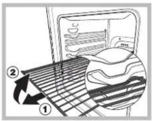
part, and pull (2).
WARNING! The oven is provided with a stop system to extract the racks and prevent them from coming out of the oven.(1) As shown in the drawing, to extract them completely, simply lift the racks, holding them on the front
| Selector knob setting | Food to be cooked Weight (in kg) | Cooking rack position from bottom | Preheating time (minutes) | Thermostat knob setting | Cooking time (minutes) | |
| Baking | Tarts | 0.5 | 3 | 15 | 180 | 20-30 |
| Fruit cakes | 1 | 2/3 | 15 | 180 | 40-45 | |
| Plum cake | 0.7 | 3 | 15 | 180 | 40-50 | |
| Sponge cake | 0.5 | 3 | 15 | 160 | 25-30 | |
| Stuffed pancakes (on 2 racks) | 1.2 | 2-4 | 15 | 200 | 30-35 | |
| Small cakes (on 2 racks) | 0.6 | 2-4 | 15 | 190 | 20-25 | |
| Cheese puffs (on 2 racks) | 0.4 | 2-4 | 15 | 210 | 15-20 | |
| Cream puffs (on 3 racks) | 0.7 | 1-3-5 | 15 | 180 | 20-25 | |
| Biscuits (on 3 racks) | 0.7 | 1-3-5 | 15 | 180 | 20-25 | |
| Meringues (on 3 racks) | 0.5 | 1-3-5 | 15 | 90 | 180 | |
| Convection | Duck | 1 | 3 | 15 | 200 | 65-75 |
| Roast veal or beef | 1 | 3 | 15 | 200 | 70-75 | |
| Pork roast | 1 | 3 | 15 | 200 | 70-80 | |
| Biscuits (short pastry) | - | 3 | 15 | 180 | 15-20 | |
| Tarts | 1 | 3 | 15 | 180 | 30-35 | |
| Fan assisted | Pizza (on 2 racks) | 1 | 2-4 | 15 | 220 | 15-20 |
| Lasagne | 1 | 3 | 10 | 200 | 30-35 | |
| Lamb | 1 | 2 | 10 | 180 | 50-60 | |
| Roast chicken + potatoes Mackerel | 1 | 2-4 | 10 | 180 | 60-75 | |
| Plum-cake | 1 | 2 | 10 | 180 | 30-35 | |
| Cream puffs (on 2 racks) | 0.5 | 2-4 | 10 | 170 | 40-50 | |
| Biscuits (on 2 racks) | 0.5 | 2-4 | 10 | 190 | 20-25 | |
| Sponge cake (on 1 rack) | 0.5 | 2 | 10 | 180 | 10-15 | |
| Sponge cake (on 2 racks) | 1.0 | 2-4 | 10 | 170 | 15-20 | |
| Savoury pies | 1.5 | 3 | 15 | 200 | 25-30 | |
| Top Oven | Browning food to perfect cooking | -3/4 | 15 220 - | |||
| Grill | Soles and cuttlefish | 1 | 4 | 5 | Max | 8-10 |
| Squid and prawn kebabs | 1 | 4 | 5 | Max | 6-8 | |
| Cod filet | 1 | 4 | 5 | Max | 10 | |
| Grilled vegetables | 1 | 3/4 | 5 | Max | 10-15 | |
| Veal steak | 1 | 4 | 5 | Max | 15-20 | |
| Cutlets | 1 | 4 | 5 | Max | 15-20 | |
| Hamburgers | 1 | 4 | 5 | Max | 7-10 | |
| Mackerels | 1 | 4 | 5 | Max | 15-20 | |
| Toasted sandwiches | n.° 4 | 4 | 5 | Max | 2-3 | |
| Fan assisted grill | Grilled chicken | 1.5 | 3 | 5 | 200 | 55-60 |
| Cuttlefish | 1.5 | 3 | 5 | 200 | 30-35 | |
! cooking times are approximate and may vary according to personal taste. When cooking using the grill or fan assisted grill, the dripping pan must always be placed on the 1st oven rack from the bottom.
! This appliance has been designed and manufactured in compliance with international safety standards. The following warnings are provided for safety reasons and must be read carefully.
General safety
- The appliance was designed for domestic use inside the home and is not intended for commercial or industrial use.
- The appliance must not be installed outdoors, even in covered areas. It is extremely dangerous to leave the appliance exposed to rain and storms.
- Do not touch the appliance with bare feet or with wet or damp hands and feet.
- The appliance must be used by adults only for the preparation of food, in accordance with the instructions provided in this booklet.
- The instruction booklet accompanies a class 1 (insulated) or class 2 - subclass 1 (recessed between 2 cupboards) appliance.
- Keep children away from the oven.
- Make sure that the power supply cables of other electrical appliances do not come into contact with the hot parts of the oven.
- The openings used for the ventilation and dispersion of heat must never be covered.
- Always use oven gloves when placing cookware in the oven or when removing it.
- Do not use flammable liquids (alcohol, petrol, etc...) near the appliance while it is in use.
- Do not place flammable material in the lower storage compartment or in the oven itself. If the appliance is switched on accidentally, it could catch fire.
- Always make sure the knobs are in the “●” position when the appliance is not in use.
- When unplugging the appliance, always pull the plug from the mains socket; do not pull on the cable.
- Never perform any cleaning or maintenance work without having disconnected the appliance from the electricity mains.
- If the appliance breaks down, under no circumstances should you attempt to repair the appliance yourself. Repairs carried out by inexperienced persons may cause injury or further malfunctioning of the appliance. Contact Assistance.
- Do not rest heavy objects on the open oven door.
- The appliance should not be operated by people (including children) with reduced physical, sensory or mental capacities, by inexperienced individuals or by anyone who is not familiar with the product. These individuals should, at the very least, be supervised by someone who assumes responsibility for their safety or receive preliminary instructions relating to the operation of the appliance.
- If the cooker is placed on a pedestal, take the necessary precautions to prevent the cooker from sliding off the pedestal itself.
WARNING! The glass lid can break in if it is heated up. Turn off all the burners and the electric plates before closing the lid.
Disposal
- When disposing of packaging material: observe local legislation so that the packaging may be reused.
- The European Directive 2002/96/EC relating to Waste Electrical and Electronic Equipment (WEEE) states that household appliances should not be disposed of using the normal solid urban waste cycle. Exhausted appliances should be collected separately in order to optimise the cost of re-using and recycling the materials inside the machine, while preventing potential damage to the atmosphere and to public health. The crossed-out dustbin is marked on all products to remind the owner of their obligations regarding separated waste collection. For more information relating to the correct disposal of household appliances, owners should contact their local authorities or appliance dealer.
Respecting and conserving the environment
- You can help to reduce the peak load of the electricity supply network companies by using the oven in the hours between late afternoon and the early hours of the morning.
- Always keep the oven door closed when using the GRILL and FAN-ASSISTED GRILL mode cooking. This will achieve better results while saving energy (approximately 10%).
- Check the door seals regularly and wipe them clean to ensure they are free of debris so that they adhere properly to the door, thus avoiding heat dispersion.
Switching the appliance off
Disconnect your appliance from the electricity supply before carrying out any work on it.
Cleaning the appliance
! Never use steam cleaners or pressure cleaners on the appliance.
- The stainless steel or enamel-coated external parts and the rubber seals may be cleaned using a sponge that has been soaked in lukewarm water and neutral soap. Use specialised products for the removal of stubborn stains. After cleaning, rinse well and dry thoroughly. Do not use abrasive powders or corrosive substances.
- The hob grids, burner caps, flame spreader rings and burners may be removed to make cleaning easier; wash them in hot water and non-abrasive detergent, making sure all burnt-on residue is removed before drying them thoroughly.
- For hobs with electronic ignition, the terminal part of the electronic lighting devices should be cleaned frequently and the gas outlet holes should be checked for blockages.
- The inside of the oven should ideally be cleaned after each use, while it is still lukewarm. Use hot water and detergent, then rinse well and dry with a soft cloth. Do not use abrasive products.
- Clean the glass part of the oven door using a sponge and a non-abrasive cleaning product, then dry thoroughly with a soft cloth. Do not use rough abrasive material or sharp metal scrapers as these could scratch the surface and cause the glass to crack.
- The accessories can be washed like everyday crockery, and are even dishwasher safe.
The cover*
natural_image
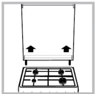
Simple line drawing of a kitchen appliance with a pan and side table (no text or symbols)If the cooker is fitted with a glass cover, this cover should be cleaned using lukewarm water. Do not use abrasive products. It is possible to remove the cover in order to make cleaning the area behind the hob easier. Open the
cover fully and pull it upwards (see figure).
! Do not close the cover when the burners are alight or when they are still hot.
! Remove any liquid from the lid before opening it.
Inspecting the oven seals
Check the door seals around the oven regularly. If the seals are damaged, please contact your nearest Authorised After-sales Service Centre. We recommend that the oven is not used until the seals have been replaced.
Replacing the oven light bulb
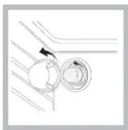
-
After disconnecting the oven from the electricity mains, remove the glass lid covering the lamp socket (see figure).
-
Remove the light bulb and replace it with a similar one: voltage 230 V, wattage 25 W, cap E 14.
-
Replace the lid and reconnect
the oven to the electricity supply.
! Do not use the oven lamp as/for ambient lighting.
Gas tap maintenance
Over time, the taps may become jammed or difficult to turn. If this occurs, the tap must be replaced.
! This procedure must be performed by a qualified technician who has been authorised by the manufacturer.
Assistance
Please have the following information to hand:
• The appliance model (Mod.).
• The serial number (S/N).
This information can be found on the data plate located on the appliance and/or on the packaging.
* Only available in certain models.
natural_image
Simple line drawing of a house interior with a stove and roof structure (no text or symbols)natural_image
Simple line drawing of a house with steam rising from a stove, showing airflow and electrical connections (no text or symbols)natural_image
Simple diagram showing a gray rectangle with a black arrow pointing to it and a small black spiral symbol below (no text or labels)natural_image
Mechanical component diagram showing a cylindrical shaft with a directional arrow indicating motion (no text or symbols)natural_image
Technical line drawing of a mechanical assembly with a tool inserted into a circular component (no text or symbols)natural_image
Mechanical component diagram showing a central hub with four arms and a pointer indicating a specific part (no text or symbols present)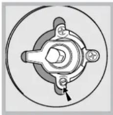
natural_image
Mechanical component diagram showing a central hub with four arms and a bolt, enclosed in a circular housing (no text or symbols)natural_image
Technical diagram of a mechanical component with an inset close-up showing a detail (no text or symbols)KN3G61SA/CZ S KN3G65SA/CZ S
natural_image
Mechanical assembly diagram showing a rotating component with labeled axes X and C (no text or symbols beyond labels)SÜTEMÉNYSÜTÉS program
natural_image
Pure diagram of two circular components with directional arrows, no text or symbols presentnatural_image
Simple line drawing of a gas stove with four fans and two upward arrows (no text or symbols)A fedő eltávolítása
natural_image
Simple line drawing of a house interior with a stove, roof, and piping (no text or symbols)natural_image
Simple line drawing of a house interior with a stove, roof, and ventilation system (no text or symbols)natural_image
Simple diagram showing a gray rectangle with a white top and a black arrow pointing downward (no text or symbols)natural_image
Mechanical component diagram showing a cylindrical assembly with a directional arrow indicating motion (no text or symbols)natural_image
Technical line drawing of a mechanical assembly with a tool inserted into a circular component (no text or symbols)natural_image
Mechanical component diagram showing a central hub with four mounting holes and a pointer indicating a specific part (no text or symbols present)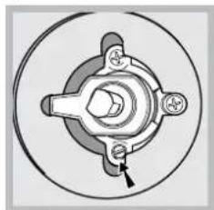
natural_image
Mechanical component diagram showing a central hub with four surrounding parts, no text or symbols present.natural_image
Technical diagram of a mechanical component with an inset close-up showing a detail (no text or symbols)KN3G61SA/CZ S KN3G65SA/CZ S
natural_image
Mechanical assembly diagram showing a rotating disk with labeled axes X and C (no text or symbols beyond labels)Kontrolka CINNOSTI TROUBY
natural_image
Pure diagram of two circular components with a directional arrow, no text or symbols presentnatural_image
Simple line drawing of a table with four small objects and two upward arrows above a vertical structure (no text or symbols)natural_image
Diagram of a steam locomotive cabin with internal components and airflow direction (no text or labels)natural_image
Simple line drawing of an electrical enclosure with insulators and wiring (no text or symbols)Priamo do exteriéru
natural_image
Simple line drawing of a room interior with window, door, and chimney (no text or symbols)Obr. B
Zväcšenie priestoru medzi dverami a podlahou
natural_image
Simple diagram showing a layered structure with a small arrow pointing to a textured bottom section (no text or symbols)natural_image
Mechanical component diagram showing a cylindrical assembly with an arrow indicating rotation (no text or symbols)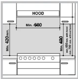
Inštalácia sporáka
natural_image
Diagram of a mechanical device with a central shaft and circular base, no visible text or symbolsnatural_image
Technical diagram of a mechanical component with an inset close-up showing a pin inserted into a housing (no text or symbols present)KN3G61SA/CZ S
KN3G65SA/CZ S
natural_image
Mechanical assembly diagram showing a circular component with labeled axes X and C (no text or symbols beyond labels)natural_image
Simple line drawing of a mechanical assembly with a curved arrow indicating rotation (no text or symbols)natural_image
Simple line drawing of a rectangular frame with a grid base and two small arrows pointing to the top (no text or symbols)natural_image
Diagram of a greenhouse with a stove, roof, and cooling unit (no text or labels)natural_image
Simple line drawing of a house interior with steam rising from the chimney, no text or symbols presentnatural_image
Pure diagram of a mechanical or fluid system with no text, numbers, or symbolsnatural_image
Mechanical component diagram showing a bolt and shaft assembly with an arrow indicating direction (no text or symbols)natural_image
Technical line drawing of a mechanical assembly with a tool inserted into a circular component (no text or symbols)KN3G61SA/CZ S KN3G65SA/CZ S
Sicherheitskette
natural_image
Technical diagram of a mechanical component with an inset close-up showing a detail (no text or symbols)natural_image
Diagram of a mechanical assembly with a central component and surrounding components (no text or labels)natural_image
Simple line drawing of a kitchen appliance with a grater and two upward arrows indicating motion (no text or symbols)
- Operating Instructions COOKER AND OVEN
- Contents
- HU
- Használati útmutató
- FIGYELEM
- Description of the appliance Overall view
- GB
- Description of the appliance Control panel
- A készülék leírása
- Room ventilation
- Disposing of combustion fumes
- Positioning and levelling
- Levelling
- Electrical connection
- ! The manufacturer declines any liability should these safety measures not be observed.
- Gas connection
- Gas connection using a flexible rubber hose
- Connecting a flexible jointless stainless steel pipe to a threaded attachment
- Checking the tightness of the connection
- Adapting to different types of gas
- Adapting the hob
- Table of burner and nozzle specifications
- Using the hob
- Lighting the burners
- Practical advice on using the burners
- Using the oven
- THERMOSTAT indicator light
- Oven light
- Timer\*
- Cooking modes
- BAKING mode
- CONVECTION mode
- FAN ASSISTED mode
- TOP OVENode
- GRILL mode
- FAN ASSISTED GRILL mode
- Practical cooking advice
- Cooking on several shelves simultaneously
- Electronic timer\*
- Resetting the clock
- Timer feature
- Cancelling a time that has already been set
- Adjusting the buzzer volume
- General safety
- Disposal
- Respecting and conserving the environment
- Switching the appliance off
- Cleaning the appliance
- Inspecting the oven seals
- Replacing the oven light bulb
- Gas tap maintenance
- ! This procedure must be performed by a qualified technician who has been authorised by the manufacturer.
- Assistance
- SÜTEMÉNYSÜTÉS program
- A fedő eltávolítása
- Kontrolka CINNOSTI TROUBY
- Inštalácia sporáka
- KN3G61SA/CZ S KN3G65SA/CZ S
Brand : INDESIT
Model : KN3G65SA(W)/CZ S
Category : Cooker