BMK-F 125 - Air extraction system BERBEL - Free user manual and instructions
Find the device manual for free BMK-F 125 BERBEL in PDF.


User questions about BMK-F 125 BERBEL
0 question about this device. Answer the ones you know or ask your own.
Ask a new question about this device
Download the instructions for your Air extraction system in PDF format for free! Find your manual BMK-F 125 - BERBEL and take your electronic device back in hand. On this page are published all the documents necessary for the use of your device. BMK-F 125 by BERBEL.
USER MANUAL BMK-F 125 BERBEL
EN Wall box for exhaust air systems
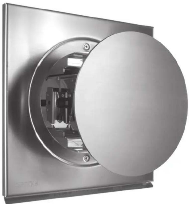
natural_image
Close-up of a metallic circular device with internal components, no visible text or symbolsEN Installation instructions for the models
■ BMK-F 125
■ BMK-F 150
■ BMK-L 125
■ BMK-L 150
■ BMK-Z 150
text_image
C D E barbell

text_image
Technical diagram of a mechanical assembly with numbered components and directional arrows indicating assembly steps.text_image
Technical diagram of a mechanical assembly with numbered components and directional arrows indicating motion or assembly steps.natural_image
Technical diagram of a mechanical component with arrows indicating motion direction (no text or symbols)natural_image
Mechanical assembly diagram showing a square component with rotating arms and screw fasteners (no text or symbols)natural_image
Mechanical assembly diagram showing a motor or actuator component with mounting flanges and housing (no text or symbols visible)natural_image
Technical diagram of a device housing with internal components and rotation arrows, no readable text or symbols present.natural_image
Technical diagram of a cylindrical mechanical component with internal components and wiring (no text or symbols)natural_image
Mechanical assembly diagram showing a screwdriver inserted into a component on a base plate (no text or symbols)natural_image
Two-step diagram showing a cable connector being inserted into a terminal block, with arrows indicating the insertion direction (no text or symbols present)natural_image
Diagram showing a process step with an arrow pointing to a component, no text or symbols presentnatural_image
Diagram of a mechanical device with a cylindrical body and internal components, showing wiring and a black arrow indicating direction (no text or symbols present)natural_image
Diagram showing a process step with an arrow pointing to a component, no text or symbols present7. Élimination....36
text_image
C D E barbell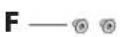

text_image
Technical diagram of a mechanical assembly with numbered components and directional arrows indicating assembly steps.text_image
Technical diagram of a mechanical assembly with numbered components and directional arrows indicating motion or assembly steps.natural_image
Technical diagram of a mechanical component with arrows indicating motion direction (no text or symbols)natural_image
Mechanical assembly diagram showing a square component with rotating arms and fasteners, no text or symbols presentVisser la fixation murale.
natural_image
Mechanical assembly diagram showing a housing with internal components and a black arrow indicating direction (no text or symbols)natural_image
Technical diagram of a device showing internal components and a circular component labeled 'berbal', with no readable text or symbols beyond the label.natural_image
Diagram of a cylindrical device with internal components and wiring, no text or symbols presentnatural_image
Mechanical assembly diagram showing a screwdriver inserted into a component on a base plate (no text or symbols)natural_image
Diagram showing two configurations of electrical connectors with arrows indicating connection points (no text or symbols present)natural_image
Diagram showing a mechanical assembly with a shaft and cross-section, no text or symbols presentnatural_image
Diagram of a mechanical device with internal components and cable routing (no text or symbols)natural_image
Diagram showing a process step with an arrow pointing to a component, no text or symbols present- Cause possible.
Solution.
text_image
C D E barbell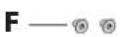

2.4 Dati tecnici
text_image
Technical diagram of a mechanical assembly with numbered components and directional arrows indicating assembly steps.text_image
Technical diagram of a mechanical assembly with numbered components and directional arrows indicating motion or assembly steps.natural_image
Technical diagram of a mechanical component with arrows indicating motion direction (no text or symbols)natural_image
Mechanical assembly diagram showing a square component with rotating arms and fasteners, no text or symbols presentnatural_image
Mechanical assembly diagram showing a motor or actuator component with mounting flanges and housing (no text or symbols visible)natural_image
Technical diagram of a device showing internal components and a circular component labeled 'berbal', with no readable text or symbols beyond the label.natural_image
Diagram of a cylindrical device with internal components and wiring, no text or symbols presentnatural_image
Mechanical assembly diagram showing a screwdriver inserted into a component on a base plate (no text or symbols)natural_image
Two-step diagram showing a cable being inserted into two resistors, one with black arrows indicating the insertion direction (no text or symbols present)natural_image
Diagram showing a mechanical assembly with a shaft and housing, no text or symbols presentnatural_image
Diagram of a mechanical or electrical component with a cylindrical body and internal wiring, showing no text or symbols.natural_image
Diagram showing a process step with an arrow pointing to a component, no text or symbols presenttext_image
C D E barbell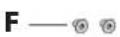

text_image
Technical diagram of a mechanical assembly with numbered parts and directional arrows indicating assembly steps.text_image
Technical diagram of a mechanical assembly with numbered components and directional arrows indicating motion or assembly steps.natural_image
Technical diagram of a mechanical component with arrows indicating motion or assembly (no text or symbols)natural_image
Mechanical assembly diagram showing a square component with rotating arms and screw fasteners (no text or symbols)natural_image
Mechanical assembly diagram showing a motor or actuator component with mounting flanges and housing (no text or symbols visible)natural_image
Technical diagram of a device showing internal components and a circular component labeled 'berbal', with no readable text or symbols beyond the label.natural_image
Technical diagram of a mechanical assembly with a cylindrical component and wires, no visible text or symbolsnatural_image
Mechanical assembly diagram showing a screwdriver inserted into a metal bracket with mounting holes (no text or symbols)natural_image
Two-step diagram showing a cable connector being inserted into a terminal block, with arrows indicating the insertion direction (no text or symbols present)natural_image
Diagram showing a process step with an arrow pointing to a component, no text or symbols presentnatural_image
Diagram of a mechanical or electrical component with a cylindrical body and internal wiring, showing no text or symbols.natural_image
Diagram showing a process step with an arrow pointing to a component, no text or symbols presentInstallation instructions for:
- Wall box BMK-F 125
• Wall box BMK-F 150
• Wall box BMK-L 125
• Wall box BMK-L 150
• Wall box BMK-Z 150
Descriptions are identical for all models.
Differences are noted separately.
Illustrations show:
• Wall box BMK-F 150
• Originalinstructions.
• Part of the product.
• Copyrightprotected.
- Subject to alteration.
- Duplications, re-printing and distribution only with permission.
Safety information
DANGER!
Notes with the word DANGER warn of a hazardous situation that results in serious injuries or death.
⚠ WARNING!
Notes with the word WARNING warn of a hazardous situation that could result in serious injuries or death.
CAUTION!
Notes with the word CAUTION warn of a situation that could result in minor injuries.
ATTENTION!
Notes with the word ATTENTION warn of a situation that could result in damage to property or to the environment.
Symbol clarification - text
Handling requirement
- Listing
→ Reference to another point in this document
Reference to other documents that should be observed
Symbol clarification - illustrations
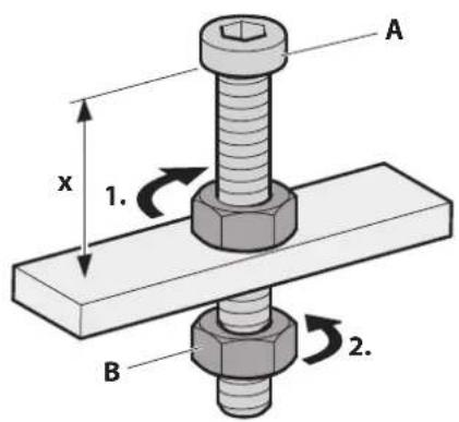
text_image
A x 1. B 2.Highlighting of the parts involved in the action with shading
- Handling steps with numbering
A Part designations with upper case characters
x Dimensions with lower case characters or units in mm
C Movement and direction arrows
Table of contents
1. Safety information ....76
1.1 Proper intended use . . . . . . . . . . . . . . . . . . . . . . . . . . . . . . . . . . . . . . . . . . . . . . . 76
1.2 Authorised target groups....76
1.3 General safety instructions . . . . . . . . . . . . . . . . . . . . . . . . . . . . . . . . . . . . . . . . . . . 76
2. Product information....77
2.1 Product variants....77
2.2 Product overview....77
2.3 Scope of delivery . . . . . . . . . . . . . . . . . . . . . . . . . . . . . . . . . . . . . . . . . . . . . . . . . . . . . . . . . . 78
2.4 Technical data....78
3. Installation....79
3.1 Safety information for installation....79
3.2 Requirements for the installation location .....79
3.3 Requirements for the wall duct: . . . . . . . . . . . . . . . . . . . . . . . . . . . . . . . . . . . . . . . . . . . . . . . 80
3.4 Requirements for the exhaust air duct. . . . . . . . . . . . . . .80
3.5 Installation procedure . . . . . . . . . . . . . . . . . . . . . . . . . . . . . . . . . . . . . . . . . . . . . . . . . . . . . . . . . 81
3.5.1 Preparation for installation 81
3.5.2 Unpack the device 82
3.5.3 Install the protective grating (only for BMK-Z variant) 82
3.5.4 Install the device from outside 83
3.5.5 Connect the device from inside - BMK-F or BMK-Z variant 85
3.5.6 Connect the device from inside - BMK-L variant 86
3.5.7 Check and carry out commissioning ..... 86
4. Cleaning 87
5. Maintenance 88
5.1 Safety information for maintenance .....88
5.2 Maintenance....88
5.3 Fault rectification . . . . . . . . . . . . . . . . . . . . . . . . . . . . . . . . . . . . . . . . . . . . . . . . . . . . . . . . . . . . 88
6. Dismounting 89
7. Disposal....90
7.1 Dispose of packaging . . . . . . . . . . . . . . . . . . . . . . . . . . . . . . . . . . . . . 90
7.2 Dispose of the device . . . . . . . . . . . . . . . . . . . . . . . . . . . . . . . . . . . . . . . . . . 90
8. Contact....91
1. Safety information
1.1 Proper intended use
BMK-F, BMK-L
The device is used to extract cooking vapours to outside. The device completes the exhaust air duct and opens automatically when the cooker hood is operated.
BMK-Z
The device is used to feed fresh air in. When it is open, the air is exchanged between inside and outside.
Only use this device in conjunction with a cooker hood. This device is intended exclusively for use in private households.
It is only permitted to use the device when it is in technically flawless condition and after correct installation. Any other use shall be considered improper use.
The reading and observance of this manual are also included in the proper use of the device.
1.2 Authorised target groups
Electrical work only to be undertaken by qualified electricians in accordance with DIN VDE 0100. Requirements on qualified electricians:
• Knowledge of the basics of electrics.
- Knowledge of country-specific regulations and standards (e.g. in Germany, DIN VDE 0100, part 701).
• Knowledge of the applicable safety regulations.
- Knowledge of the relevant legal requirements for gas installations (e.g. in Germany the technical rules for gas installations TRGI).
• Knowledge of this manual.
Installation and repair only by qualified specialist personnel. Requirements on qualified specialist personnel:
• Knowledge of the regulations on safety at work.
• Knowledge of fastening systems.
• Basic knowledge of ventilation systems.
• Experienced in using electrical and mechanical tools.
• Ability to read technical drawings.
• Knowledge of this manual.
Maintenance by users. Requirements for the user:
• Knowledge of this manual.
There are separate requirements for the following users:
• Children from 8 years and older.
- Persons with restricted physical, sensory or mental capabilities.
• Persons with a lack of experience and knowledge.
These users are only permitted to carry out maintenance. Special requirements:
- Users are supervised.
- Users are instructed with regard to safe use of the device.
- Users understand the hazards involved with the device.
• Children may not play with the device.
1.3 General safety instructions
⚠ WARNING!
Hazard due to disregarding the installation instructions!
This manual contains important information for the safe handling of the device. Separate reference is made to possible hazards.
Read through this manual thoroughly.
Follow the safety instructions in this manual.
Store the manual in an accessible location.
The device must only be used with the following plug-in power supply unit: type "EM1012CHES" from EDACPOWER Electronics Co., Ltd.
The manufacturer accepts no liability for damage occurring in the following circumstances:
• Disregard of this manual.
- Improper use of the device.
- Improper installation and handling of the device.
• Use of the device by unauthorised target groups.
- Bypassing safety equipment on the device.
- Use of replacement parts (e.g. mains cable) that were not produced or approved by the manufacturer.
Further safety instructions can be found in the respective relevant chapter of this manual.
→ "3.1 Safety information for installation" (page 79).
→ "5.1 Safety information for maintenance" (page 88).
2. Product information
The device provides additional functions for the cooker hood.
The wall box opens when the cooker hood is operated. Once the cooker hood is switched off, the wall box closes after a short delay.
When the wall box is closed, the exhaust air duct is sealed and is insulated against sound and heat.
Observe the cooker hood's instructions.
2.1 Product variants
- BMK-F (remote-controlled – extracted air mode) The device receives a signal from the manufacturer's cooker hood.
- BMK-L (air-controlled – extracted air mode) The device receives a signal from a flow detector in sensor tube. The device can be used for cooker hoods from different manufacturers.
- BMK-Z (remote-controlled – inlet air mode) The device receives a signal from the manufacturer's cooker hood. The device can be used in conjunction with the BMK-F or the BMK-L as an alternative to the window contact switch. The "reed switch" retrofit kit is required if the device is connected to the BMK-L variant.
2.2 Product overview
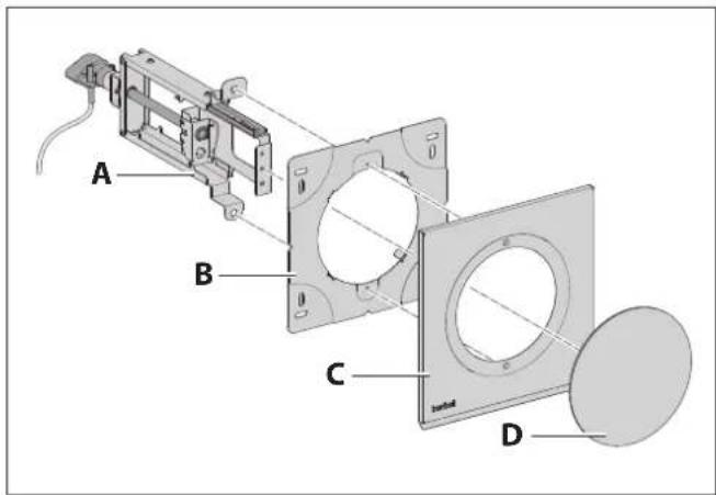
text_image
A B C DA Drive unit
B Wall fastening bracket
C Cover plate
D Wall box plug with outer cover
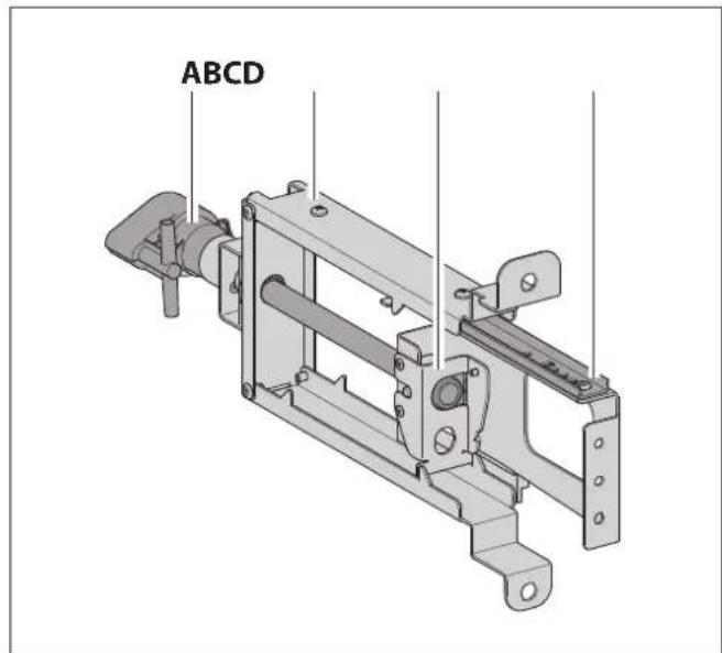
text_image
ABCDA Motor with control electronics
B Frame
C Slide
D Guide rail
2.3 Scope of delivery
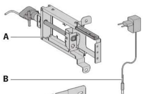
text_image
A B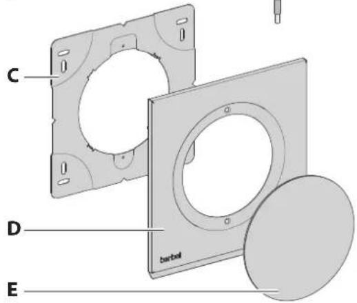
text_image
C D E barbell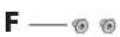

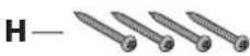

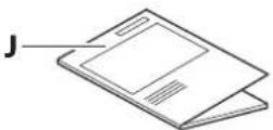
2.4 Technical data
| BMK-... 125 BMK-... 150 | ||
| Connection voltage 230 V / 50 Hz | ||
| Total power | 3 W | 3 W |
| Drive motor voltage | 12 V | 12 V |
| Opening pressure | >40 Pa | >40 Pa |
| Width | 230 mm | 255 mm |
| Depth | 335 mm | 335 mm |
| Height | 239 mm | 264 mm |
| Net weight | 2.0 kg | 2.25 kg |
Information on the model (e.g. serial number, year of construction) is quoted on the front panel.
A Drive unit
• with 3 m control cable (BMK-F, BMK-Z)
• with 70 cm sensor tube (BMK-L)
B 12 volt wall power supply with 1 m connection cable
C Wall fastening bracket
D Cover plate
E Wall box plug with outer cover
F M4 x 5 countersunk screws
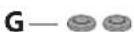
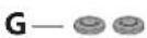
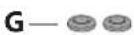
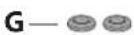
G Grommet for cable bushing
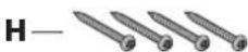
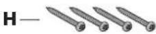
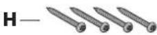
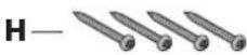
H 4.5 x 50 universal screws
1 Nylon wall plugs, 6 mm
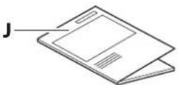
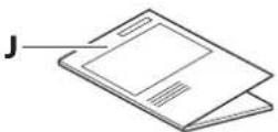
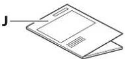
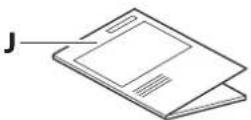
J Installation instructions
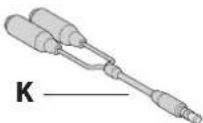
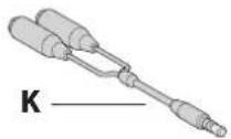
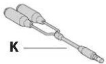
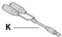
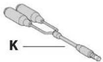
K Y-cable
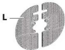
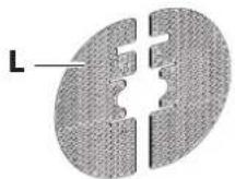
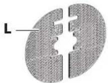
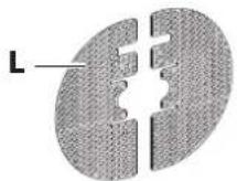
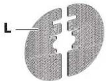
L Protective grating (only BMK-Z)
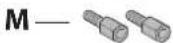
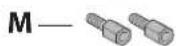
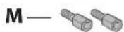
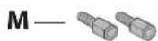
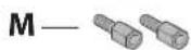
M Thread adapter (only BMK-Z)
3. Installation
3.1 Safety information for installation
⚠ WARNING!
Hazard through disregard of the installation instructions!
This chapter contains important information for the safe installation of the device.
Read through this chapter carefully before installing the device.
Follow the safety instructions.
Carry out the installation as described.
• Installation only by qualified specialist personnel.
→ "1.2 Authorised target groups" (page 76).
- Electrical work only to be undertaken by qualified electricians.
→ "1.2 Authorised target groups" (page 76).
- When working at heights, ensure good stable footing (e.g. stable stepladder).
- Store the film or other parts of the packaging in a location which is inaccessible to children.
- The device must be in an undamaged and fault-free condition prior to installation.
• Cables must not be kinked, crushed or damaged.
- It is not permissible to attach further components (e.g. panels, air ducts) to the device.
- The power supply voltage must match the voltage information quoted on the ratings plate.
→ "2.4 Technical data" (page 78).
- Ensure that the power supply is stable and remains so prior to the installation.
Connect the power supply only when instructed to do so in the installation instructions.
3.2 Requirements for the installation location
⚠ WARNING!
Risk of death due to improper installation!
Disregard of the ambient conditions can lead to hazardous situations, e.g. in the handling of electrical power or gas.
Make sure that the requirements for the installation location are complied with.
- Do not install in potentially explosive atmospheres.
- In extracted air mode and whilst using a heating point which uses air from the room as its oxygen supply (e.g. chimney):
• A safety device is absolutely essential. - The safety device must prevent gases being drawing to the room.
- It is essential to ensure that the negative pressure in the heating point installation room does not exceed 4 Pa.
- An approval for commissioning (e.g. from a chimneysweep) must be available.
• Installation is only permitted on structural building elements capable of bearing the load (solid structure).
• Installation is only permitted on vertical outside walls.
- Suitable fastening materials must be used if the outside wall is insulated.
- Make sure that the building electrical supply is properly earthed.
- The power supply voltage present must match the voltage information quoted on the ratings plate.
- Inside the building, there must be a max. distance of 1 m between the device and a 230 V socket.
- The air flowing out must be able to dissipate unimpeded. Do not impede the air flow, e.g. through the installation of objects on or above the device.
Country-specific, legal provisions must be observed.
3.3 Requirements for the wall duct:
⚠ WARNING!
Risk of death due to improper installation!
A wall break-through influences the structural integrity of the building. There is a danger of collapse. This work must only be carried out by a specialist.
Make sure that the wall duct is established properly.
ATTENTION!
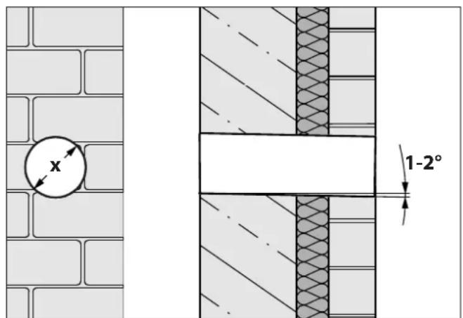
Danger of property damage due to improper installation! If the angle of the wall duct is incorrect, water can flow inside and cause damage.
Make sure that the wall duct is angled 1-2° outwards.
text_image
x 1-2°Diameter (x) of the wall duct:
3.4 Requirements for the exhaust air duct
⚠ WARNING!
Fire hazard and asphyxiation hazard due to improper installation!
When using the exhaust air ducting with other devices or when connecting an active exhaust air channel (e.g. chimney), gases or smoke can be drawn into the room.
Make sure that the requirements for the exhaust air ducting are complied with.
• The exhaust air ducting is used exclusively by this device.
- The exhaust air ducting is made of non-combustible material in accordance with DIN 4102 class B2.
- When routing the exhaust air ducting through the outside wall:
- The cross-section must not be smaller than that of the fan outlet.
- Installation of condensed water collector in the exhaust air ducting in order to prevent water damage inside the device. The condensed water collector must be adequately dimensioned.
- Adequate fresh air supply is assured through the installation of the necessary accessories (e.g. window contact switch).
The cross-section, length, type and course of the exhaust pipe affect the extraction efficiency. Changing the direction of the air too severely leads to a loss of performance and to noise.
To optimise the device performance:
- Keep the exhaust air ducting as short as possible and route it directly to the outside.
- The stipulated cross-section of the exhaust air ducting is complied with.
- Exclusive use of ducts and bends with smooth inner surfaces.
In order to avoid turbulence or backpressure in the transported air - do not use:
- Spiral hoses.
- Flexible tubes.
- Flat deflection pieces.
• Sharp-edged exhaust air channels.
3.5 Installation procedure
Short overview:
- Preparation for installation
- Unpack the device
- Install the protective grating (only for BMK-Z variant)
- Install the device from outside
- Connect the device from inside - BMK-F or BMK-Z variant
- Connect the device from inside - BMK-L variant
- Check and carry out commissioning
3.5.1 Preparation for installation
Familiarise yourself with the installation situation and the associated documents:
• Device and instructions
• Cooker hood instructions
Assemble the tools and materials required:
• Folding rule or measuring tape
- Pencil
- Spirit level
- 6 mm masonry bit
- 10 mm HSS drill bit
- Hammer drill
• Phillips screwdriver
• Construction foam or assembly adhesive
- Silicone compound
Ensure that the cooker hood is installed properly.
c. Ensure that the cooker hood is prepared to be connected to the mains and control cables.
Keep the installation area free of objects that could be in the way or that could be damaged.
Make sure that the hob and other parts that could be touched have cooled down.
Protect the hob and other surfaces in the installation area (e.g. with thick cardboard).
Ensure that the power supply is switched off and remains so. Connect the power supply only when instructed to do so in the installation instructions.
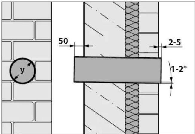
text_image
y 50 2-5 1-2°Ensure that the exhaust air duct is prepared correctly in the wall duct:
- Angled 1 - 2^ outwards.
• Inner diameter (y) of the exhaust air duct:
BMK-... 125 = 123 mm
BMK-... 150 = 148 mm
• 325 mm length to house the device.
• External projection approx. 2-5 mm.
• Internal projection approx. 50 mm.
• Fixed with construction foam or assembly adhesive.
The exhaust air duct requires additional length for the BMK-L variant.
- This must be at least 100 mm if a round pipe is connected.
- This must be at least 250 mm if a transition from a round pipe to a shallow duct is connected
3.5.2 Unpack the device
ATTENTION!
Danger of damage due to improper handling!
The device and its surfaces can be damaged when being unpacked or transported.
Do not cut into the protective cardboard packaging.
Keep objects that could scratch the device far away from it (e.g. tools, belt buckles).
Unpack the device and all accompanying parts carefully.
Set the device down on a firm, clean and protective surface (e.g. thick cardboard).
Check the device and its constituent parts for damage.
Check the delivery is complete.
→ "2.3 Scope of delivery" (page 78).
If parts are missing or damaged:
Please consult your dealer or customer services.
Remove the packaging material and the protective film.
→ "7.1 Dispose of packaging" (page 90).
3.5.3 Install the protective grating (only for BMK-Z variant)
ATTENTION!
Danger of property damage due to improper installation!
The motor or the electronics can become damaged when installing.
Carry out the work steps as described here.
Ensure that the guide rail can move unhindered through the protective grating.
Do not twist the motor housing.
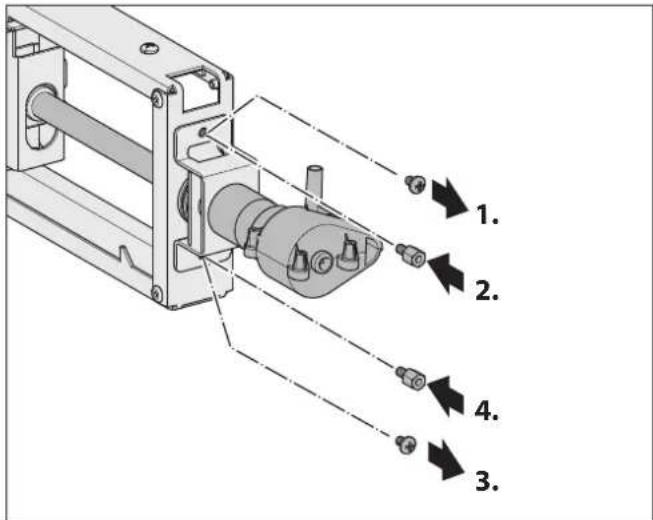
text_image
Technical diagram of a mechanical assembly with numbered components and directional arrows indicating assembly steps.Unscrew the first screw.
Screw the first thread adapter into the free fastening hole.
First unscrew the second screw.
Screw the second thread adapter into the free fastening hole.
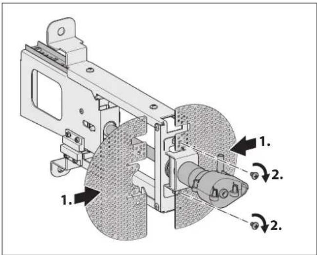
text_image
Technical diagram of a mechanical assembly with numbered components and directional arrows indicating motion or assembly steps.Ensure that the gap for the guide rails is correct.
Slide the parts from the protective grating sideways onto the drive unit until the fastening holes are on top of each other.
- Affix the protective grating by screwing the screws into the thread adapter.
3.5.4 Install the device from outside

natural_image
Technical diagram of a mechanical component with arrows indicating motion or assembly (no text or symbols)Take note of how the wall fastening bracket is aligned:
• Square mounting recess = top
• Round mounting recess = bottom
Align the wall fastening bracket to the centre of the exhaust air duct.
Determine the hanging position.
Determine the locations of the fastening points and mark them.
⚠ WARNING!
Risk of death due to explosions or electric shock!
Drilling through gas, water or electrical lines can lead to hazardous situations.
Ensure that there are no lines in the wall at the fastening points.
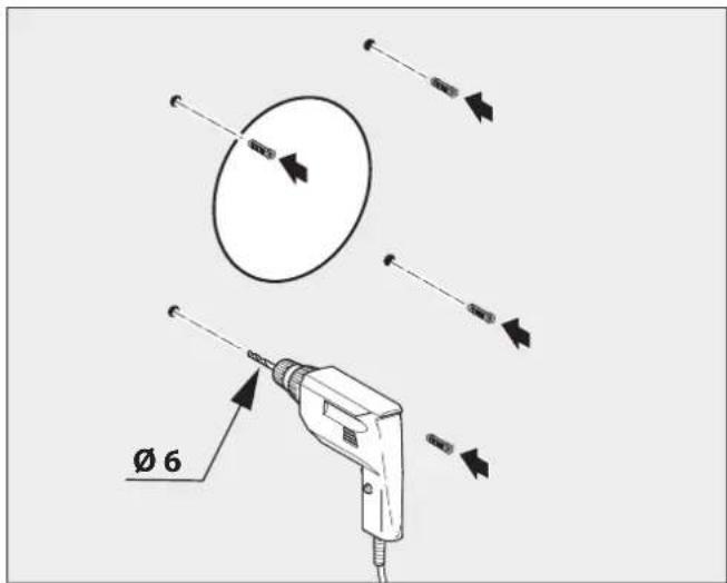
text_image
Ø 6Drill the holes in the wall.
Insert the wall plugs into the holes.
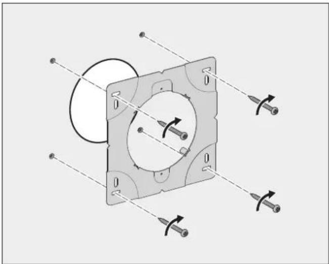
natural_image
Mechanical assembly diagram showing a square component with rotating arms and fasteners, no text or symbols presentScrew the wall fastening bracket on.
Seal the gap between the wall fastening bracket and the exhaust air duct (e.g. using silicone compound).
ATTENTION!
Danger of property damage due to improper installation!
The drive unit can become damaged if it is installed in the exhaust air duct incorrectly.
Ensure that the exhaust air duct is suitable.
→ "3.5.1 Preparation for installation" (page 81).
Insert the drive unit into the exhaust air duct smoothly.
Ensure that the drive unit does not touch the exhaust air duct.
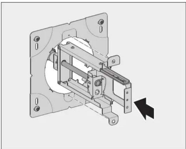
natural_image
Mechanical assembly diagram showing a motor or actuator component with mounting flanges and housing (no text or symbols visible)Take note of how the wall fastening bracket is aligned:
• Square mounting bracket = top
• Round mounting bracket = bottom
Insert the drive unit into the exhaust air duct carefully.
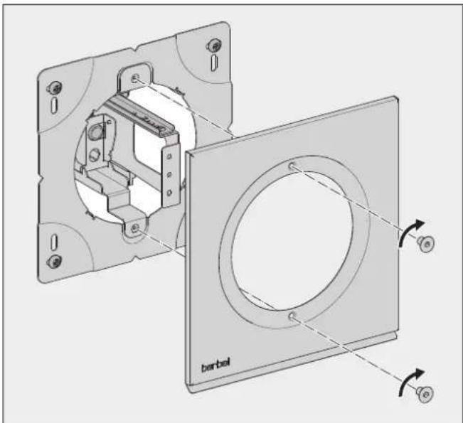
natural_image
Technical diagram of a door frame assembly with labeled components and rotation arrows (no text or symbols beyond label)Align the cover plate downwards with the edge.
Fit the cover plate onto the wall fastening bracket.
Screw the cover plate on.

text_image
berbel 1. 2.Fit the wall box plug with the centring pin on the drive unit.
Push the outer cover with the wall box plug on.
Tighten the outer cover until it is hand-tight and until the markings on the protective film are flush.
Remove the protective film.
The outer cover is aligned correctly if the patterns on the surfaces are aligned.
3.5.5 Connect the device from inside – BMK-F or BMK-Z variant
There are two options for laying the control cable to the cooker hood:
- In the exhaust air duct to the cooker hood and then through an outlet from the exhaust air duct.
- Directly on the wall through an outlet from the exhaust air duct and then parallel to the cooker hood.
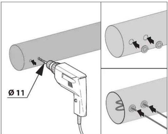
text_image
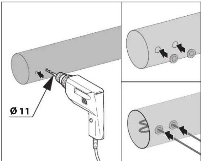
Ø 11Drill an outlet for the connection cable from the wall power supply in the exhaust air duct.
Also drill an outlet for the control cable in the exhaust air duct.
Feed the cable through a grommet and the relevant outlet in the exhaust air duct to the device.
To ensure that dismounting the drive unit is possible:
Lay the connection cable and the control cable so that there is a loop of approx. 250 mm in the exhaust air duct.
Seal the outlets with the grommet.
natural_image
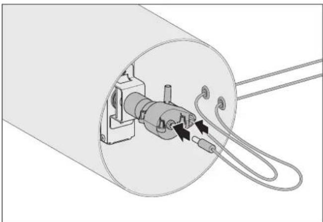
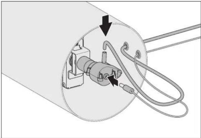
Technical diagram of a cylindrical mechanical component with internal components and wiring (no text or symbols)Connect the connection cable from the wall power supply and the control cable to the device.
For information on connecting the control line, see the cooker hood's instructions.
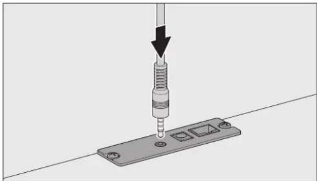
BMK-F
natural_image
Mechanical assembly diagram showing a screwdriver inserted into a metal bracket with mounting holes (no text or symbols)Connect the control cable to the cooker hood.
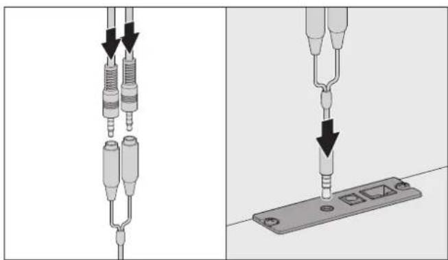
BMK-Z and BMK-F
natural_image
Two-step diagram showing a cable installation with two resistors and a terminal block, no text or symbols present.Connect both control cables to the Y-cable.
Connect the Y-cable to the cooker hood.
natural_image
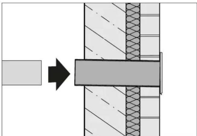
Diagram showing a process step with an arrow pointing to a component, no text or symbols presentConnect the exhaust air duct to the device's inside wall.
Plug the wall power supply's plug into the socket.
The device is ready for operation.
3.5.6 Connect the device from inside - BMK-L variant
The sensor tube must lead back to inside the kitchen. In order to guarantee that the sensor tube works without faults:
- The open end must lead directly into the kitchen's air space.
• The sensor tube must not be kinked.
• The measuring tube must not be closed or blocked.
The sensor tube must be extended if the space conditions require it (maximum length 6 m).
text_image
Ø 11Drill an outlet for the connection cable from the wall power supply in the exhaust air duct.
Also drill an outlet for the sensor tube in the exhaust air duct.
Feed the cable through a grommet and the relevant outlet in the exhaust air duct to the device.
To ensure that dismounting the drive unit is possible:
Lay the connection cable and the sensor tube so that there is a loop of approx. 250 mm in the exhaust air duct.
Seal the outlets with the grommet.
natural_image
Diagram of a mechanical device with internal components and cable routing (no text or symbols)Connect the connection cable from the wall power supply and the sensor tube to the device.

natural_image
Diagram showing a process step with an arrow pointing to a component, no text or symbols presentConnect the exhaust air duct to the device's inside wall.
Plug the wall power supply's plug into the socket.
The device is ready for operation.
3.5.7 Check and carry out commissioning
Check that the mains cable and the electrical connection cable are not kinked, crushed or damaged.
Make sure that the protective film is removed.
Check the correct functioning of the device.
→ "5. Maintenance" (page 88).
The wall box opens when the cooker hood is operated. Once the cooker hood is switched off, the wall box closes after a short delay.
4. Cleaning
ATTENTION!
Danger of damage through improper cleaning!
Sharp-edged objects, abrasive or unsuitable cleaning agents can damage the device.
The following cleaning agents are unsuitable and must not be used:
- Acetone
- Trichloroethylene
- Solutions on a cellulose basis (e.g. cellulose thinner)
• Artificial resin thinner - Abrasive media
• Polishes containing silicone - Polishes containing oil
- Wax
- Water vapour
• On painted surfaces: Microfibre cloth
Keep objects that could scratch the device away from it (e.g. rings).
Use mild household cleaner (e.g. alkali-free, pH-neutral multipurpose cleaner).
Use a soft, damp cloth.
Clean without exercising excessive pressure.
☐ The instructions and information on the cleaning agent should be observed.
- Clean the surfaces with a soft, damp cloth and a mild household cleaner.
Use a suitable care product to treat stainless steel surfaces.
5. Maintenance
5.1 Safety information for maintenance
⚠ WARNING!
Hazard through a disregard of the maintenance instructions!
This chapter contains important information for the safe maintenance of the device.
Read through this chapter carefully before carrying out maintenance work on the device.
Follow the safety instructions.
Carry out the maintenance work as described.
- Repairs only by qualified specialist personnel. “1.2 Authorised target groups” (page 76).
- Electrical work only to be undertaken by qualified electricians.
→ "1.2 Authorised target groups" (page 76).
- Maintenance only by authorised users.
→ "1.2 Authorised target groups" (page 76).
- No maintenance work permitted by children under 8 years old and persons who would not be able to properly assess the hazards associated with handling the device.
5.2 Maintenance
The device does not require maintenance.
5.3 Fault rectification
Possible faults are described below: Description of the fault.
- Possible cause.
Remedy.
The device does not work.
- No power supply. The wall power supply is not plugged into the socket securely.
Ensure that the wall power supply is plugged into the socket securely. - No power supply. The socket is de-energised or the breaker has tripped.
Check to see if the breaker has tripped.
If you use electric circuit breakers, turn the circuit breaker on again.
For other types of breaker or if the socket is de-energised, consult a qualified electrician.
The BMK-F wall box does not open or close, even after a switching time delay of approx. 20 seconds.
- The control contact for the wall box on the cooker hood is not connected correctly or is faulty.
Contact a qualified electrician to check the control contact.
The BMK-L wall box does not open.
- The sensor tube is in a closed air space that only has a slight connection or no connection to the ambient air in the kitchen (e.g. closed suspended cabinet, hood shaft or a suspended, sealed ceiling).
Ensure that the sensor tube ends in the kitchen and has a direct connection to the kitchen's ambient air.
• The sensor tube is blocked or kinked.
Ensure that the sensor tube is not kinked and that the duct is clear.
- The second measuring tube's flow hole is blocked.
Ensure that the flow hole is not blocked.
If a fault persists:
Please consult your dealer or customer services.
6. Dismounting
ATTENTION!
Danger of property damage due to improper dismounting!
The device can become damaged due to incorrect handling when dismounting.
Be careful when loosening and removing components.
Ensure that cables and tubes are not broken.
Do not twist the motor housing.
Disconnect all poles of the power supply from the device.
Unplug the wall power supply's plug from the socket.
If present:
Disconnect the control cable from the cooker hood.
Remove the exhaust air duct on the inside.
Remove the cable and tube connections from the device.
Turn the outer cover in an anticlockwise direction.
Remove the outer cover with the wall box plug.
Unscrew the screws from the cover plate.
Remove the cover plate.
Pull the drive unit out of the exhaust air duct carefully.
Loosen and remove the wall fastening bracket.
7. Disposal
7.1 Dispose of packaging
ATTENTION!
Risk of environmental damage due to improper disposal of the packaging!
Do not put the packaging into the normal household waste.
Take the packaging for environmentally friendly and proper recycling.
The packaging provides protection from transport damage. Only the original packaging guarantees sufficient protection during transportation.
Store the packaging in a location which is inaccessible to children.
The packaging materials have been selected from an environmentally friendly perspective and are made from re-usable materials. The packaging materials can be returned to the raw materials cycle after use. This saves valuable raw materials.
• The outer packaging is made from cardboard.
- The filling material and the insets are made from cardboard or polythene (PE).
- The protective film and bags are made from polythene (PE).
- Dispose of the packaging in an environmentally friendly manner, separated by materials.

7.2 Dispose of the device
ATTENTION!
Risk of environmental damage due to improper disposal of the device!
The device is subject to the European Directive 2012/19/EU and should not be disposed of with household waste.
Do not put the device into the normal household waste at the end of its service life.
Enquire about the disposal options or environmentally friendly and proper recycling opportunities with your municipal or regional authorities.
Correct submission of the device at the time of disposal makes a contribution to the reuse of materials and the protection of resources.
Disposition of the device in accordance with the legal provisions via a professional disposal centre, at your local disposal facility, or by returning it to a distributor subject to take-back obligations.
If primary batteries or rechargeable batteries are used:
Remove the batteries from the device.
Disposition of primary batteries and rechargeable batteries by returning them to the distributor of the respective type of battery, or through submission to a local disposal facility.

If you have any questions or suggestions, please select from the following options:
Mon to Thu 08:00 – 17:30 hrs
and Fri 08:00 – 16:30 hrs
Fax: +49 (0) 5971 8080 9-10
Internet: www.berbel.de
email: info@berbel.de
Contact the manufacturer's customer support department
There are several ways for you to contact our customer service. Please select from the following options:
Tel: +49 (0)5971 80 809-0
Mon to Thu 08:00 – 17:00 hrs
and Fri 08:00 – 15:00 hrs
Fax: +49 (0) 5971 8080 9-10
email: service@berbel.de