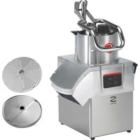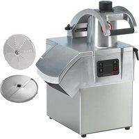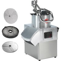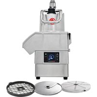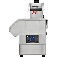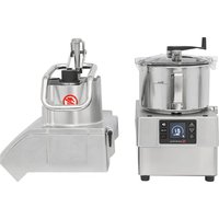
CK-45V - Vegetable cutter Sammic - Free user manual and instructions
Find the device manual for free CK-45V Sammic in PDF.


| Product Type | Professional Vegetable Cutter |
| Brand | Sammic |
| Model | CK-45V |
| Power Supply | 230V / 50-60 Hz / 1~ or 120V / 50-60 Hz / 1~ |
| Power Consumption | 1500 W (2 HP) - 2200 W (3 HP) depending on version |
| Variable Speed | 300 - 3000 RPM (10 speeds in cutter mode, 5 in vegetable cutter mode) |
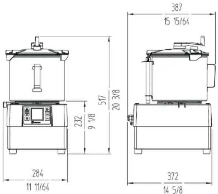
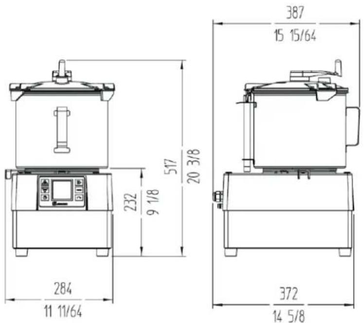
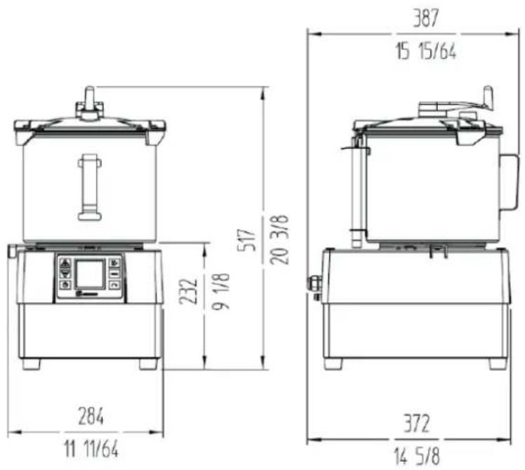
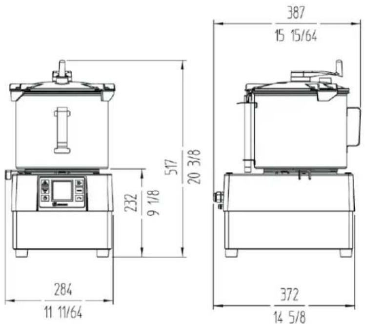
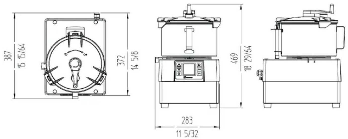
| Dimensions (W x D x H) | 389 x 409 x 667 mm |
| Net Weight | 20 kg |
| Bowl Capacity (cutter) | 5 liters |
| Main Functions | Slicing, french fries, dicing, grating, chopping, sauces, purées, doughs |
| Included Accessories | Discs (A), grids (B), ejector (C), pusher (M), normal bowl (K), cylindrical bowl (L), knives (T), drill key (P), disc protector (R) |
| Operating Modes | Vegetable Cutter and Cutter |
| Electronic Control | Screen with icon display, start/stop keys, pulse, reverse rotation, timer, speed adjustment, programs P1/P2/P3 |
| Safety Features | Head detection, hinged lid, pusher, automatic shut-off after 30 min |
| Cleaning | Disassemble parts in contact with food, clean with soapy water and alcohol disinfection, no dishwasher for CK/CA accessories |
| Maintenance | Check safety features before each use, change the sealing ring, replace cable by approved service center |
| Noise | < 70 dB(A) at 1 m |
| Certifications | Compliant with safety and hygiene standards (120 V: UL-763, ANSI NSF-8) |
| Intended Use | Hospitality, restaurants, shops, caterers (not continuous industrial use) |
Frequently Asked Questions - CK-45V Sammic
User questions about CK-45V Sammic
0 question about this device. Answer the ones you know or ask your own.
Ask a new question about this device
Download the instructions for your Vegetable cutter in PDF format for free! Find your manual CK-45V - Sammic and take your electronic device back in hand. On this page are published all the documents necessary for the use of your device. CK-45V by Sammic.
USER MANUAL CK-45V Sammic
Vegetable preparation machine - cutter
MANUAL DE INSTRUÇÕES
INSTRUKCJA OBSŁUGI
GEBRUIKERSHANDLEIDING
ES
EN
DE
FR
IT
PT
PL
NL
(FIG 1)
text_image
1 2 3 4 5 6 7 8 9 10 88 88:88 RPM 88:88"(FIG 2)
text_image
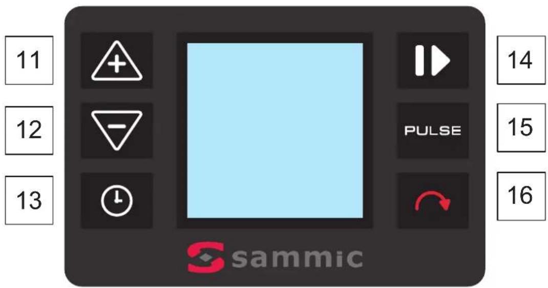
11 12 13 + - - PULSE sammic 14 15 16(FIG 3) CK-35V/CK-38V/CA-3V
text_image
A O M L K N J I B C E D F Y G H(FIG 4) CK-45V/CK-48V/CA-4V (FIG 5) CK-35V/CK-45V/KE-5V/CK-38V/CK-48V/KE-8V
text_image
P Q R A O M L K J I C E D F G H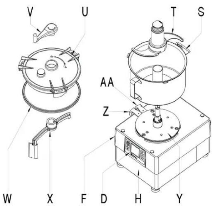
text_image
V U T S W X F D H Y AA ZFIG 1
natural_image
Prohibition sign showing a device with no visible text or symbols, crossed out by red prohibition lines (no text or symbols present)Temperature IGBT: °C
Temperatura interior: °C
natural_image
Technical line drawing of a mechanical device with no visible text or symbolsCK-38V / CK-48V / KE-8V

text_image
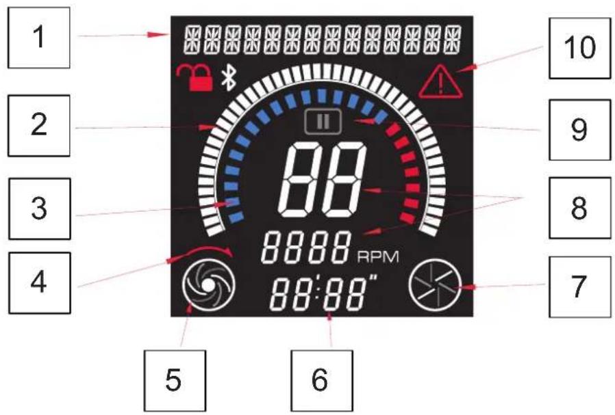
284 11 11/64 232 9 1/8 517 20 3/8 387 15 15/64 372 14 5/81 - Informative text
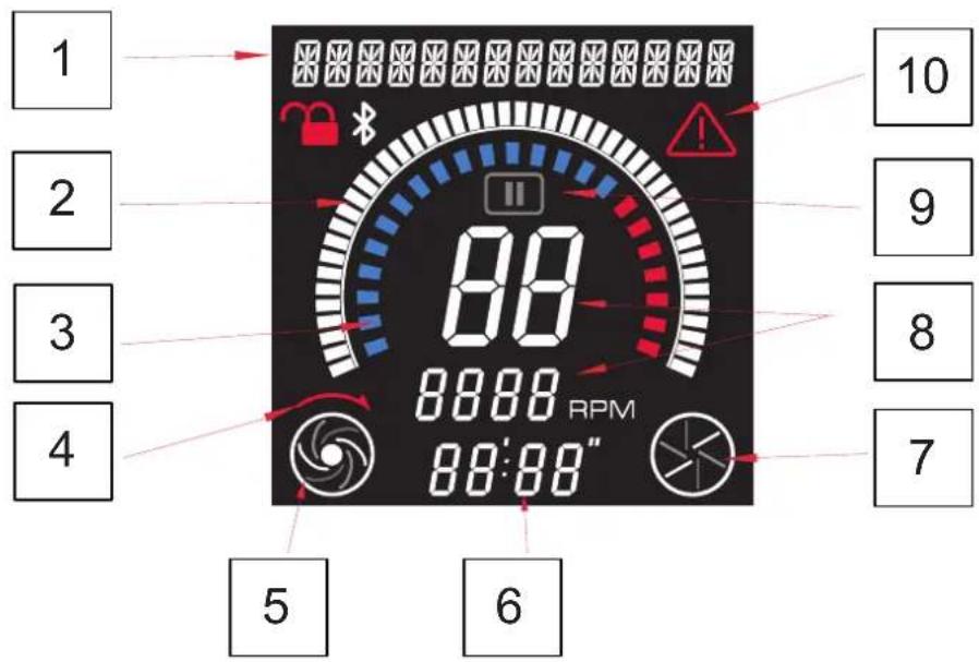
2 - Time display. Cutter mode only.
3 - SensoForce motor display
4 - Reverse rotation activated. Cutter mode only.
5 - Detection of cutter head and shaft rotation. Cutter mode only.
6 - Time display. Cutter mode only.
7 - Detection of cutter head and shaft rotation. Cutter mode only
8 - Speed level and associated RPM
9 - Pause
10 - Alert and error indicator
FIG 2
| Function Initial settings | ||
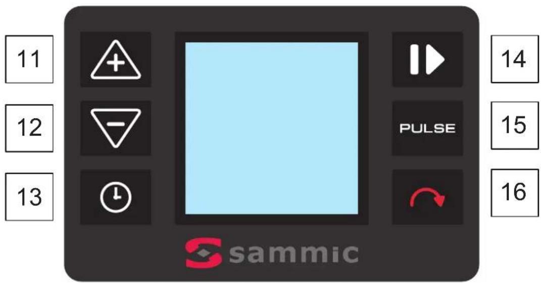
| 13 | Cutter mode. Timer activation Screen display | |
| 11+12 | Real-time parameter display. | |
| 14 | Motor ON / Motor OFF ---- | |
| 15 | Cutter mode. Motor ON while pressed | Select language |
| 16 | Cutter mode. Activate reverse motor rotationCutter mode. Pressing for 3 sec accesses SensoForce function | Counter display |
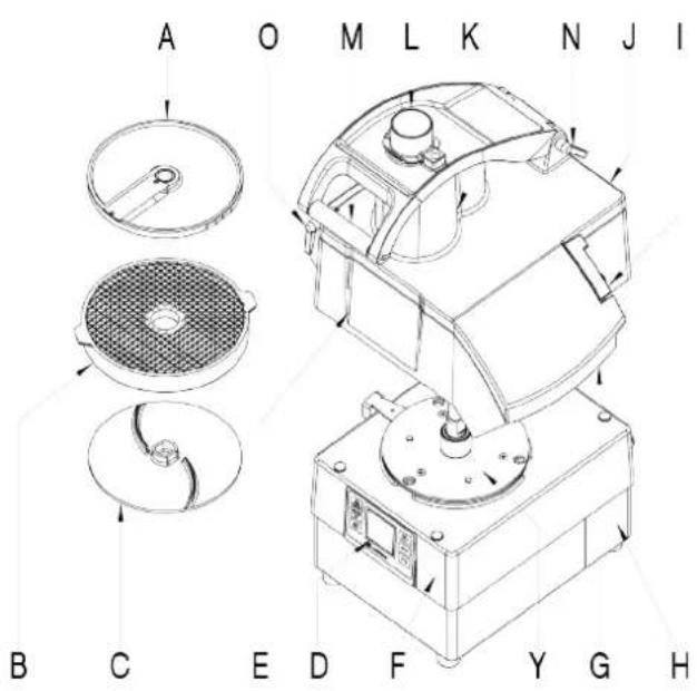
FIG 3 - Technical description
A - Disk
B - Screen
C - Ejector
D - Keyboard
E - Lid
F - Lower lid
G - Evacuation outlet
H - Base
I - Lid closure
J - Articulated removable lid
K - Standard hopper
L - Cylindrical hopper and round mallet
M - Plunger
N - Removable pin
O - Removable pin
Y - Bayonet
Z - Bayonet closed
AA - Bayonet open
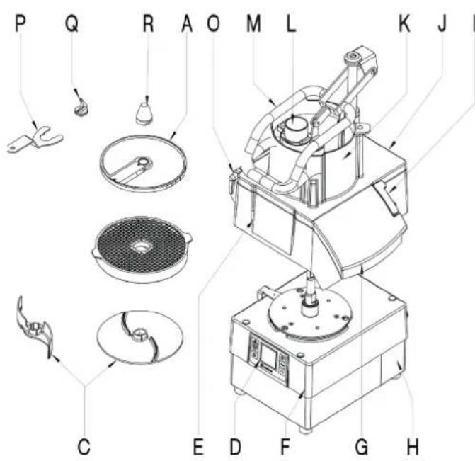
FIG 4 - Technical description
A - Disk
B - Screen
C - Ejector
D - Keyboard
E - Lid
F - Lower lid
G - Evacuation outlet
H - Base
I - Lid closure
J - Articulated removable lid
K - Standard hopper
L - Cylindrical hopper and round mallet
M - Plunger
O - Removable pin
P - Bit key and disk protector
Q - Drill bit
R - Disk protector
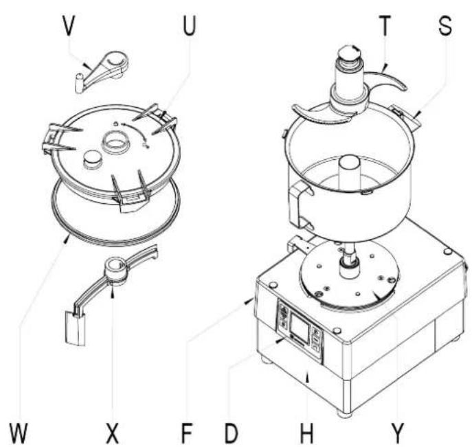
FIG 5 - Technical description
D - Keyboard
F - Lower lid
H - Base
S - Pressure pot
T - Blade
U - Pressure pot lid
V - Mixer crank
W - Pot lid gasket
X - Mixer
Y - Bayonet
Z - Bayonet closed
AA - Bayonet open
Translation of the original instructions
This manual describes the installation, operation and maintenance of the CK-35/38V and CK-45/48V, CA-3V/4V and KE-5V/8V.
Each machine is identified as follows:
- Name and address of the manufacturer: SAMMIC S.L - Basarte 1 Azkoitia. Gipuzkoa (SPAIN).
- Machine model and serial number.
- Approval marks.
- The serial number and all the information regarding the current legislation under which this appliance was manufactured is indicated on the guarantee card and in the declaration of conformity.
NOTE: The 120V models have been approved under the safety standard UL-763 and hygiene and materials standard ANSI NSF-8.
IMPORTANT OBSERVATIONS
- Read and follow these instructions attentively to reduce the risk of accidents (short circuits, injuries or fires, etc.), to get the best performances from the machine and to ensure proper maintenance of the same. Keep the instructions and ensure that all users of the machine read them before use. Also keep the guarantee card and the declaration of conformity.
- Since they are fitted with very sharp blades it is important to handle the disks (A), grids (B) and blade assembly (T) with great care during unpacking, use and cleaning of the machine and its parts. The use of safety gloves is recommended.
- This machine is for supervised use. Never leave the machine running without supervision.
- Clean the food contact area with lukewarm soapy water, rinse and allow to dry before using the machine for the first time.
- The machine must be unplugged from the mains at the end of each operation and before any intervention to change tools or heads, cleaning, review or repair.
- This machine is not designed for use by people (including children) with reduced physical, sensory or mental capabilities or lacking the necessary experience or knowledge unless they have received supervision or instructions from a health and safety expert. Children should be supervised to ensure that they do not play with the appliance.
- The models cited in the manual have been designed for use in hotels, restaurants, catering and retail establishments but should never be used for continuous industrial manufacturing.
- The manufacturer is not responsible when the product is used incorrectly or differently than the use mentioned above. Such as, sanitary use, chemical use, use in explosive atmospheres...
PLACEMENT
It is recommended to place the machine at a comfortable height on a stable surface that does not act as a sounding board. Place the collector under the food outlet. The machine is not secured and can be moved easily.
ELECTRICAL CONNECTION
IMPORTANT! THE EARTH CONNECTION IS OBLIGATORY. DANGER OF ELECTROCUTION.
Check that the machine's electrical specifications match the mains power supply.
The unit is designed for a 230 V 50-60 Hz single-phase or 120 V 50-60 Hz single phase power supply.
Prepare a wall-mounted socket with a general cut-out switch, differential and magneto-thermal 2-pole protection (13 to 20 A) with its associated plug. Place a general switch or the plug in a visibly accessible place to disconnect the machine.
The variable frequency drive is fitted with a filter to derive the disturbances to earth. For this reason, the differential residual current circuit breaker may act unexpectedly. It is advisable to use a suitable residual current device or a super immunised RCD for this machine. The machine is also fitted with an external screw for connection to an equipotential earth connection system (1).
INSTRUCTIONS FOR USE
- Do not allow convenience or familiarity with the product (due to using it repeatedly) to take the place of strict compliance with the safety standards. Stay alert, pay attention to what you are doing and use common sense when operating the unit
- Do not use the machine while you are tired or under the influence of drugs, alcohol or medication. You may suffer personal injury or material damage if you use the tool in an unsafe or incorrect manner.
- NEVER open the lid before the motor has completely stopped.
- NEVER attempt to bypass the blocking or safety systems.
- NEVER put your hand in the food outlet or the feeding hoppers.
- Only insert foodstuffs (never objects) into the hoppers.
- NEVER use external objects to guide the ingredients in the feeding hoppers or outlets.
- The machine must not be overloaded.
- Refrain from exerting excessive pressure with the plungers as this may damage the product and overload the motor.
- 30-minute working periods with 10-minute breaks are recommended.
CLEANING
- Disassemble and clean the machine at the end of each day or each time you change the product or accessory.
- All components in contact with the food must be cleaned immediately after use using hot water and a food-safe detergent. Then rinse with abundant hot water and disinfect using an ethyl alcohol-soaked cloth (90°).
- DO NOT use abrasive detergents (nitric acid, neat bleach, etc.) or non-stainless steel scourers or scrubbers. They may cause the machine to rust.
- The removable parts of the CK and CA should not be washed in a dishwasher. The detergents can damage the surface finish.
- DO NOT clean the outside of the machine with a direct stream of water. Use a damp cloth and any common detergent for cleaning.
MAINTENANCE
- Check that the appliance's safety devices are working correctly before every use. Call the SAMMIC authorised technical service if you detect any anomaly.
- Check the condition of the drive shaft seal weekly to preserve the watertightness of this area. Installing a new seal is recommended every time the drive shaft is loosened for maintenance.
- If the power cable is damaged, a new one must be installed before the machine is used again. Only a SAMMIC authorised technical service may perform this replacement.
The noise level in operation (according to EN ISO 11201:1995) is less than 70 dB(A) with the machine placed at a height of 1.6 m and a distance of 1 m. Background noise: 32dB (A).
FUNCTIONS AND OPERATION OF THE ELECTRONIC CONTROL
ON/OFF (14)
Starts the motor if none of the safety devices impedes it. Pressing a second time stops the motor.
PULSE (15)
Only in Cutter mode. The motor starts and runs as long as this key is held down and stops when it is released.
The language selection menu is accessed during the first 3 seconds when this key is pressed.
REVERSING (16)
Pressing this key in cutter mode for 3 seconds accesses the SENSO FORCE function. SensoForce enables the user to adjust the level at which the acoustic alert indicates that the plunger has reached the desired force. In Cutter mode, pressing this key changes the rotation direction of the motor. This can be done with the motor running or stopped.
The counters that record the work level of the machine are accesses during the first 3 seconds when the key is pressed.
INCREASE (11)
Each time the key is pressed the setting on the display increases. The program version of the power panel appears in the first 3 seconds.
DECREASE (12)
Each time the key is pressed the setting on the display decreases. The program version of the control panel appears in the first 3 seconds.
TIMER (13)
Only in cutter mode. Pressing activates the countdown function. After selecting the time, a second press confirms the selection.
OPERATION
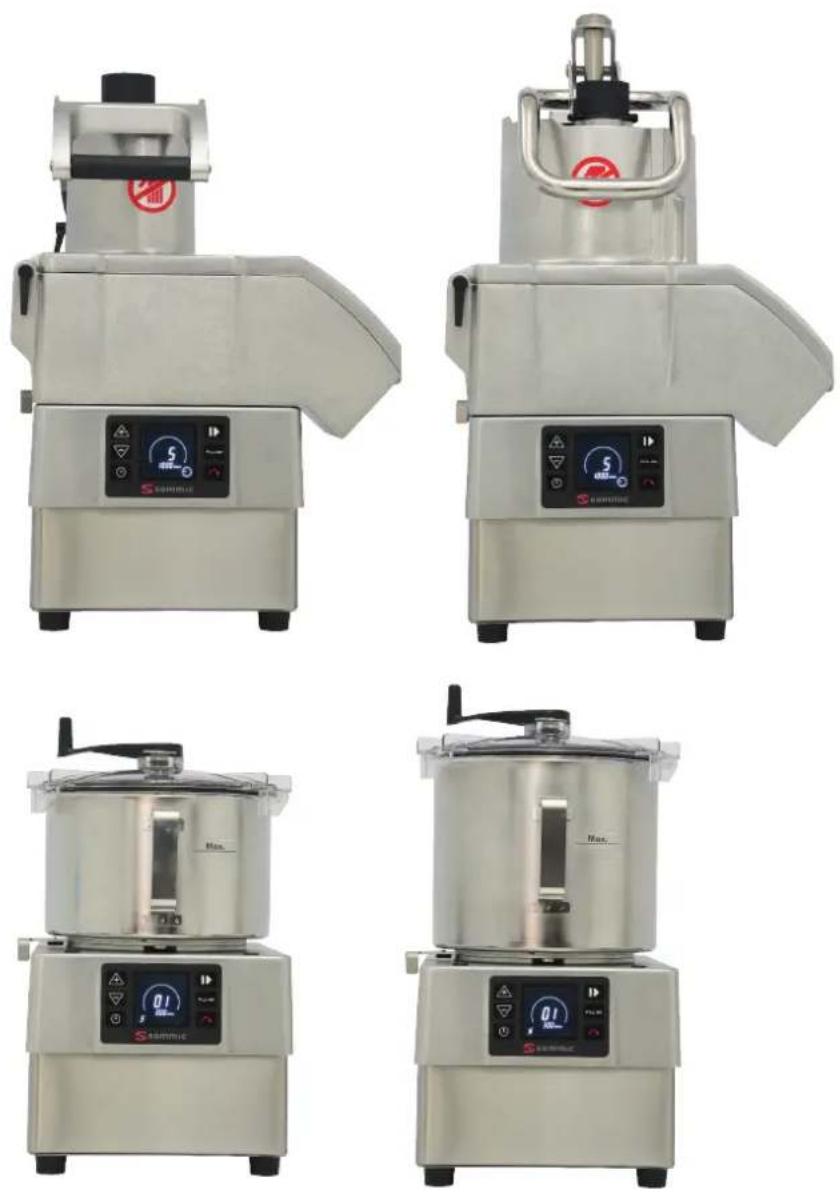
Two lines are displayed in the centre of the screen (1) when the machine is switched on. Icon number 7 (representing a cutting disk) is displayed if the "Vegetable Cutter" accessory is mounted and Icon number 5 (representing a rotor) is displayed if the "Cutter" is mounted. This shows that the control panel has identified each attachment. The speed level and the associated RPM are also displayed.
Ten different speeds (1 to 10) and programmes P1, P2 and P3 can be selected in "Cutter" mode and five different speeds (1 to 5) can be selected in "Vegetable Cutter" mode.
- Time control: Only available in "Cutter" mode. The countdown time and automatic shut-down can also be set.
The appropriate informative text will appear on the screen if "Start" is pressed while any of the safety devices out of position.
START-UP AND GENERAL OPERATION
"Vegetable Cutter" operating mode (CK-35V/38V, CA-3V/8V)
With the machine disconnected from the mains:
- With the bayonet mechanism (Y) open (AA), place the "Vegetable Cutter" accessory on the motor block so that the three lugs are inserted into the holes of the quick-lock mechanism. Close (Z) the bayonet mechanism (Y) to lock the accessory on the motor block.
- The hinged cover (J) on the CK-35V/38V and CK-45V/48V must be fitted as indicated in the drawings and secured with the pin (O).
- The plunger (M) on the CK-35V/38V must be placed as indicated in the drawings and secured with the pin (N).
- If you wish to use the tube head with the CK-35V/38V and CK-45V/48V, it must be placed as indicated in the drawings and secured with the pin (O).
Fitting the disks (A) and grids (B)
- Open the lock (I) and open the hinged lid (J).
- Place the ejector (C) in its housing in the dive shaft.
- The grid (B) is inserted into the cavity in the lower cover (D) when the process so requires.
- Fit a disk (A) on the drive shaft. To do so, insert the disk (A) onto the drive shaft and turn it clockwise until it engages with the shaft.
- On the CK-45V/48V and CA-4V, thread the bit (Q) or the mixer (R) - depending on the product to be cut - onto the drive shaft.
Close (J) and lock (I) the hinged cover.
Start the machine and Icon number 7 (represented by a cutting disk), the speed level and its associated RPM will be displayed on the screen. The speed can be adjusted with the motor running or stopped.
Pressing "Run" (7) with the hinged lid (J) closed and the plunger (M) down will start the motor. Icon 7 will begin to rotate, indicating that the motor is engaged. The "Pause" icon will be displayed if "Start" (7) is pressed with the motor stopped, the hinged lid (J) closed and the plunger (M) up, indicating that the plunger must be lowered. The motor will start up when the plunger (M) is lowered.
The motor will stop if the plunger (M) is raised. The motor re-starts automatically when the plunger (M) is lowered. The "Start" button (7) must be pressed again to start the motor if the plunger (M) is kept in the raised position for more than 30 seconds.
The motor will stop if the hinged lid (J) is opened. The "Start" button (7) must be pressed again to start the machine once the hinged lid (J) has been closed. The machine will stop automatically after 30 minutes if it is left running with the plunger (M) in the lowered position.
An indicative text will appear on the screen if any of the safety devices is out position.
FORCE CONTROL function
- With the motor running, ring 3 on the screen indicates load under which it is working. When the indicator approaches the red zone, it means that the motor is nearing overload. This level varies depending on the features of the product being processed and the force exerted by the plunger.
- An acoustic and visual signal can be configured to warn the user that a certain level of force has been reached. This is useful to ensure that constant force is applied to obtain uniform cutting.
- Pressing on the plunger increases the force until the acoustic signal sounds or the bar can be seen, indicating that the desired level of force has been reached. Maintain this load without increasing the force to obtain uniform cutting throughout the process.
- To set the acoustic signal, hold down the reverse rotation button (16) for 3 seconds to access the menu with which to set the load level at which the acoustic signal will sound. Press the same key 16 again to exit the menu.
Operation with the standard intake hopper (J) and plunger (M). CK-35V/38V and CA-3V.
- The mallet (L) must be housed and locked in its hole. Rotate it anticlockwise to do so.
- Start the machine.
- Raise the plunger (M). The motor will stop.
- Insert the products into the standard hopper (J).
- The motor will start and the cutting process begin once the user begins to press down on the plunger (M). Feed the product by gently lowering the plunger (M). Repeat the process as many times as required.
- Press "Stop" (A) once production has finished.
Operation with the standard intake hopper (K) and plunger (M). CK-45V/48V and CA-4V.
- The mallet (L) must be housed and locked in its hole. Rotate it anticlockwise to do so.
- Start the machine.
- Lift the plunger (M) and turn it anti-clockwise to release the food insertion area of the standard hopper (K). The plunger (M) can be left resting on the plunger support (M). The motor will stop.
- Insert the products into the standard hopper (K).
- The motor starts and the cutting process begins when the plunger (M) is rotated clockwise. Feed the product by gently lowering the plunger (M). Repeat the process as many times as required.
- Press "Stop" (4) to finish.
Operation with cylindrical hopper (L). CK-35V/38V, CK-45V/48V and CA-3V/4V.
This ∅ 55 mm hopper is used to cut long, cylinder-shaped vegetables such as carrots, endives, cucumber, etc.
- Start the machine.
- Release the mallet (L) by rotating it clockwise.
- Insert the products through the hole and push them gently with the "Mallet" (L). Repeat the process as many times as required.
- Press "Stop" (A) once production has finished.
IMPORTANT: Leave the mallet (L) inside the cylindrical hopper when the latter is not in use.
Operation of the CK-35V/38V, CK-45V/48V and CA-3V/4V with tube head.
- The tube head is must be mounted and locked in place.
- Start the machine.
- Insert the products through the upper holes in the tube head. The cutter will stop automatically after working for 30 minutes. To continue, press "Start" again.
- Press "Stop" (4) to finish.
"Cutter" operating mode. (CK-35V/38V, CK-45V/48V and KE-5V/8V):
With the machine disconnected from the mains:
With the bayonet mechanism (Y) open (AA), place the "Cutter" accessory
on the motor block so that the three lugs are inserted into the holes of the quick-lock mechanism. The handle must be placed just above the keypad for the machine to operate. Close (Z) the bayonet mechanism (Y) to lock the accessory on the motor block.
Fit the "Blade assembly" (T) and close the lid (U) by turning it anticlockwise until it is engaged and locked. The lid (B) has a hole through which to feed the product while the machine is operating and a scraper which, when rotated, stirs the contents of the vessel (S) so that they are processed more evenly.
When the machine is switched on the screen will display Icon No. 5 (represented by the rotor) together with the speed level and the associated RPM. The speed can be adjusted with the motor running or stopped.
The motor starts when the "Start" key (A) is pressed and will run until the same key is pressed again or the PULSE B key is held down. It also starts and runs while the PULSE B key is held down. The icon rotates while the motor is running.
The motor rotation direction can be reversed by pressing the C key, either with the motor running or stopped. The associated icon appears on the screen and the speed level is represented by the "-" sign, indicating reverse. With the motor running the icon then rotates in the opposite direction.
Each time the bowl is fitted (with each new process) and the motor starts, a counter appears that counts the duration of the process. This time is reset only when the bowl is removed.
The countdown time can be set by pressing the CLOCK "D" key when fitting the bowl. Accept by pressing the same key again or starting the motor. The countdown will then start. The timer has an associated indicator circle (2) that provides a visual reference of the time remaining until the end of the process. When the time reaches zero the motor stops and a "beep" is emitted.
FORCE CONTROL function
With the motor running, ring 3 on the screen indicates load under which it is working. When the indicator approaches the red zone, it means that the motor is nearing overload. This level varies depending on the features of the product being processed.
Dedicated programmes
With the motor stopped, press the DOWN button (12) until you reach the dedicated programmes P1 (dense texture), P2 (light texture), and P3 (pulses). P1 and P2 are automatic programmes used to obtain a fine and consistent grind. The pre-set time can be changed by pressing the TIME button (13) (when the motor is stopped). P3 is a program of pulses, and it is possible to change the number of pulses produced with the button TIME (13). Press the START button (14) to start it up.
P1 (dense texture) for banana-type products.
P2 (light texture) for tomato-type products.
CLEANING
Cleaning of the "Vegetable Cutter" accessory CK-35V/38V, CK-45V/48V and CA-3V/4V:
- Release the lock (I) and open the hinged cover (J).
- On the CK-45V/48V and CA-4V, holding the disk (A) with your hand without touching the blades, use the key (P) supplied with the machine to remove the bit (Q) or the mixer (R), unscrewing it anticlockwise.
- Remove the disk (A) by turning it clockwise and carefully pulling it upwards. Remove the grid (B) and the ejector (C).
- In the CK-35V/38V and CA-3V the plunger (M) and hinged lid (J) can be dismantled for cleaning. The pins (N and O) must be removed to do so.
WARNING: To be able to remove the products embedded in the grids (B), simply tap them in the cutting direction with an elongated potato or a whole carrot. This prevents damaging the grid (B). Take care with the edge of the grid (B). Never use hard objects to tap the grid (B).
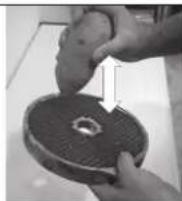
There is also a grid cleaner in the Sammic catalogue for the FMC-8D and FMC-10D grids.
The SH grater disks are designed so that the plate can be separated from the frame for cleaning.
Cleaning the "Cutter" accessory (CK-35V/38V, CK-45V/48V and KE-5V/8V):
- Pour hot water and detergent into the pot and switch the machine on to soften the residue if the fouling is dry and adheres to the pot and the blades.
- To avoid splashes, once the product has been processed, remove the lid (U), place the bayonet safety mechanism (Y) in the open position (AA) and remove the pot (S) with the blade inside (T).
- The mixer (V+X) can be removed from the lid (U). Holding the mixer (X) in place, tighten and turn the mixer crank (V) to do so. The mixer and the mixer crank can be separated once these operations have been performed. To reassemble the mixer, insert the mixer (X) into the lid (U) again and the mixer crank (V) into the mixer (X). Push the mixer (X) and the mixer crank (V) against the lid and turn the mixer crank (X) until it reaches the end stop. Separate the mixer (X) and the mixer crank (V) once these actions have been performed.
Cleaning the CK motor block:
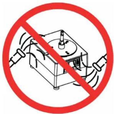
The outside of the machine must NEVER be cleaned with a direct jet of water. Use a damp cloth and any common detergent for cleaning. DO NOT use abrasive detergents (nitric acid, neat bleach, etc.) or non-stainless steel scourers or scrubbers.
text_image
Prohibition sign showing a device crossed out by a red circle, indicating no protection or disapproval."Vegetable Cutter" attachment: Operation of disks (A) and grids (B)
- Disks (A):
- Use disks (A) FC-1+ and FC-2+ to cut potatoes chips or thin 1 and 2-mm slices.
- Disks (A) from FC-3D to FC-25+ to obtain 3 to 25-mm slices of potatoes, carrots, beet, cabbage, cucumber, zucchini, onions, radishes, etc.
- Disks (A) with curved blade for soft products, FCC-2+, FCC-3+ and FCC-5+ to cut tomato, orange, lemon, banana, apple, etc into slices.
- SH-type grater disks (A) 2-7 mm to shred vegetables and grate cheese, bread, nuts, almonds, etc.
Discs FCE-2, FCE-4 and FCE-8 to cut potato "matchsticks" and carrot,
celery, beetroot strips, etc.
- Disks (A) SH-1 and SH-8 to grate bread, cheese, chocolate, etc.
- Disks (A) and grids (B). Possible combinations:
- Disks (A) FC-6D, FC-8D, FC-10D combined with grids (B) FFC-8+ and FFC-10+ to obtain chip-style potatoes.
- Disks (A) FC-3D, FC-6D, FC-8D, FC-10D and FC-
14D combined with grids (B) FMC-8D, FMC-10D and FMC-14D to 3 to 14-mm cubes of potatoes to make tortillas or of vegetables and fruit for fruit salad, Russian salad, etc.
- Disks (A) FC-20+ and FC-25+ combined with grids (B) FMC-20+ and FMC-25+ make 20x20 and 25x25 cubes.
- There is a grid cleaner for the FMC-8D and FMC-10D grids in the Sammic catalogue.
Bit (Q) and Mixer (R). CK-45V/48V and CA-4V.
- Bit (Q): It is only used when working with cabbage and similar vegetables. It is used to cut whole pieces.
- Mixer shaft (R): It must be used with all food except cabbage and similar vegetables.
High and standard ejector (C).
- High ejector: For cutting bulky products such as cabbage, cauliflower, celery and for grated products such as cheese, carrots, etc.
- Standard ejector: For all other cutting jobs.
"Cutter" attachment.
Using the "Cutter" accessory you can:
CHOP: Parsley, garlic, onion, cheese, cooked ham, cooked meat, etc.
SAUCES: Tomato, mayonnaise, tartar, garlic mayonnaise, green sauce, gazpacho, etc.
PUREES: Pulses, vegetables, spreads, etc. PASTA: Prawns, mussels, oysters, meat, sausages, etc.
SOUPS / CREMES: Seafood, garlic, vegetables, legumes, meat, etc.
FLAVOURED BUTTER: Garlic, parsley, fine herbs, anchovies, etc.
Cakes, desserts and pastry:
CHOP: Almonds, hazelnuts, chocolate, raisins, fruit for fruit salad, etc.
PREPARE: Powdered sugar, almond paste, whip cream; creamed chocolate, vanilla, coffee, strawberries and fruit in general, etc.
SHARPENING THE BLADES
WARNING: The discs (A), grids (B) and blade assembly (T) have very sharp edges and must be handled with extreme care.
The disc blades (A) and blade assembly (T) can be removed easily for sharpening. Always use soft stone to avoid damaging the blades' cutting angle.
OPERATING INCIDENTS
The machine fails to start on pressing "Start" (A) when it is ready for operation and the message indicating the action to be performed appears on the display. The associated sensor may not be working.
- Check that all of the components are in position.
- There is a problem with one of the safety devices if the problem persists. Call a SAMMIC authorised technical service.
- The screen fails to turn on: The flat cable that connects the power and control boards is loose or damaged or the electronic control panel is faulty.
- To verify that the keypad is working properly, press the keys with an accessory fitted and verify that the plate emits a beep and the display is
activated. Otherwise, change the keyboard.
- The machine was running and stopped without any key being pressed. If the machine is running it will stop automatically after 30 minutes without human intervention.
In the Vegetable Cutting mode the motor will not start when the plunger (M) is in the lowered position. - Press "Start" (7) again to reset the cutter IF the plunger (M) is left open for more than 30 seconds.
- On the CK-35V/38V/45V/48V and CA-3V/4V the hopper may be too full and the plunger (M) may not activate the microswitch. Reduce the amount of product in the hopper and try again.
- The disk (A) or the blade assembly (C) may be rubbing on another part if the machine is excessively noisy. The main shaft bearings have probably deteriorated.
The unit has its own protection devices that are activated when damage to important components is likely. These protections are represented by a red triangle (1) and a circle (2) lit simultaneously with the explanatory text. Display of these indicators does not mean that the equipment has been damaged but it has detected a status that triggers the programmed protection. Press Start (A) again to reset the protection system. Contact the authorised SAMMIC technical service if the alert persists and does not permit normal operation of the machine. These alerts are recorded in a log that can be consulted.
In addition to the FORCE CONTROL function that enables users to monitor the status of the motor, it is also possible to display some of the machine's parameters while it is running. Pressing and holding the up and down keys simultaneously will display four numbers that indicate the following (from left to right): Motor intensity, motor power, IGBT module temperature and the internal temperature of the machine.
Motor intensity: Tenths of an Ampere
Motor power: W
IGBT temperature: °C
Internal temperature: °C
If any of the alerts persists or if the values indicated in the manual are exceeded, check and asses if the work being done is proportional and try to adjust it in load and rest period to keep the parameters within the proper ranges to avoid tripping the protections. If you consider that the machine is at fault, contact Sammic's authorised technical service.
TROUBLESHOOTING
| ITEM | DESCRIPTION CODE MEANING | ||
| 1 MOTOR OVERHEATING | |||
| The machine stops. The motor heats up from overwork. Let stand a few minutes before using again. Check motor safety thermostat connection on the PCB and on the motor. | |||
| 2 INTERNAL ERROR | |||
| Communication failure between board and screen. It could be the communication wire or some internal component of the PCB. Check the cable or change the PCB. | 224 | Timeout comuni-cation | |
| 225 | No Signal Control | ||
** The temperature of the module (PCB) and the internal temperature of the machine can be displayed. To do this, once the machine is on, press the + and – buttons together for 5 seconds. We find 4 digits at the top of the screen. The first one on the right shows us the internal temperature of the machine, the second the internal temperature of the PCB, the third is the watts and the fourth the consumption in Amps (it must be divided by 10).
| 3 INTERNAL HIGH TEMPERATURE | |||
| The machine stops. The internal temperature of the machine is to hight. If the error gives us after X time working and with a specific job. You must wait until the machine cools down for a few minutes. If it is an error that appears repeatedly due to the type of work they do, a ventilated base (2059604) can be installed in the machine to remove the internal heat from the machine. | |||
| 4 LOW VOLTAGE | |||
| Power has been lost or voltage is too low. If the machine is 230V it would be 184V and if the machine is 120V it would be 92V. Check plug voltage. | 16 | No Voltage OK before Start up | |
| 32 | Low voltage during 2 sec. | ||
| 33 | Instant low voltage (16 readings) | ||
| 5 HIGH VOLTAGE | |||
| Voltage too high. If the machine is 230V it would be 265V and if the machine is 120V it would be 133V. Check plug voltage. | 48 High Voltage | ||
| 6 MOTOR ERROR | |||
| Can be a fault in the motor or in the motor output of the PCB. You should disconnect the motor wire from the PCB and see if it gives the same error, to know if it is a board or motor failure. | 64 | High PWM (Pulse width modulation) during positioning | |
| 70 | No synchronisation | ||
| 7 MOTOR BLOCKED | |||
| Blocked motor, a fault in the motor encoder or in the board controller. Check encoder cable. If the cable is OK, change the board or the motor to rule out one of the two components. | 72 Rotor Blocked | ||
| 8 OVERLOAD | |||
| A punctual motor effort and excessive consumption. Remove power, wait 10 seconds and power the machine again. | 80 | Overload during 1 sec. | |
| 96 | High intensity/consumption peak (16 readings) | ||
| 97 | Intensity/Consumption PWM (Pulse width modulation) period | ||
| 9 MODULE TEMPERATURE | |||
| The machine stops. PCB temperature is too hight. If the error gives us after X time working and with a specific job. You must wait until the machine cools down for a few minutes. If it is an error that appears repeatedly due to the type of work they do, a ventilated base (2059604) can be installed in the machine to remove the internal heat from the machine | 97 | High module temperature 2 sec. | |
| 113 | High instantaneous module temperature (16 readings) | ||
| 114 | High module temperature during Start up with machine OFF | ||
| 120 | High PCB temperature 2 sec. | ||
| 121 | High instantaneous PCB temperature (16 readings) | ||
| 122 | High PCB temperature during Start up with machine OFF | ||
| 10 MOTOR SHORT CIRCUIT | |||
| Can be error in the motor or in the motor output of the board. The motor wire should be disconnected from the PCB and see if it gives the same error. Like that we know if the error is in the PCB or in the motor. | 128 | Short circuit | |
| 129 | Output short | ||
| 131 | Oscillation Stop | ||
INITIAL SETTINGS
The following parameters can be changed on the machine:
1- Language
2- Maintain cutter speed: If enabled, the initial cutter speed will be the one used last time.
3- Maintain FORCE CONTROL: FORCE CONTROL is always active.
4- Maintain programme time: the change of time of a programme is permanent.
5- Programmes (see section "Programmes").
6- Factory settings: reset the machine to return it to its factory settings.
To change these settings:
- Switch on the machine and keep the PULSE button (15) pressed during the first three seconds.
- Use the UP (11) or DOWN (12) buttons to move from one setting to another and choose the one you want to change with the START button (14). If you make a mistake, push the PULSE button (15) once to return to the previous level.
- On the next level, use the UP (11) or DOWN (12) buttons to move from one value to another and confirm with the START button (14). By accepting the change, the machine returns to the previous level. If you make a mistake, push the PULSE button (15) once to return to the previous level.
To exit the settings, push the PULSE button (15)..
CHANGE OF LANGUAGE
- Switch on the machine and keep the PULSE button (15) pressed during the first three seconds.
- Select LANGUAGE with the START button (14).
- Select the language using the UP (11) or DOWN (12) keys and select it with the START button (14).
- Press the PULSE button (15) twice to make the change.
MACHINE COUNTERS
Switch on the machine and keep the START button (14) pressed during the first three seconds: this will access the counters that record the level of machine usage. Pressing UP (11) and DOWN (12) displays the following::
0 HPOW: Hours connected to the power supply.
1 HCUT: Hours with the motor running in Cutter mode.
2 HCOR: Hours with the motor running in Vegetable Cutting mode.
3 NARR: Number of motor starts.
4 NMTERM: Number of thermal manoeuvres of the motor
5 NMCIER: Number of bayonet closing manoeuvres.
6 NMTAPA: Number of manoeuvres of the vegetable cutting lid.
7 NMPCA: Number of manoeuvres of the vegetable cutter plunger and the cutter lid.
Press and hold the Start/Stop button for 3 seconds to reset the counters.
TIMER (13): Turns on all the icons on the screen.
BAJAR (12) The panel version is shown.
SUBIR (11) The program version is shown.
PROGRAMMES
CREATE A NEW PROGRAM
- Unplug the machine and wait 20 seconds before reconnecting.
- Plug in the machine and, within 3 seconds, press and hold the PULSE button (15), which accesses the parameters menu.
- Use the UP keys (11) until you reach the PROGRAMMES parameter and press the START button (14) to access the creation or modification of a program.
- The programmes are called C1, C2, C3... and up to 9 programs can be configured (C9). Use the UP (11) or DOWN (12) keys to locate the program you want to create or modify (C1, C2, C3...).
- Once the program is located, press the START button (14) to start modifying it.
- Once you have accessed the program configuration:
- The screen shows in the upper left the name of the program (C1, C2, C3...) and the phase (1.2,3...) you are configuring.
- To configure a phase press the START button (14).
- Find the function you want to programme (speed, pulse, ...) with the UP (11) and DOWN (12) buttons. Access the selected function with the START button (14). The machine has the following functions:
- SPEED. Select a speed and the time it will be running:
- Use the UP (11) and DOWN (12) buttons to select the working speed (it will be flashing) and press the START button (14) to set it.
- Determine how long you will work at that speed (it will be flashing). Use the UP (11) and DOWN (12) buttons to change the time and the START button (14) to set it.
- The configuration of the function has concluded. Press START (14) to start defining the next phase (1.2,3...).
- PULSE. Select the number of pulses (one second cycles while running) to be performed.
- The number of pulses will appear flashing. Use the UP (11) and DOWN (12) buttons to determine the pulses to be realized and the START button (14) to set it.
- The configuration of the function has concluded. Press START (14) to start defining the next phase (1.2,3...).
- REST. The machine will be stopped for the time you indicate.
- A flashing time will appear on the display. Use the UP (11) and DOWN (12) buttons to determine the stop time and the START button (14) to set it.
- The function is finished. Press START (14) to start defining the next phase (1.2,3...)
- PAUSE The machine will be stopped until the user presses the START button (14).
- The function is finished. Press START (14) to start defining the next phase (1.2,3...).
• END Closes the program.
• To end the program:
- Configure the last phase of the program and choose the END function.
- If you want to exit the machine parameter configuration, push the PULSE (15) twice until the SAMMIC symbol appears.
• To access the new program:
- The new program can be accessed with the (DOWN) arrows 12. It will be configured with the chosen name (C1, C2, C3...). To run the program, press the START button (14).
DELETE A PROGRAM (C1, C2, C3,...)
- Unplug the machine and wait 20 seconds before reconnecting.
- Plug in the machine, and within 3 seconds, press and hold the PULSE button (15), which accesses the parameters menu.
- Use the UP keys (11) until the PROGRAMMES parameter is reached, then press the START button (14) to access the creation or modification of a programme.
- Use the UP (11) or DOWN (12) keys to locate the programme you want to delete (C1, C2, C3...).
- Once the programme is located, press the START button (14).
- Once you have accessed the programme configuration:
- The screen shows us, in the upper left, the name of the program (C1, C2, C3...) and the phase (1.2,3...) that you are configuring.
- Enter the stage 1 configuration with the START button (14).
- Find the End function using the UP (11) or DOWN (12) buttons and press START (14). You have successfully deleted the program.
- If you want to exit the machine parameter configuration, push the PULSE button (15) twice until the SAMMIC symbol appears.

| PROPERTIES CK-35V/-38V and CA-3V. | |
| Output / hour 200 / 375 kg. - 441 / 826.7 lbs. | |
| Electrical power supply 230V / 50-60 Hz / 1~ | 120V / 50-60 Hz / 1~ | |
| Electric power 1500 W - 2 HP | 2200 W - 3 HP | |
| Variable speed (rPm) 300 - 3000 | |
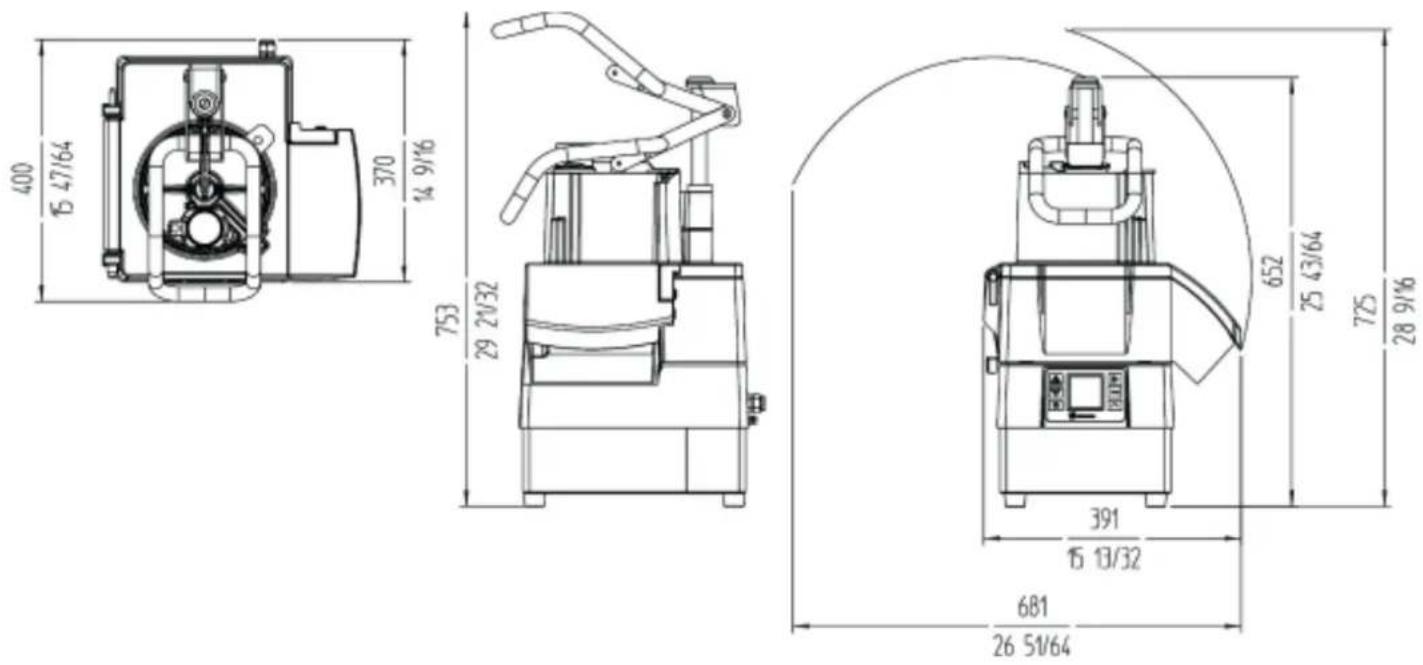
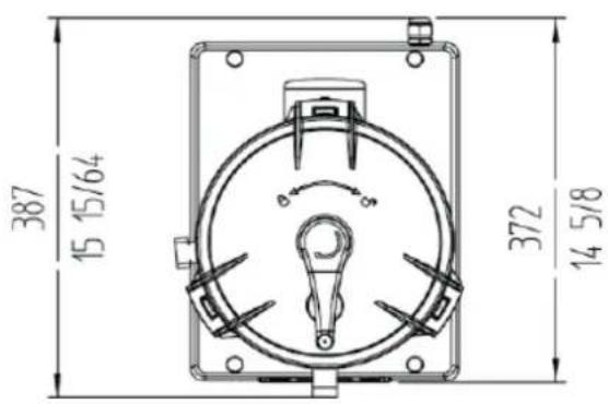
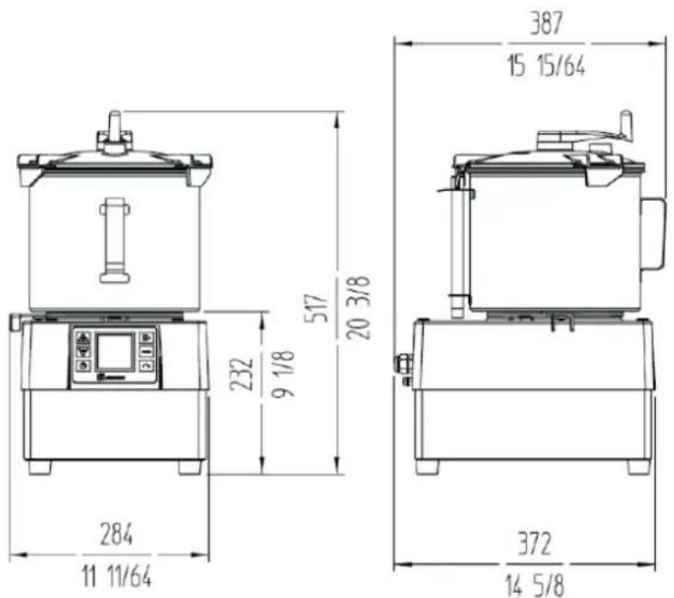
| External dimensions-Width 389 mm. / 15 5/16"- Depth 409 mm. / 16 1/8"- Heigth 565 mm. / 22 3/8" | |
| Net weight 20 kg. / 55.11 lbs. | |
CK-45V / CK-48V / CA-4V
| PROPERTIES CK-45V / CK-48V / CA-4V | |
| Output / hour 200 / 375 kg. - 441 / 826.7 lbs. | |
| Electrical power supply 230V / 50-60 Hz / 1~ | 120V / 50-60 Hz / 1~ | |
| Electric power 1500 W - 2 HP | 2200 W - 3 HP | |
| Variable speed (rPm) 300 - 3000 | |
| External dimensions- Wildth 389 mm. / 15 5/16"- Depth 400 mm. / 15 3/4"- Heigth 667 mm. / 26 3/8" | |
| Net weight 20 kg. / 44 lbs. | |
CK-35V / CK-45V / KE-5V
text_image
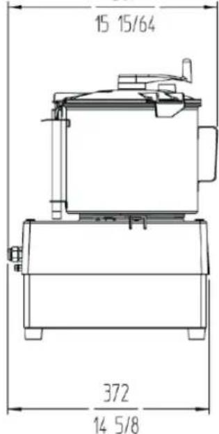
387 15 15/64 372 14 5/8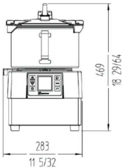
text_image
469 18 29/64 283 11 5/32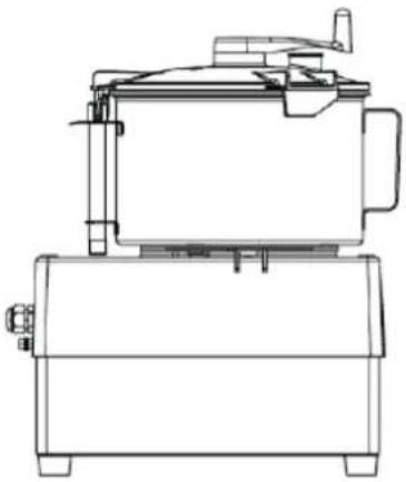
natural_image
Technical line drawing of a mechanical device with no visible text or symbolsCK-38V / CK-48V / KE-8V
text_image
387 15 15/64 232 9 1/8 517 20 3/8 284 11 11/64 372 14 5/8| PROPERTIES CK-35V / CK-38V / KE-5V | |
| Output / hour - | |
| Electrical power supply 230V / 50-60 Hz / 1~ | 120V / 50-60 Hz / 1~ | |
| Electric power 1500 W - 2 HP | 2200 W - 3 HP | |
| Variable speed (rPm) 300 - 3000 | |
| Tank capacity 5 L / 5 4/32 qt. | |
| Tank dimensions ø240 x 150h | |
| External dimensions-Width 389 mm. / 15 5/16"- Depth 400 mm. / 15 3/4"- Heigth 667 mm. / 26 3/8" | |
| Net weight 20 kg. / 44 lbs. | |
ABB. 1
natural_image
Prohibition sign showing a device with no visible text or symbols, crossed out by red prohibition lines (no text or symbols on the device itself)natural_image
Technical line drawing of a mechanical device with no visible text or symbolsCK-38V / CK-48V / KE-8V
text_image
284 11 11/64 232 9 1/8 517 20 3/8 387 15 15/64 372 14 5/8FIG 3 - Description technique
FIG 4 - Description technique
FIG 5 - Description technique
natural_image
Prohibition sign showing a device with no visible text or symbols, crossed out by red prohibition lines (no text or symbols on the device itself)natural_image
Technical line drawing of a mechanical device with no visible text or symbolsCK-38V / CK-48V / KE-8V
text_image
284 11 11/64 232 9 1/8 517 20 3/8 387 15 15/64 372 14 5/8natural_image
Prohibition sign showing a device with no visible text or symbols, crossed out by red prohibition lines (no text or symbols present)natural_image
Technical line drawing of a mechanical device with no visible text or symbolsCK-38V / CK-48V / KE-8V
text_image
284 11 11/64 232 9 1/8 517 20 3/8 387 15 15/64 372 14 5/8Limpeza do acessório "Cutter" (CK-35V/38V, CK-45V/48V e KE-5V/8V):
natural_image
Prohibition sign showing a device with no visible text or symbols, crossed out by red prohibition lines (no text or symbols present)natural_image
Prohibition sign showing a device with no visible text or symbols, crossed out by red prohibition lines (no text or symbols on the device itself)USUNAĆ PROGRAM (C1, C2, C3 ITD.)
natural_image
Prohibition sign showing a device with no visible text or symbols, crossed out by red prohibition lines (no text or symbols on the device itself)natural_image
Technical line drawing of a mechanical device with no visible text or symbolsCK-38V / CK-48V / KE-8V
text_image
284 11 11/64 232 9 1/8 517 20 3/8 387 15 15/64 372 14 5/8| EIGENSCHAPPEN CK-35V / CK-38V / KE-5V | |
| Productie / uur - | |
| Elektrische voeding 230V / 50-60 Hz / 1~ | 120V / 50-60 Hz / 1~ | |
| Elektrisch vermogen 1500 W - 2 cv | | 2200 W - 3 cv |
| Variabele snelheid (TPM) 300 - 3000 | |
| Tankinhoud 5 l. / 5 4/32 qt. | |
| Afmetingen tank in mm ø240 x 150h | |
| Uitwendige afmetingen-Breedte 389 mm. / 15 5/16 "-Diepte 400 mm. / 15 3/4 "-Hoogte 667 mm. / 26 3/8 " | |
| Nettogewicht 20 kg / 44 lbs. | |


SAMMIC
AENOR

Empresa Registrada ER:04371196


SAMMIC, S.L. Basarte, 1 - 20720 AZKOITIA - www.sammic.com
07-25 -2054027/2
CK-35V / CK-45V / KE-5V
CK-38V / CK-48V / KE-8V
text_image
15 15/64 372 14 5/8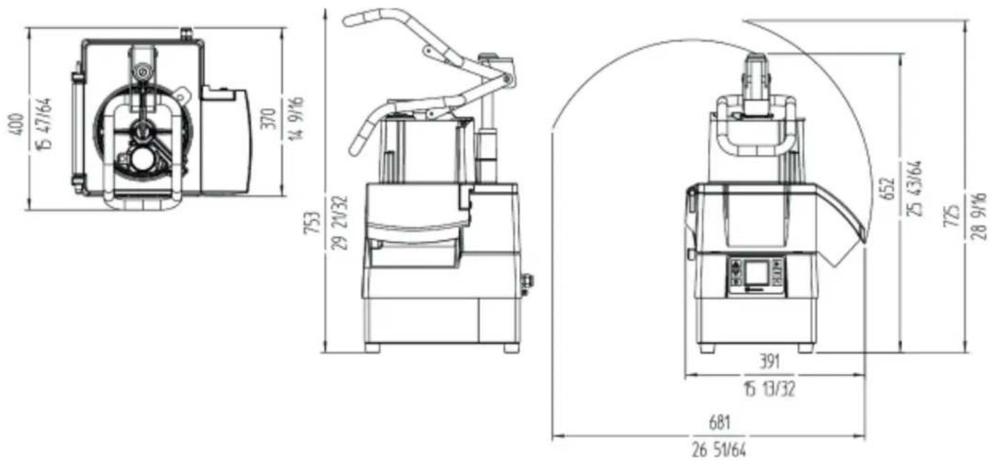
text_image
Prohibition sign showing a device crossed out by a red circle, indicating no protection or disapproval.text_image
A O M L K N J I B C E D F Y G HCK-35V/CK-45V/KE-5V/CK-38V/CK-48V/KE-8V (5 الشكل)
CK-45V/CK-48V/CA-4V (4 الشكل)
text_image
V U T S W X F D H Y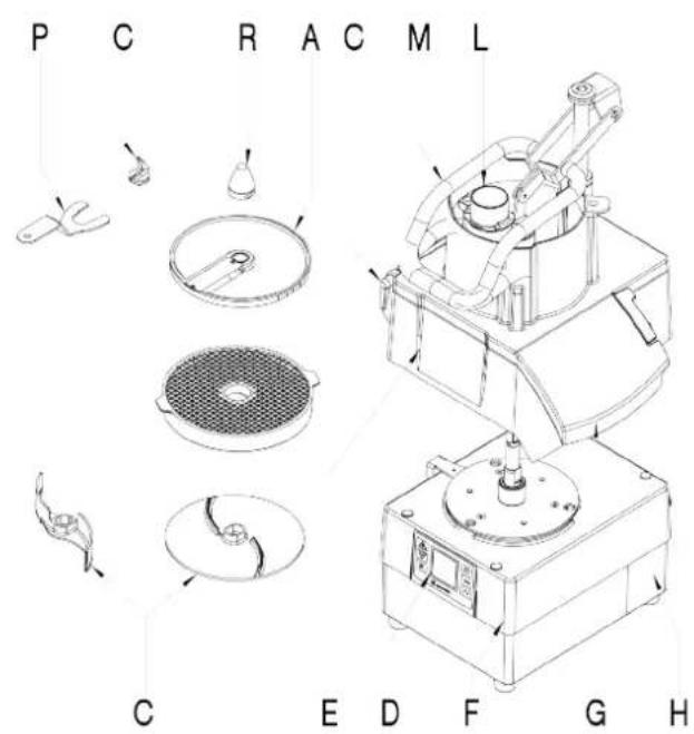
text_image
P C R A C M L C E D F G H(1 الشكل)
text_image
1 2 3 4 5 6 7 8 9 10 88 88:88 RPM 88:88"(2 alشكل)