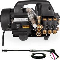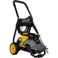
P2314EN - Pressure washer BE Power Equipment - Free user manual and instructions
Find the device manual for free P2314EN BE Power Equipment in PDF.


| Product Type | Electric Pressure Washer |
| Brand | BE Power Equipment |
| Model | P2314EN |
| Power Supply | 120 V, 60 Hz, grounded outlet |
| Max. Inlet Water Pressure | 150 PSI |
| Main Functions | High-pressure washing, detergent application, foam, rinsing |
| Included Nozzles | Rotating nozzle, quick-connect nozzles 0°, 15°, 25°, 40° (4 pieces) |
| Foam Cannon | Yes, with concentration adjustment |
| Spray Gun | With safety lock |
| Lance | 1 lance included |
| High Pressure Hose | Included, length not specified |
| Safety Device | Ground Fault Circuit Interrupter (GFCI), trigger lock |
| Maintenance | Regular nozzle cleaning, garden hose filter, use of pump protector for storage |
| Spare Parts | Nozzles, O-rings, hose, gun, lance, foam cannon (part numbers available) |
| Warranty | 1 year limited |
| Customer Service | 1-866-850-6662, Mon-Fri 8am-4:30pm CST |
Frequently Asked Questions - P2314EN BE Power Equipment
User questions about P2314EN BE Power Equipment
0 question about this device. Answer the ones you know or ask your own.
Ask a new question about this device
Download the instructions for your Pressure washer in PDF format for free! Find your manual P2314EN - BE Power Equipment and take your electronic device back in hand. On this page are published all the documents necessary for the use of your device. P2314EN by BE Power Equipment.
USER MANUAL P2314EN BE Power Equipment
natural_image
Exterior view of a modern electric water heater with adjustable arm and wheels (no visible text or symbols)96399-LJP2314EN
2,300 PSI ELECTRIC PRESSURE WASHER OPERATOR'S MANUAL
Congratulations on your purchase of a BE Power Equipment pressure washer. You can be confident that this pressure washer is constructed and tested with optimum performance and quality in mind.
Reading this manual will help get you the best results for set-up, operation, maintenance and avoid personal injury or damage to your machine. By knowing how best to operate this machine, you will be better positioned to show others who may also operate the unit.
All the information in this manual is based on the latest product information available at the time of printing. BE Power Equipment reserves the right to make changes at any time without notice or incurring any obligation.
Owner/Operator Responsibility
The owner/operator must have a thorough understanding of the operation, maintenance and dangers associated with using this machine. It must be understood that it is ultimately up to the owner/operator to safely use this machine as outlined in this manual.
This manual is considered a part of the machine and needs to be kept in a safe location. If the machine is resold or given to someone else, this manual needs to be included.
Record Identification Numbers
It is recommended that you record the product identification numbers in this manual. These numbers are important to have on hand if you need to contact technical support (1-866-850-6662). The model and serial number can be found on the box and on decal on the machine.
PRODUCT IDENTIFICATION
Model Number: P2314EN
Date of Purchase:
Dealer Name:

bepowerequipment.com
TABLE OF CONTENTS
Product Specifications.... 3
Package Contents 4
Hardware Contents.... 4
Safety Information 5
Assembly Instructions.... 7
Operating Instructions 12
Care and Maintenance 15
Pump Saver.... 16
Troubleshooting.... 17
Limited Warranty 18
Replacement Parts List 19

WARNING
ADVERTENCIA • AVERTISSEMENT
Cancer and Reproductive Harm
www.P65Warnings.ca.gov
PRODUCT SPECIFICATIONS
SPECIFICATIONS
| Model Max P | SI(lbs/sq. in.) | Max GPM(Gal/per min) | Cold Water | Volts Frequency(Hz) | Amps Weight (lbs.) |
| P2314EN | 2300 1.7 | √ | 120 60 13 31.1 |
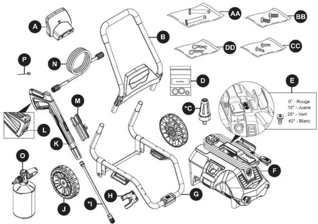
PACKAGE CONTENTS
text_image
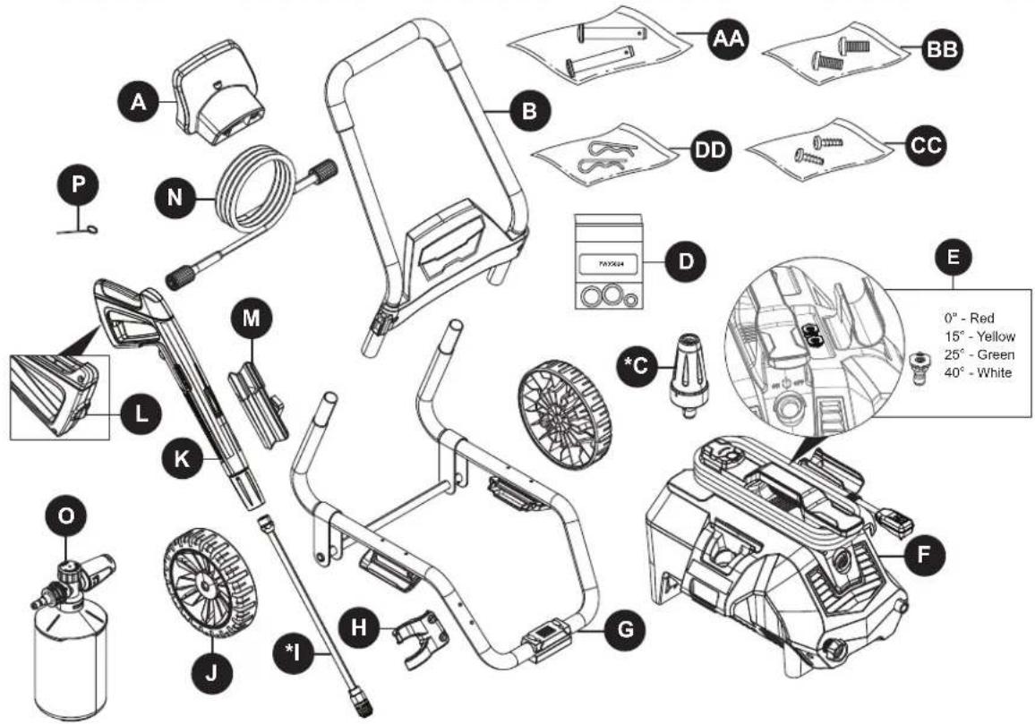
Exploded view diagram of a gas washing machine with labeled parts and color-coded zones for installation.| PART DESCRIPTION QUANTITY | ||
| A Hose Holder | 1 | |
| B Handle | 1 | |
| *C | Rotary Nozzle | 1 |
| D O-Ring Replacement Kit | 1 | |
| E Quick Connect Nozzles | 4 | |
| F Power Washer Unit | 1 | |
| G Lower Frame | 1 | |
| H Nozzle Holder | 1 | |
| *I Extension Lance | 1 | |
| J | Wheels | 2 |
| PART DESCRIPTION QUANTITY | ||
| K Spray Gun 1 | ||
| L Spray Gun Trigger Lock 1 | ||
| M Spray Gun Holster 1 | ||
| N High Pressure Hose 1 | ||
| O High Pressure Foam Cannon | 1 | |
| P Nozzle Cleaning Wire | 1 | |
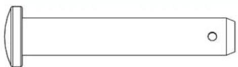
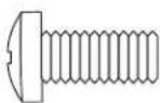
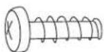
| AA | Axle Pins | 2 |
| BB | Screws | 2 |
| CC | Screws | 2 |
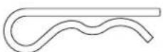
| DD | Cotter Pins | 2 |
*Packaged on the power washer unit.
HARDWARE CONTENTS
natural_image
Simple line drawing of a cylindrical object with a flanged top and a small circular hole at the end (no text or symbols)
Axle Pins Qty. 2
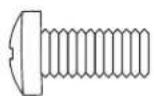

Screws Qty. 2
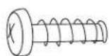

Screws Qty. 2
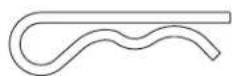

Cotter Pins Cant. 2

bepowerequipment.com
SAFETY INFORMATION
Please read and understand this entire manual before attempting to assemble and operate the product.
This manual contains information that relates to
PROTECTING PERSONAL SAFETY and PREVENTING
EQUIPMENT PROBLEMS. It is very important to read this manual carefully and understand it thoroughly before using the product. The symbols listed below are used to indicate this information.

DANGER
Potential hazard that will result in serious injury or loss of life.

WARNING
Hazard that could result in serious injury or loss of life.

CAUTION
Potential hazard that may result in moderate injury or damage to equipment.
Note: The word "Note" is used to inform the reader of something the operator needs to know about the tool.

NING
To reduce the risk of injury, the user must read and understand the instructions before using this product.
- Warning – When using this product, basic precautions should always be followed, including the following.
- Read all the instructions before using the product.
- Know how to stop the product and bleed pressures quickly. Be thoroughly familiar with the controls.
- Keep operating area clear of persons.
- Do not overreach or stand on unstable support. Keep good footing and balance at all times.
- Follow the maintenance instructions as specified in the manual.
- To avoid personal injury and/or damage to property and to maximize your power washer experience, carefully follow all of the safety tips, instructions, warnings and safeguards and become familiar with all of the controls. Be sure you know how to quickly bleed off the pressure from all parts of your power washer and how to turn off the power washer.
-
This power washer conforms to CSA and other safety and consumer standards. DO NOT modify or rebuild any part of your power washer.
-
DO NOT use your power washer when you are under bepowerequipment.com
the influence of alcohol or drugs. Use this power tool carefully and only when you are alert.
- Watch your balance and footing while using your power washer. Surfaces become slippery when wet and are extra slippery when using a detergent or cleaner.
- NEVER operate the power washer in bare feet, sandals, or open-toed shoes.
- When using the power washer near children, make sure they are closely supervised by an adult to avoid injury. NEVER let a child use the power washer.
- Keep fingers, hands, feet and any part of your body clear of the stream of high pressure water. The powerful spray can cause blindness or blast holes in the skin. It can break a window if you are too close when you pull the trigger on the spray gun.
- ALWAYS wear eye protection to prevent injury to eyes when operating the power washer.
- To avoid mishaps or injury, ALWAYS use the trigger safety lock when not using the power washer even if only stopping briefly.
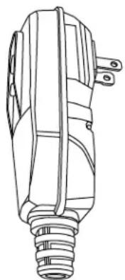
- The power washer is equipped with a Ground Fault Circuit Interrupter (GFCI) (For US unit only) which greatly reduces the chance of electric shock while the unit is in use. If replacement of the plug or cord is needed, use only identical replacement parts.
- Point the spray gun in a safe direction when beginning a power washer session.
- Warning-NEVER spray directly at a person, animal, electrical device or the unit itself.
- When first using the spray gun, hold the spray gun and lance with two hands when pulling the trigger (one hand to pull the trigger and the other to stabilize the gun assembly) until you get used to the "kickback" from the spray gun.
- When you press the power switch to turn off the power washer, waterpressure may remain in the system. To discharge the pressure, point thespray gun in a safe direction and pull the trigger.
- NEVER spray flammable liquids.
- NEVER use the power washer in areas that contain combustible dust, liquids or vapors.
- Avoid contact of the pressure hose with sharp objects and examine the hose regularly. Replace if damaged. Due to the high pressure involved, it cannot be repaired if cut or damaged.
- Only use detergent specifically formulated for power washers and follow instructions on the detergent's label. Dish or laundry soap is too thick and will clog the nozzle of your foam cannon.
- Protect eyes, lungs, and skin from exposure to

SAFETY INFORMATION
detergent.
- Warning-If connection is made to a potable water system, the system Should be protected against backflow.
CAUTION
Store the power washer indoors to prevent the water in the unit from expanding under freezing conditions. When the water freezes and expands, your power washer will be damaged and become inoperable. Or, if storing outdoors, it is recommended you use pump saver (not included) to protect pumps.
- NEVER use hot water with your power washer. It will overheat and damage the high pressure pump.
- NEVER leave the power washer unattended while it is powered "ON".
- ALWAYS turn the water supply on before turning the power washer power to on. Running the pump dry will cause damage to the internal components.
-
NEVER use a water supply to your power washer that exceeds 150 PSI maximum.
-
NEVER disconnect the high pressure hose from the power washer while the system is pressurized.
- NEVER permanently engage the trigger mechanism on the spray gun.
- NEVER operate the power washer unless all components are properly and securely connected.
- NEVER allow the power washer pump to run for more than one minute after you have turned off the water supply. This can cause the motor and pump to overheat and fail.
- NEVER use lances or other parts that are not compatible for this specific unit.
- NEVER use an extension power cord since it defeats the effectiveness of the GFCI (For US unit only) and increases the chance of electrocuting the operator.
- NEVER spray any electrical outlet with your power washer.
- Inspect the power cord before using. DO NOT use it if it is damaged.
- Stay alert - watch what you are doing.
KEEP THESE INSTRUCTIONS FOR FUTURE REFERENCE.
Ground Fault Circuit Interrupter Protection (For US unit only):
This pressure washer is equipped with a ground-fault circuit-interrupter (GFCI) built into the plug of the power-supply cord. This device provides additional protection from the risk of electric shock. Should replacement of the plug or cord become necessary, use only identical replacement parts that include GFCI protection.
This product must be grounded. If it should malfunction or breakdown, grounding provides a path of least resistance for electric current to reduce the risk of electric shock. This product is equipped with a cord having an equipment-grounding conductor and a grounding plug. The plug must be plugged into an appropriate outlet that is properly installed and grounded in accordance with all local codes and ordinances.
DANGER – Improper connection of the equipment-grounding conductor can result in a risk of electrocution. Check with a qualified electrician or service personnel if you are in doubt as to whether the outlet is properly grounded. Do not modify the plug provided with the product – if it will not fit the outlet, have a proper outlet installed by a qualified electrician. Do not use any type of adaptor with this product.
natural_image
Line drawing of a mechanical component with no visible text or symbols
bepowerequipment.com
PREPARATION
Before beginning assembly of product, make sure all parts are present. Compare parts with package contents list and hardware contents list. If any part is missing or damaged, DO NOT attempt to assemble the product. Please call customer service at 1-866-850-6662 for assistance.
Estimated Assembly Time: 5 minutes.
Tools Required for Assembly (not included): Phillips screwdriver.
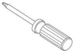
natural_image
Line drawing of a screwdriver with a flat blade and threaded end (no text or symbols)ASSEMBLY INSTRUCTIONS
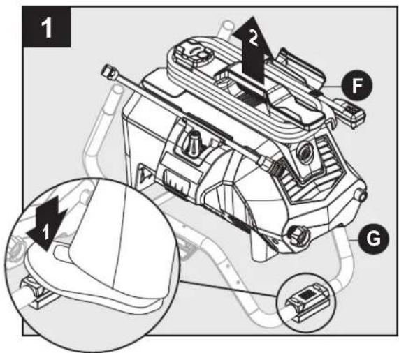
text_image
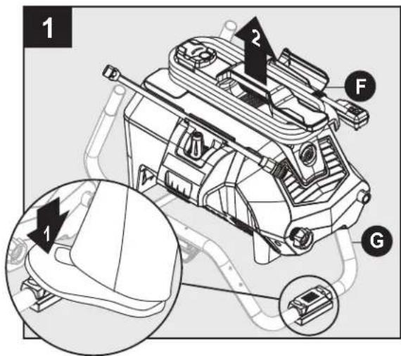
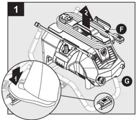
1 2 F G 1Place a foot on the pad at the front of the lower frame (G) and then lift the power washer unit (F) off the frame. Set pressure washer (F) to the side.
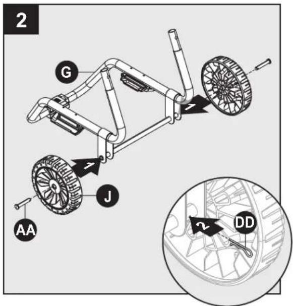
text_image
2 G J AA DDFrame Assembly
Install axel pins (AA) and wheels (J) to lower frame (G). Secure with cotter pins (DD).
Hardware Used:

Axle Pins
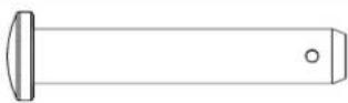
x 2

Cotter Pins
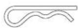
x 2
ASSEMBLY INSTRUCTIONS
text_image
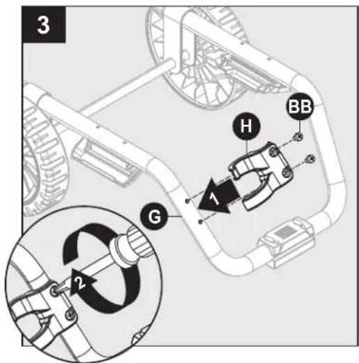
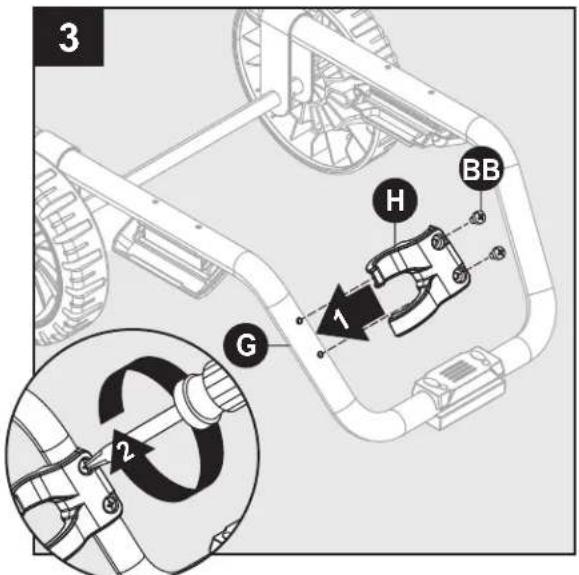
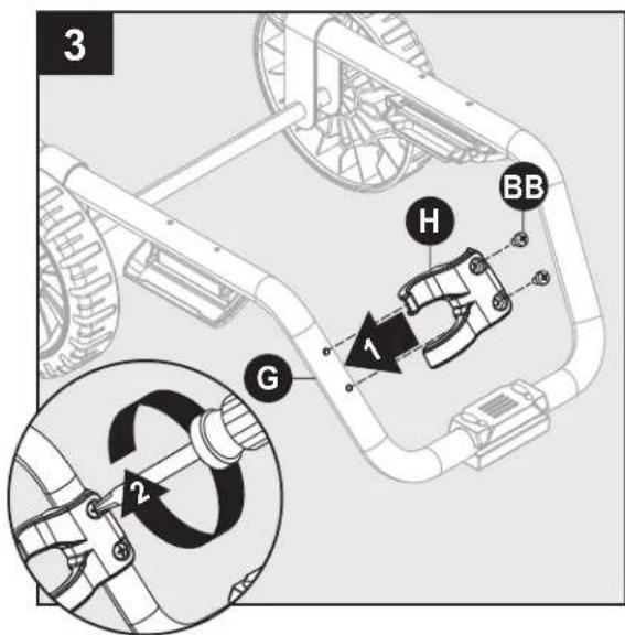
3 H BB 1 G 2Install nozzle holder (H) to lower frame (G). Secure with two screws (BB).
Hardware Used:
BB Screws
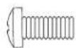
x 2
text_image
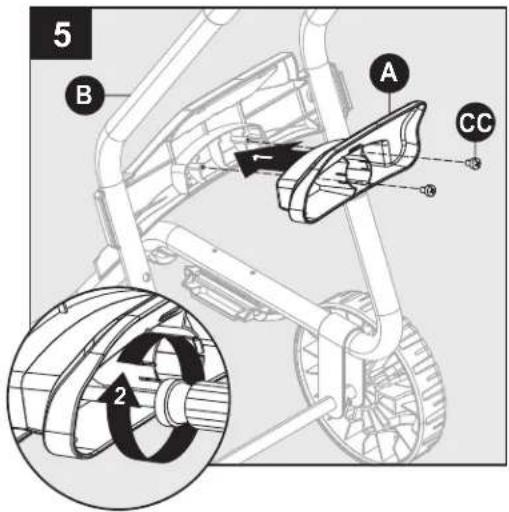
5 B A CC 2Install hose holder (A) onto back side of upper handle (B). Secure with two screws (CC).
Hardware Used:
CC
Screws
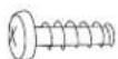
x 2
BE
text_image
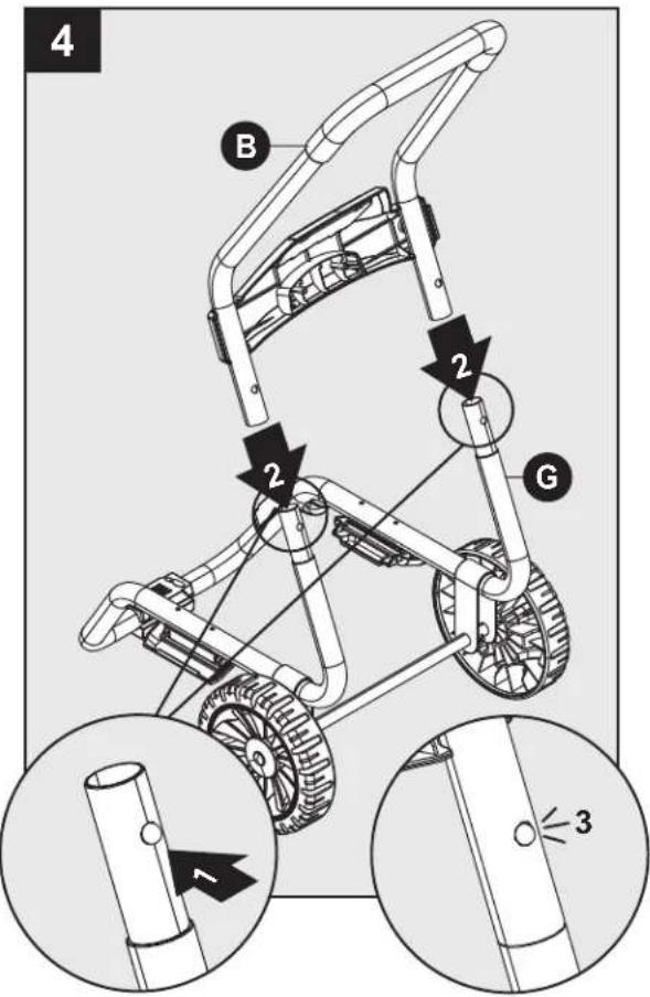
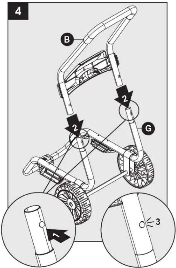
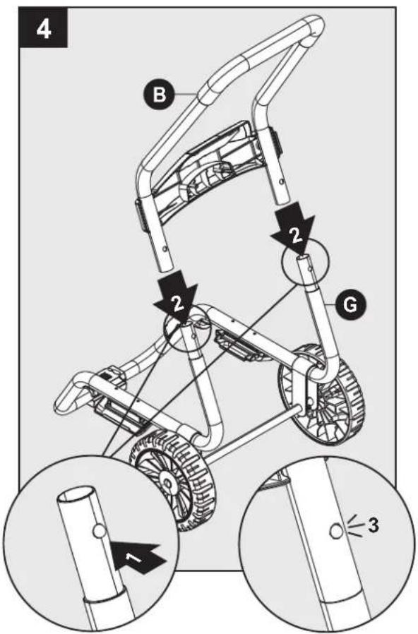
4 B 2 2 G 1 3Press buttons on lower frame (G) extensions and install handle (B). Lower frame extensions will click when handle is in proper position.
text_image
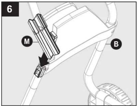
6 M BSlide spray gun holster (M) into place on the upper handle (B).
bepowerequipment.com
ASSEMBLY INSTRUCTIONS
text_image
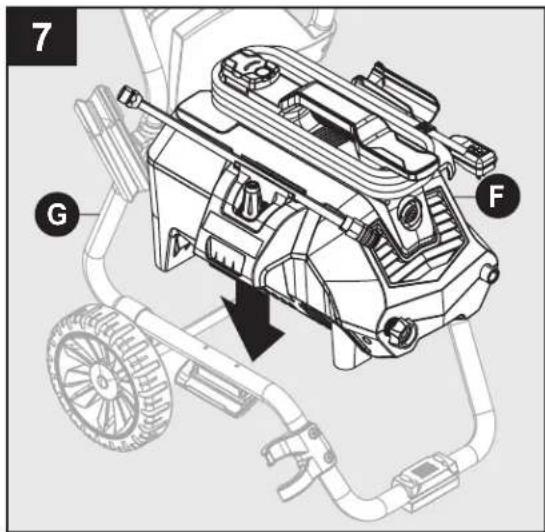
7 G FPlace power washer unit (F) into position on the lower frame (G).
text_image
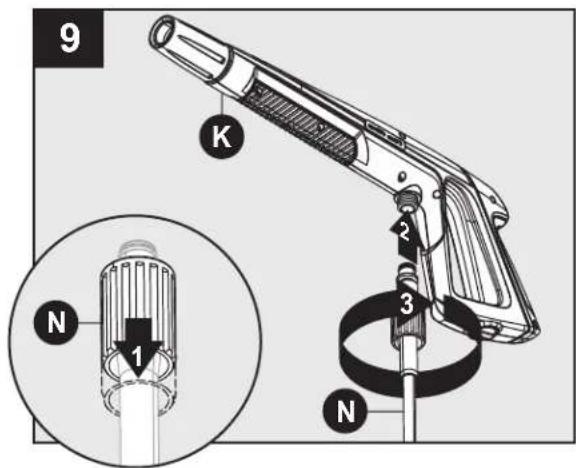
9 K N 1 2 3 NPull back on collar at one end of high pressure hose (N). Push firmly to connect hose to spray gun (K). Twist collar to secure. Confirm hose is locked into spray gun by slightly pulling on them. The hose is now securely attached to spray gun.
text_image
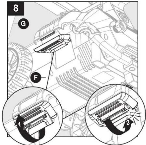
8 G F 1 2Pull upward on latches that are located on sides of lower frame (G). Once upper latch is flush with the lower lip, push down until lower latch clicks into place.
text_image
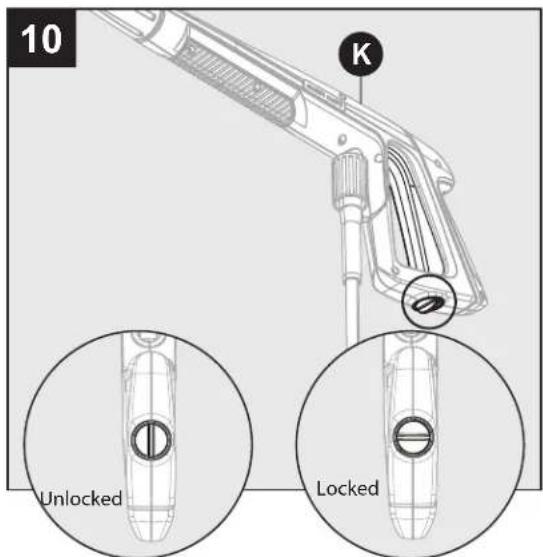
10 K Unlocked LockedLocking Spray Gun (before Lance installation) To lock trigger of spray gun (K), point gun away from you and turn dial to lock ("3" and "9" position). Squeeze or pull trigger to make sure it is locked. Always leave in locked position when not in use. This ensures the gun is in "safe" mode until it is ready for use. Turn dial to unlock ("12" and "6" position) to release spray gun trigger.
Note: The trigger lock prevents trigger from being accidentally engaged.
ASSEMBLY INSTRUCTIONS
text_image
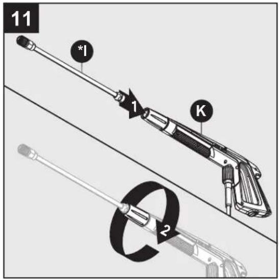
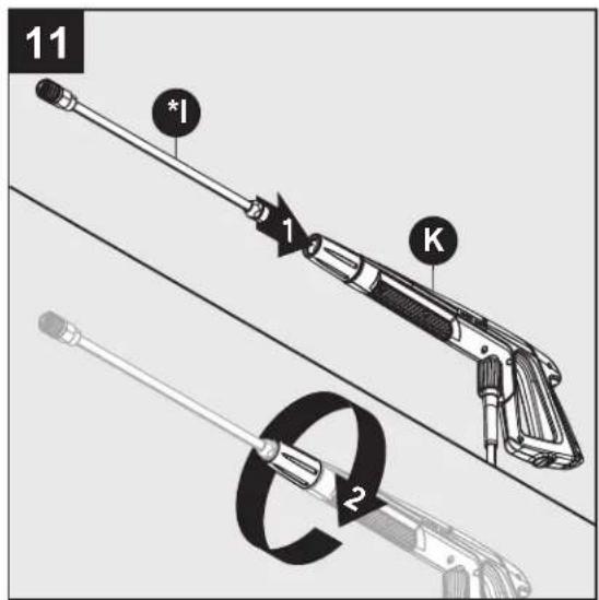
11 *I 1 K 2Extension Lance Installation
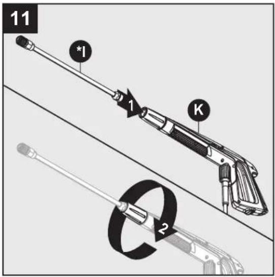
While spray gun (K) is in the locked position, insert lance (*I) into the end of spray gun by inserting and turning clockwise until fully in place. To remove, turn counterclockwise.
text_image
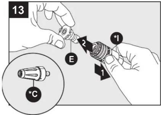
13 E 2 *I 1 *CTo remove nozzle (E) and Rotary nozzle (*C), pull back on collar of lance (*I) and pull out nozzle.
text_image
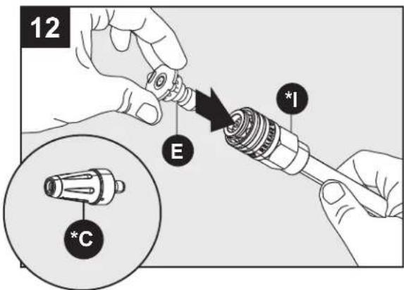
12 E I *CAttach nozzle (E) and Rotary nozzle (*C) into end of lance (*I) by pressing selected nozzle into place. It will make a "click" sound when firmly in place.
Note: Always push safety lock button to lock trigger when changing lances and nozzles to ensure that they do not accidentally eject with force during removal.
text_image
14 1 O 2 750ml 0.5ml 450ml 350ml 1.5mlFoam Cannon Installation
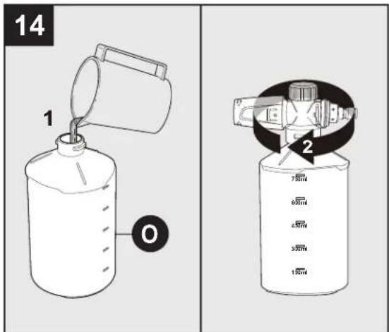
The foam cannon (O) comes with a straw which is fitted into high pressure top. If you do not see the straw, look inside the foam cannon and attach it to the high pressure top. When using foam cannon, fill it with a properly formulated detergent or cleaner with a water ratio according to instructions on the container.
- DO NOT use thick or gel-like detergents as they will clog the foam cannon and can cause damage.

bepowerequipment.com
ASSEMBLY INSTRUCTIONS
text_image
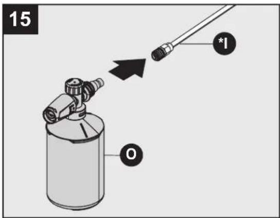
15 *1 OAttach Foam Cannon (O) into end of lance by pressing cannon into place. It will make a "click" sound when firmly in place.
Note: Always lock spray gun when changing the foam cannon to ensure it does not eject with force.
- When using the foam cannon, fill it with a properly formulated detergent or cleaner with water ratio according to instructions on the container.
text_image
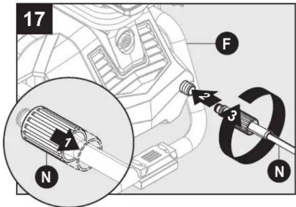
17 F 2 3 1 N NPull back on collar at the other end of high pressure hose (N). Push firmly to connect hose to power washer unit. Twist collar to secure. Confirm hose is locked into power washer unit by slightly pulling on hose. The hose is now securely attached.
natural_image
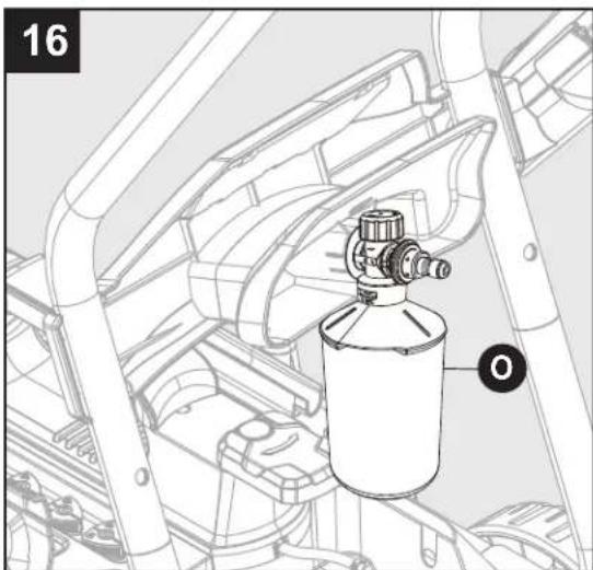
Technical line drawing of a mechanical assembly with a cylindrical component and pipe fittings (no text or symbols)Foam Cannon Storage Store the foam cannon (O) on the back of the power washer unit (C).
text_image
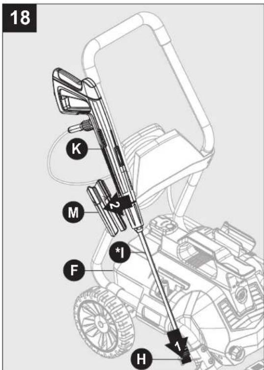
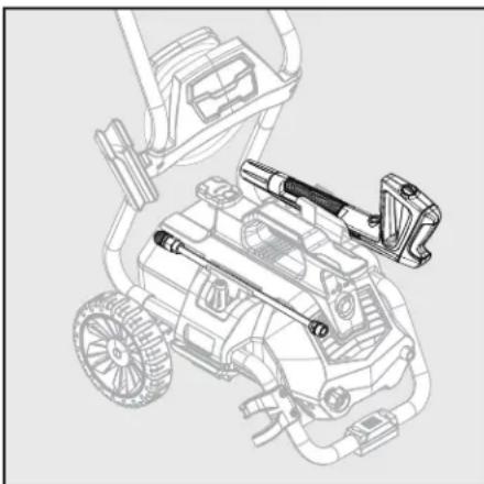
18 K M *1 F H 1Insert extension lance (*I) into nozzle holder (H), and press spray gun (K) with extension lance (*I) into spray gun holster (M).
ASSEMBLY INSTRUCTIONS
text_image
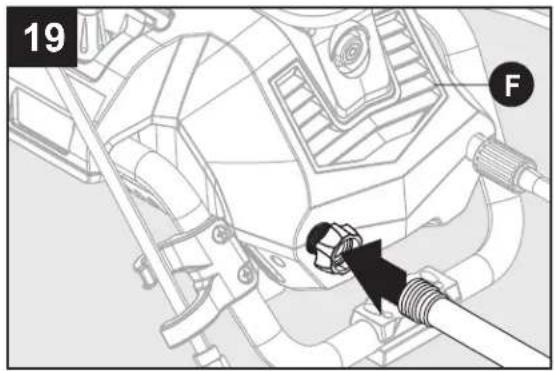
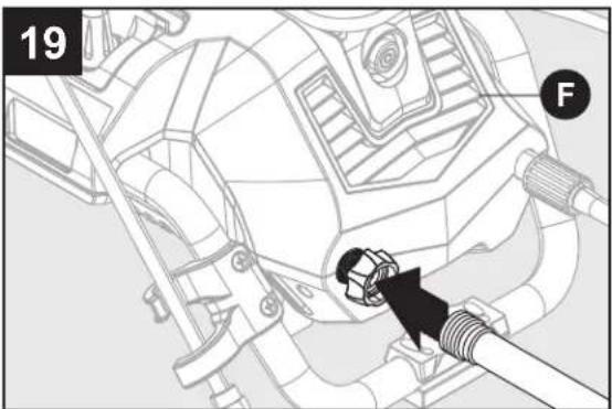
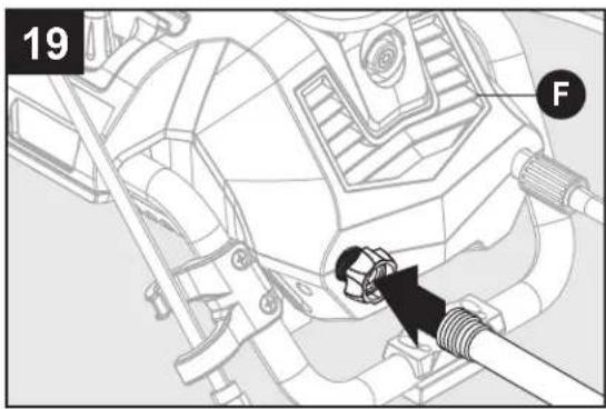
19 FAttach a garden hose to built in garden hose adapter. The water is now connected to your power washer.
Note: Flush out garden hose before connecting to garden hose adapter
You have now completed the assembly and are ready to begin using your electric power washer. Read and observe all safety instructions.
OPERATING INSTRUCTIONS
natural_image
Diagram of a mechanical assembly with no visible text or symbols- Make sure the power switch is off (light will be off).
- Unwind the power cord completely and plug into a grounded 120 volt outlet.
- Turn on water supply at the faucet to completely open.
text_image
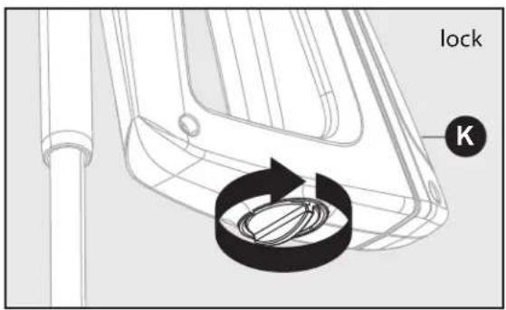
lock K- Turn the safety lock button on the spray gun to unlocked. While pointing the spray gun in a safe direction, squeeze the trigger on the spray gun until there is a steady stream of water, letting the water and air out of the hose.

bepowerequipment.com
OPERATING INSTRUCTIONS
text_image
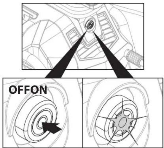
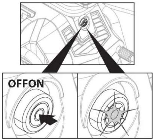
OFFON- Push the power button to turn the unit on (Green power light will turn on). The unit will turn on for 1 - 2 seconds and shut off. This is a normal function of the auto start feature.
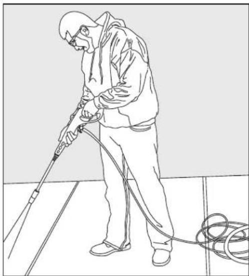
- Squeeze the spray gun trigger to begin pressure washing.
- Begin power washing by squeezing the trigger on the spray gun all the way into the handle.
- Release the spray gun trigger to stop the power washer.
- Allow the motor to come to a complete stop before squeezing the trigger again.
- Squeezing rapidly will cause the auto start feature to miss an on/off cycle that may prevent it from turning on while squeezing trigger after rapid squeezing. Use slow, deliberate trigger pulls to avoid this.
natural_image
Line drawing of a person cleaning a tiled floor with a hose and coiled cable (no text or symbols)• Always test a small area to avoid chance of damaging the surface.
bepowerequipment.com
text_image
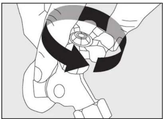
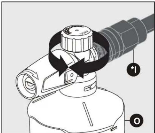
Technical diagram of a mechanical device with labeled parts and directional arrows indicating rotation or movement.Adjusting Soap Levels on Foam Cannon Twist knob to adjust the level of soap as indicated on the top of the Foam Cannon (O). Twist toward the higher concentration of bubbles for more soap, or the opposite direction for less.
natural_image
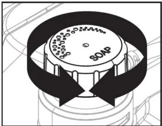
Diagram of a soap dispenser with black arrows indicating rotation or movement (no text or symbols)- The power washer will pull a ratio of water to detergent of 10:1 or 10 parts water to 1 part detergent. The detergent concentration can be adjusted by turning the detergent knob on the top of the machine. Turn it left for more concentration or turn it right for less concentration.
OPERATING INSTRUCTIONS
text_image
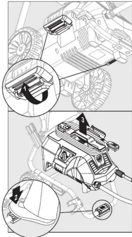
Technical diagram showing mechanical assembly with numbered components and close-ups of parts in different views.Removing Power Washer Unit from Frame for Handheld Operation
- Locate latches on the lower side of frame. Unlock latches by pulling downward on the latches. Place a foot on the pad at the front of the lower frame and then lift the power washer unit off the frame.
Operation Tips
- Note: Test the GFCI (For US unit only) before each use:
- Plug GFCI into power outlet. Indicator should turn green to show that cord has power.
- Press test button, green indicator should turn off to verify that GFCI cut off power to the cord.
- Press reset button – green indicator should turn on to show that cord has power again.
-
When GFCI is working properly, green indicator will turn on when power is applied. If green indicator turns off, it has detected electric leakage and the GFCI cut off power to the appliance.
-
If you hear the motor run intermittently when the trigger is not being squeezed, that is normal.
The pump is priming itself so it is ready to operate when the trigger is squeezed. Turn off the power washer if not being used after five minutes. - The o-rings on the bayonet end of the nozzle should be cleaned regularly and lubricated with non-water soluble grease such as petroleum jelly (not included).
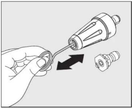
- Keep the nozzle cleaning wire for use in unclogging the nozzle. If you lose the cleaning wire, a straightened paper clip also works.
How to Avoid Damaging Surfaces
- Damage to surfaces being cleaned occurs because the impact force of the water pressure exceeds the durability of the surface. Bare wood can be penetrated, paint can be peeled off, etc. You can vary the force of your power washer by controlling:
- The angle of the surface being cleaned.
- The distance of the nozzle from the surface being cleaned.
- Never use a narrow high pressure stream of water on soft surfaces susceptible to damage.
- Use the 25" quick connect nozzle when cleaning windows. Squeeze the trigger and vary the spray pattern and angle until optimum cleaning efficiency is achieved. Using Power Cord
natural_image
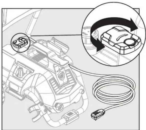
Technical diagram of a mechanical assembly with a magnified inset showing a component being connected to a cable (no text or symbols present)- Remove the power cord from the unit by swiveling the cord hook to the right or left. The power cord then can be slid off to either side of the power washer unit.
- Swivel cord hook back to center when ready to wrap the cord back into place for storage.

bepowerequipment.com
CARE AND MAINTENANCE
Detergents
- Use detergents designed for power washers. Hardware stores or home centers also have power washer detergents for different cleaning projects. The cleaning solution should be the consistency of water in order to prevent clogging your detergent bottle and nozzle.
- This system applies detergent under low pressure. The cleaning power of the detergents is enhanced when applied with low pressure and enough time is given to break down dirt and grime. The combination of low pressure and chemical action is very effective and can be better than scrubbing if applied properly. Always spray detergent on a dry surface. Do not pre-soak area. Wetting the surface first dilutes the detergent and reduces its cleaning ability. Do not allow detergent to dry on surface. On vertical surfaces being cleaned, apply detergent to lower surfaces and work your way up to prevent detergent from causing streaks in the dirt and grime. Rinse detergent by pressure washing from bottom up for same reason.
- If a stain is particularly tough, it may be necessary to reapply the detergent and use a bristled brush to scrub the stain. Subsequent power washing after brushing should successfully complete your cleaning job.
Cleaning Garden Hose Adapter
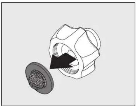
- The screen inside the adapter should be cleaned periodically. Remove it by dragging a thumb over the screen with enough pressure to pull the screen and washer out. Rinse it with clean water and then place it back in the adapter.
natural_image
Technical illustration of a mechanical component with a magnified inset showing internal threading (no text or symbols)Cleaning Nozzles
- A clogged or partially clogged nozzle can cause significant reduction of water pressure coming out of the nozzle and/or cause the unit to pulsate while spraying.
- Turn off the unit.
- Turn off the water supply to the unit.
- Relieve any pressure trapped in the hose by squeezing the trigger 2 - 3 times,
bepowerequipment.com
then lock the spray gun by turning the dial to lock ("3" and "9" position).
- Using the nozzle tip cleaner provided (or an unfolded paper clip), insert the wire into the nozzle hole and move back and forth until debris is dislodged.
- Back flush water through the nozzles using garden hose and highest pressure available (either standard water nozzle or use your thumb over the nozzle to create water pressure for back flush).
natural_image
Illustration of a hand holding a screwdriver with an arrow indicating the process (no text or symbols present)Storage
- When your pressure washer session has been completed, turn off the power switch. Unplug the power cord from the outlet. Turn off the water supply. Pull the trigger on the spray gun 2-3 seconds to drain out the excess water and to release any remaining water pressure. Do not allow the power washer to run with no water flowing through it.
- Remove high pressure hose from spray gun and unscrew the other end of the high pressure hose from the power washer.
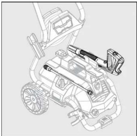
- Remove lance from the gun. Place the gun and lance in the holster on the sides.
• Make sure to discard any remaining detergent from the tank. Residual chemical will stick to the container which
natural_image
Technical line drawing of a mechanical device with wheels and a mounted component (no text or symbols)
CARE AND MAINTENANCE
could become contaminated, and can cause the detergent injector to clog and not function properly. Flush the tank and nozzle head with clear water to prevent clogging.
- Wind the power cord around the L-shaped hooks located on the top of the machine.
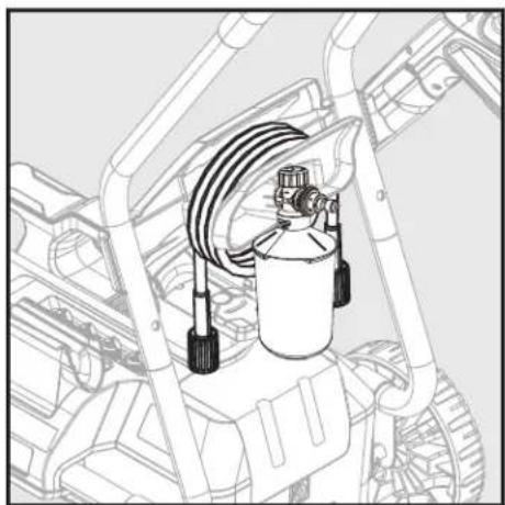
- The pressure hose is stored on the hose hook located on the back of the handle.
natural_image
Technical line drawing of a mechanical assembly with hoses and a central cylinder (no text or symbols)- The quick connect nozzles and rotary nozzle are stored on the nozzle holder located on both sides of machine.
natural_image
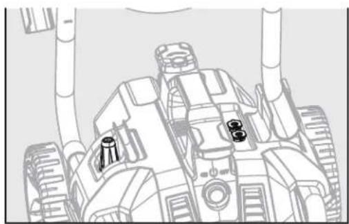
Line drawing of a military tank with visible turret and engine components (no text or symbols)- DO NOT store the power washer where it is exposed to freezing temperatures unless you use an antifreeze designed for pumps. Store the power washer indoors to prevent the water in the unit from expanding under freezing conditions. When the water freezes and expands, your power washer will be damaged and become inoperable. Or, if storing outdoors, it is recommended you use pump saver (not included) to protect pumps.
PUMP SAVER
Pump Saver is a product that protects and prolongs the life of the pump. This will keep the internal parts of the pump lubricated and protected from freezing while being stored in ALL climates. It also assists with protection from internal corrosion. The BE Power Equipment part number is: 85.490.046. Purchase at a BE Power Equipment retailer near you.
Pump Saver Instructions
Follow the previous storage instructions for your power To prevent staining, protect the surface under the power washer from any excess fluid. wear ear and eye protection when using this product.
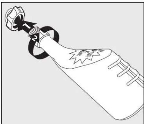
Turn unit off and disconnect the gun before adding pump saver. Unscrew threaded top from bottle to remove seal and reattach threaded top to bottle.
Remove black cap from bottle.
1) Place top of pump saver bottle onto the garden hose adapter.
2) Secure pump saver bottle by turning in a lockwise direction.

3) Turn the power on.
4) Squeeze bottle to help it into the pump.
5) Turn power off when pump saver exits the machine's water outlet.
Note: Instructions on Pump Saver Bottle are generic and not model specific.
natural_image
Line drawing of a bottle with a strap and ring, no text or symbols presentbepowerequipment.com
TROUBLESHOOTING
If you have any questions regarding the product, please call customer service at 1-866-850-6662.
| PROBLEM CORRECTIVE ACTION | |
| Unit will not turn on. | 1. Make sure the power washer is OFF. Plug in the electrical cord to a grounded 120 volt outlet (no electrical extension cord should be used). If the electrical cord will not plug into your outlet, your electrical outlet is not properly grounded and should not be used. Use another electrical outlet.2. If this did not correct the problem, try plugging into another electrical outlet and repeat the above procedure. If it is still not working, call Customer Service. 1-866-850-6662. |
| The high pressure (HP) hose will not connect/stay connected to the spray gun. Is this a spray gun problem? | 1. In most cases, the spray gun is not the problem. The problem is the rubber sleeve covering the fitting at the end of the high pressure hose. It has likely slipped up toward the metal tip. To fix: wiggle, twist and/or pull the rubber sleeve down until the entire tip is visible plus an 1/8 in. of the metal fitting below the tip. Now try to insert the hose tip into the spray gun. It should “click” into place and will not come out until the hose is released by pushing in the lever on the underside of the gun. You may cut away the end of the sleeve with a sharp knife if unable to move the sleeve down. Be careful not to cut or puncture the hose. |
| The unit is running but there is no water flow. | 1. Power should NOT be turned on until water comes through the spray gun. Doing so will damage the motor.2. Check the water source.3. Eject the nozzle from the lance to determine if clog is coming from the nozzle (If nozzle is clogged, see nozzle cleaning instructions under “Cleaning nozzles”).4. Take off the lance and just spray out of the spray gun. This will indicate if the problem is with the lance.5. Check Garden Hose Adapter for loose connection and the filter for debris. |
| Why is water leaking where the high pressure hose connects to the spray gun? | 1. Make sure there is an o-ring at the end of the metal tip of the high pressure hose. If no o-ring is present, the connection between the hose and spray gun will leak. O-Ring Replacement Kit (D) is included with purchase. |
| I can’t remove the lance from the spray gun. What should I do? | 1. All lances are attached and removed from the spray gun in the same manner. Insert the end of the lance into the spray gun. Press the spray gun and lance together (about a 1/8 in.) and turn the collar of the gun clockwise. The lance will lock in place. Remove the lance by reversing this procedure. Press the spray gun and lance together and turn counter clockwise. The lance will slide out.2. Hold the spray gun and lance in an upright position with the nozzle end on the floor. Push the whole assembly straight down to loosen the connection, and then follow the removal process again. You may also spray soapy water or a lubricant in the area where the lance connects to the spray gun. |
| The power washer turns on for 2 seconds, shuts off, and will not turn back on. Do I have a defective unit? | 1. When the water is connected, the accessories are assembled properly, and the power is turned on, the power washer may turn on for 1 - 2 seconds to prime the pump. It automatically shuts off and waits for the spray gun trigger to be pressed. When the trigger is pressed, water starts flowing through the pump. The water sensor in the pump “senses” the moving water and automatically turns the power washer on.2. Turn the power off, hold in the trigger on the spray gun so that you have a steady stream of water. While you are holding the trigger open on the spray gun, at the same time, turn the power on. |
LIMITED WARRANTY
BE Power Equipment Inc. warrants the original retail purchaser that this pressure washer is free from defects in material and workmanship for the periods set forth below. If defects are found in BE Power Equipment products within the limitations outlined in this warranty statement, BE Power Equipment, at its sole discretion, will repair or replace the product free of charge.
The warranty coverage is for one year and begins on the date of purchase by the end-user. Valid proof of purchase must be presented with the warranty claim.
This warranty is limited to defects that occurred during regular operational use. This warranty does not cover failures due to lack of service, negligence, abuse or misuse. Including, but not limited to, freezing damage, alterations, chemical deterioration, scale build-up, rust, corrosion, thermal shock, thermal expansion, transportation damage, oil changes, valve adjustments, fuel system maintenance or using incorrect repair parts. Furthermore, Using the wrong fuel, water or power supply is considered a form of misuse.
This warranty also does not cover normal wearing items such as O-rings, valves, seals, filters, sparkplugs or packings. These are considered to be maintenance items.
To obtain warranty, the claimant must take the product, with their original proof of purchase, to an authorized BE Power Equipment service center. These service centers are located on the website:
https://www.bepowerequipment.com/service-centers
If you cannot resolve the warranty claim satisfactorily, contact the BE Power Equipment Warranty Department (1-866-850-6662). Be prepared with details of the defect, proof of purchase, and model.
Please note: Power washers sent to the company without an RMA Number will NOT be accepted and will be shipped back at the expense of the sender.
REPLACEMENT PARTS LIST
For replacement parts, call our customer service department at 1-866-850-6662 8 a.m. - 4:30 p.m., PST, Monday - Friday.
text_image
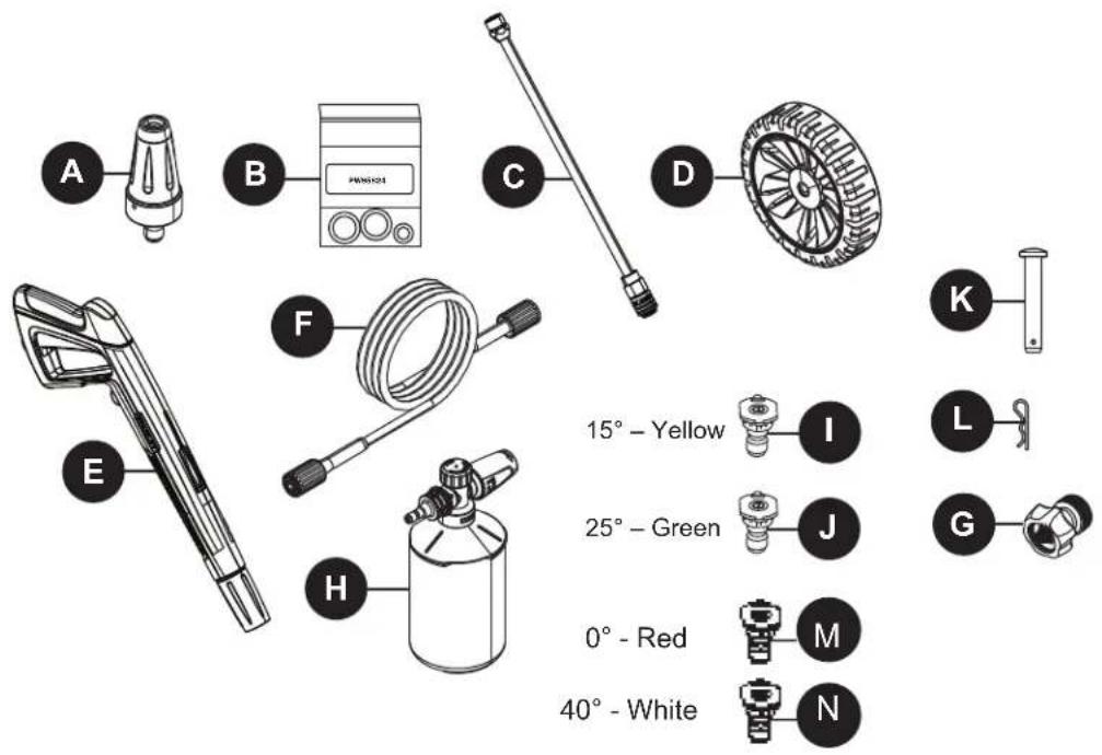
A B C D E F H 15° - Yellow 25° - Green 0° - Red 40° - White I J M N K L G| PART DESCRIPTION | PART DESCRIPTION | |
| A Rotary Nozzle | I Spray nozzle, 15° Yellow | |
| B O-Ring Replacement Kit | J Spray nozzle, 25° Green | |
| C Extension Lance | K Axle Pin | |
| D Wheel | L Cotter Pin | |
| E Spray Gun | M Spray nozzle, 0° Red | |
| F High Pressure Hose | N Spray nozzle, 40° White | |
| G Garden Hose Adapter | ||
| H High Pressure Foam Cannon | ||
Printed in China
BE POWER EQUIPMENT
natural_image
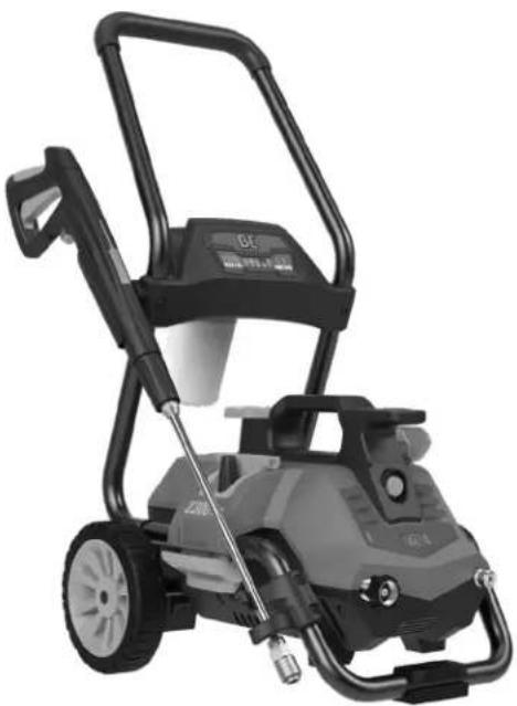
Exterior view of a modern electric water heater with adjustable arm and wheels (no visible text or symbols)96399-LJP2314EN
2,300 PSI LAVEUSE À PRESSION ÉLECTRIQUE MANUEL D'OPÉRATEUR
ELECTRIC PRESSURE WASHER OPERATOR'S MANUAL MANUAL DEL OPERADOR DE LA LAVADORA A PRESIÓN
BEPOWEREQUIPMENT
.COM
12.2021
TABLE DES MATIÈRES
Cancer and Reproductive Harm
www.P65Warnings.ca.gov
CARACTÉRISTIQUES DU PRODUIT
SPÉCIFICATIONS
| Modèle | PSI maximum(k/cm2)(lb/po2) | Débit maximum(Litre/min)(Gal./min) | Eau froide Volts Fréquence | Ampères | Poids(kg)(lb) | ||
| (Hz) | |||||||
| P2314EN 6730(2 300) | 6.4(1.7) | √ | 120 60 | 13 14.1 | (31.1) | ||

bepowerequipment.com
CONTENU DE L'EMBALLAGE
text_image
A P N L K M O J H I B D E 0° - Rouge 15° - Juane 25° - Vert 40° - Blanc AA BB DD CCnatural_image
Simple line drawing of a cylindrical object with a flanged end and a small circular hole at the top (no text or symbols)bepowerequipment.com
SAFETY INFORMATION
natural_image
Line drawing of a mechanical component with no visible text or symbols
PRÉPARATION
natural_image
Line drawing of a screwdriver with a flat blade and threaded end (no text or symbols)INSTRUCTIONS POUR L'ASSEMBLAGE
text_image
1 2 F G 1text_image
2 G J AA DDbepowerequipment.com
INSTRUCTIONS POUR L'ASSEMBLAGE
text_image
3 H BB 1 G 2bepowerequipment.com
text_image
4 B 2 2 G 3text_image
9 K 2 N 1 3 Ntext_image
8 G F 1 2bepowerequipment.com

INSTRUCTIONS POUR L'ASSEMBLAGE
text_image
11 *1 1 K 2text_image
12 E I *Cnatural_image
Technical line drawing of a mechanical assembly with a cylindrical component and curved components (no text or symbols)bepowerequipment.com
INSTRUCTIONS POUR L'ASSEMBLAGE
text_image
19 Fnatural_image
Diagram of a mechanical assembly with rotating components and directional arrows (no text or labels)natural_image
Line drawing of a person cleaning a tiled floor with a hose and coiled cable (no text or symbols)text_image
Diagram of a mechanical device with labeled parts and rotational arrows indicating motion or rotation.text_image
Technical diagram showing mechanical assembly with labeled parts and directional arrows indicating motion or assembly steps.bepowerequipment.com
MODE D'EMPLOI
natural_image
Technical diagram of a mechanical assembly with a close-up inset showing a cable being inserted into a component (no text or symbols present)natural_image
Technical illustration of a mechanical component with a magnified inset showing internal structure (no text or symbols)Nettoyage des buses
natural_image
Illustration of a hand holding a screwdriver with an arrow indicating tool direction (no text or symbols)Rangement
bepowerequipment.com
ENTRETIEN
natural_image
Technical line drawing of a mechanical device with hoses and components (no text or symbols)natural_image
Technical line drawing of a mechanical assembly with hoses and components (no text or symbols)natural_image
Line drawing of a robotic vehicle with visible gears and suspension components (no text or symbols)bepowerequipment.com
natural_image
Line drawing of a bottle with decorative knot and starburst pattern (no text or symbols)DÉPANNAGE
bepowerequipment.com
DÉPANNAGE
PROBLÈME MESURE CORRECTIVE
bepowerequipment.com
BE POWER EQUIPMENT
natural_image
Exterior view of a modern electric water heater with adjustable arm and wheels (no visible text or symbols)96399-LJP2314EN
2,300 PSI
MANUAL
DEL OPERADOR
Cancer and Reproductive Harm
www.P65Warnings.ca.gov
bepowerequipment.com
text_image
Exploded view diagram of a cleaning or cleaning device with labeled parts and a detailed inset showing interior details.natural_image
Simple line drawing of a cylindrical object with a flanged base and a small circular hole at the end (no text or symbols)
Perno de eje
Cant. 2

Tornillos
Cant. 2

Tornillos
Cant. 2

Pasador de chaveta
Cant. 2
bepowerequipment.com
natural_image
Technical line drawing of a mechanical component with threaded ends and a central shaft (no text or symbols)PREPARACIÓN
natural_image
Line drawing of a screwdriver with a flat tip and threaded shaft (no text or symbols)INSTRUCCIONES DE MONTAJE
text_image
1 2 F G 1text_image
2 G J AA DDbepowerequipment.com
text_image
3 H BB 1 G 2
x 2
bepowerequipment.com
text_image
4 B 2 2 G 1 3text_image
9 K 2 N 1 3 Ntext_image
8 G F 1 2bepowerequipment.com
INSTRUCCIONES DE MONTAJE
text_image
11 *I 1 K 2text_image
14 1 0 2 70mm 80mm 45mm 30mm 10mmnatural_image
Technical line drawing of a mechanical assembly with a cylindrical component and a spray bottle (no text or symbols)text_image
18 K M *I F H Ibepowerequipment.com
INSTRUCCIONES DE MONTAJE
text_image
19 Fnatural_image
Mechanical assembly diagram showing gear and cam mechanism (no text or labels)bepowerequipment.com
text_image
OFFONnatural_image
Line drawing of a person cleaning or disinfecting a wall with hoses and a hose (no text or symbols)text_image
Technical diagram of a mechanical device with labeled parts and directional arrows indicating rotation or movement.text_image
Technical diagram showing mechanical assembly with labeled parts and zoomed-in views of componentsbepowerequipment.com

natural_image
Technical diagram showing a car engine plug connected to a cable, with an inset close-up of the cable being inserted (no text or symbols present)natural_image
Technical illustration of a mechanical component with a meshed inner ring and a black arrow indicating direction (no text or symbols)
natural_image
Illustration of a hand holding a screwdriver with an arrow indicating direction (no text or symbols)bepowerequipment.com
natural_image
Technical line drawing of a mechanical device with no visible text or symbolsnatural_image
Technical line drawing of a mechanical assembly with hoses and components (no text or symbols)natural_image
Line drawing of a robotic vehicle with visible engine and sensor components (no text or symbols)bepowerequipment.com
natural_image
Line drawing of a beer bottle with a strap and decorative label (no text or symbols)bepowerequipment.com
text_image
A B C D E F H 15° - Amarillo 25° - Verde 0° - Roja 40° - Blanca I J M N K L Gbepowerequipment.com
MAINTENANCE NOTES
MAINTENANCE NOTES
MAINTENANCE NOTES
BE
DO NOT RETURN THIS PRODUCT TO THE RETAILER CONTACT OUR CUSTOMER SERVICE if you need assistance with the assembly, operation, or if you experience a problem with your pressure washer, please call 1-866-850-6662 Monday - Friday. 8AM to 430PM PST.