
H-1028 - Stapler Uline - Free user manual and instructions
Find the device manual for free H-1028 Uline in PDF.

User questions about H-1028 Uline
0 question about this device. Answer the ones you know or ask your own.
Ask a new question about this device
Download the instructions for your Stapler in PDF format for free! Find your manual H-1028 - Uline and take your electronic device back in hand. On this page are published all the documents necessary for the use of your device. H-1028 by Uline.
USER MANUAL H-1028 Uline
natural_image
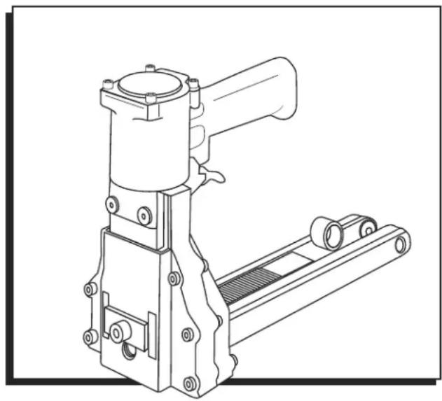
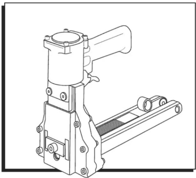
Technical line drawing of a mechanical device with lever and base mount (no text or symbols)STAPLER SPECIFICATIONS
Dimensions: L x W x H 13.5 x 4.53 x 8.66"
Weight (Without Fasteners) 5 lb.
Compressed Air:
Maximum psi: 110 psi
Recommended
Operating Pressure: 80–100 psi
Air Consumption: 2.4 CFM
Staple Specification: S-22482 A58 Stick
Staple Specification: S-22481 C34 Stick
Staple Specification: S-22480 C58 Stick
Staple Capacity: 100 Staples
Noise Levels: 89 dBA
WARNING
Before operating this stapler familiarize yourself with the safety warnings and instructions in this manual. Keep these instructions with the stapler for future reference. If you have any questions, contact Uline at 1-800-295-5510.
SAFETY INSTRUCTIONS
GENERAL SAFETY
- Read the manual and understand all safety instructions before operating the stapler. If you have questions, contact Uline at 1-800-295-5510.
- Never use flammable gases as a power source for the stapler. Only use filtered, compressed air.
- Never use gasoline or other flammable liquids to clean the stapler. Vapors left on the stapler could ignite and cause the stapler to explode.
- Do not exceed 110 psi of air pressure when operating the stapler.
- Disconnect the stapler from the air supply before making adjustments, cleaning or clearing jams and when not in use.
- Do not pull the trigger when carrying or holding the stapler.
- Never carry the stapler by the hose or pull on the hose to move the stapler.
- Always wear protective equipment; i.e., safety glasses, hearing protection and head protection.
- Do not use a check valve or any other fitting which allows air to remain in the stapler.
- Do not place your hand or any other body part in the staple clinching area or adjustment window when connecting or disconnecting the air supply.
- Never point the stapler at yourself or anyone else
- Lubricate the stapler prior to initial operation.
- Disconnect the stapler from the air supply prior to servicing.
- Turn the stapler so that the inlet is facing up and put one drop of high-speed spindle oil, UNOCOL RX22, or 3-in-1 oil, into air inlet. Never use detergent oil or additives.
- Operate the stapler briefly after adding oil.
- Wipe off excessive oil at the exhaust. Excessive oil will damage the O-rings. If inline oiler is used, manual lubrication through the air inlet is not required on a daily basis.
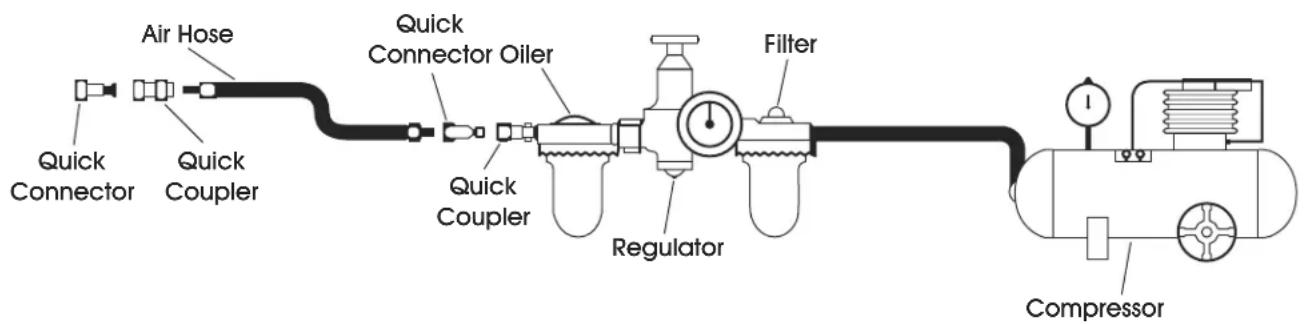
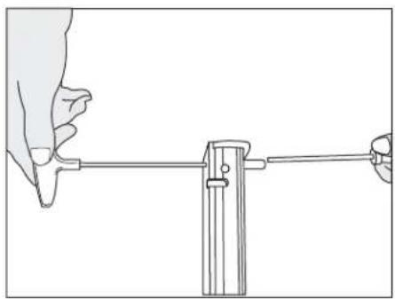
AIR SUPPLY AND CONNECTIONS

NOTE: The following illustration shows the correct mode of connection to the air supply system which will increase the efficiency and life of the stapler.
- Many air stapler users find it convenient to use an inline oiler to provide oil circulation through their stapler. Check oil level in the oiler daily.
- A filter is recommended on your air compressor. Check the filter and drain on a daily basis.
SAFETY INSTRUCTIONS CONTINUED
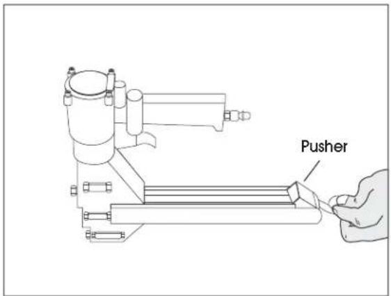
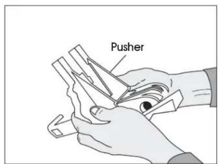
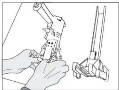
LOADING THE STAPLER
- Disconnect the air supply.
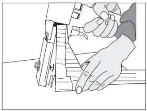
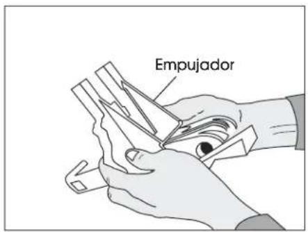
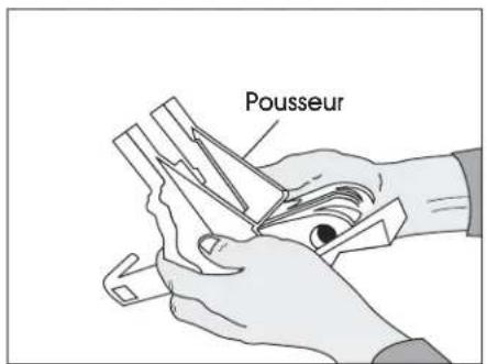
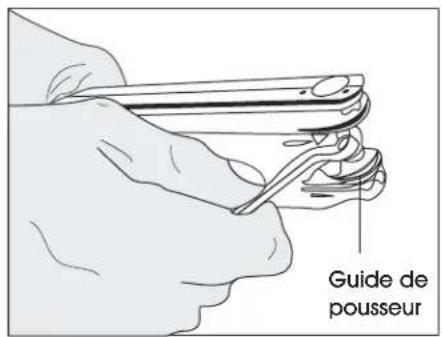
- Pull the pusher back until it stops on pusher pivots. Rotate pusher to position. (See Figure 1)
-
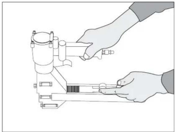
Insert 2 sticks of appropriate staples into the magazine. Let the sticks slide forward to the front of the magazine. (See Figure 2)
-
Pull the pusher back to an upright position and gently let the pusher slide forward against the staples. Do not let the pusher slide forward and strike the staples at high speed as this may deform the staples and damage the stapler.
text_image
PusherFigure 1
natural_image
Illustration of hands operating a mechanical device with a caliper (no text or symbols visible)Figure 2
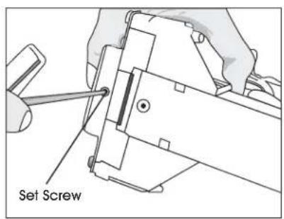
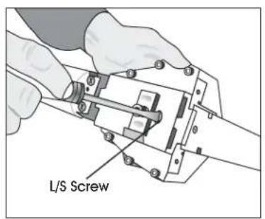
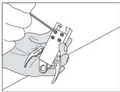
STAPLE LEG LENGTH
- Loosen the set screw on the bottom with a 3 mm Allen wrench. (See Figure 3)
-
Adjust L/S screw with a screwdriver to the desired setting. (See Figure 4)
a. If you are using 3/4" staples set L up.
b. If you are using 5/8" staples set S up. (See Figure 5) -
Tighten the set screw on the bottom.
text_image
Set ScrewFigure 3 Figure 4 Figure 5
text_image
L/S Screw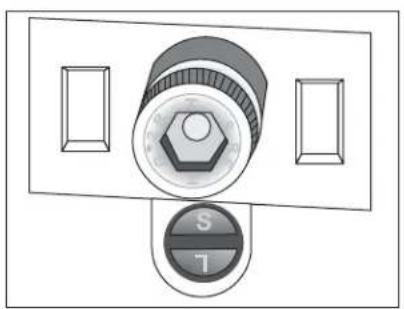
natural_image
Diagram of a control panel with a rotary knob and two rectangular buttons (no text or symbols)SAFETY INSTRUCTIONS CONTINUED
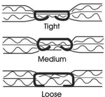
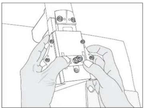
CLINCH ADJUSTMENT
Use 2.5 mm Allen wrench and turn collar through window clockwise to tighten clinch. (See Figure 6)
text_image
Tight Medium LooseFigure 6
natural_image
Illustration of hands operating a mechanical device with no visible text or symbols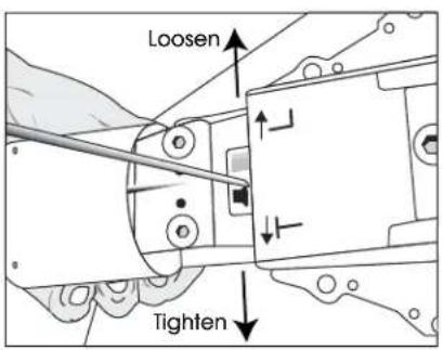
text_image
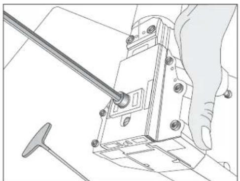
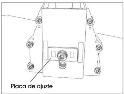
Loosen TightenDEPTH ADJUSTMENT
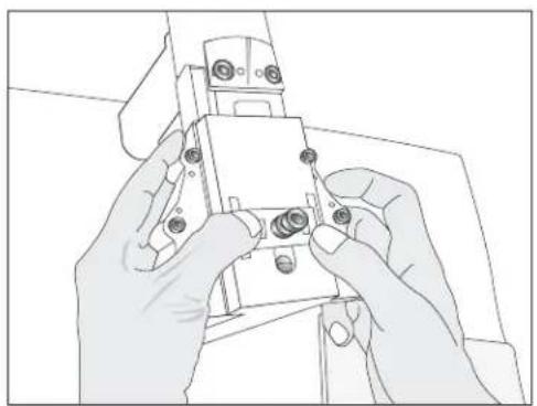
- Loosen front screw with a 6 mm Allen wrench. (See Figure 7)
-
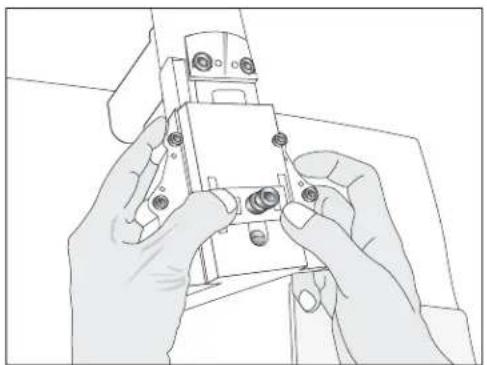
Push the body up and adjust to the desired depth. (See Figure 8)
-
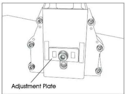
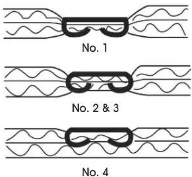
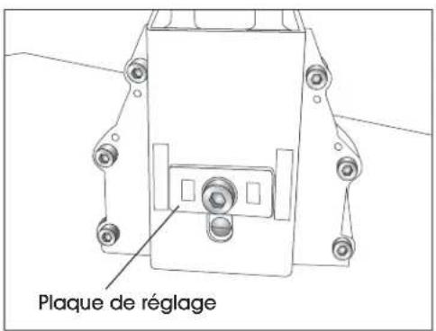
When the top edge of the adjustment plate is at its highest setting the teeth are at their shallowest penetration. (See Figure 9)
- If set at No. 1 the teeth are at their deepest penetration. (See Figure 10)
natural_image
Technical line drawing of a mechanical assembly with a hand operating a tool (no text or symbols)Figure 7
natural_image
Line drawing of hands assembling a small electronic component (no text or symbols visible)Figure 8
text_image
Adjustment PlateFigure 9
text_image
No. 1 No. 2 & 3 No. 4Figure 10
OPERATING INSTRUCTIONS
WARNING
- Protect your eyes and ears.
a. Wear safety glasses with side shields
b. Wear hearing protection.
c. Ensure that anyone in the vicinity wears safety protection.
-
To prevent accidental injuries, never place a hand or any other body part in the staple clinching area or adjustment window.
-
Never point the stapler towards you or anyone else.
- Always handle the stapler with care. Never pull the trigger unless stapler is ready for operation.
-
Check and replace any damaged or worn components on the stapler.
-
Add a few drops of oil into the air inlet.
- Install a quick connect fitting to the stapler.
- Regulate the air pressure to attain 80–100psi.
-
Insert the staples into the stapler following the loading instructions.
-
Reconnect the air hose to the stapler.
- Grasp the handle with one hand on box in line with the desired staple location. There is a small projection on either side of the magazine seat as an aid in locating the position of the staple.
- The strongest closure requires staples close to the ends of the box.
WARNING
Never use gasoline or other flammable liquids to clean the stapler. Vapors in the stapler could be ignited by a spark and cause the stapler to explode.
CLEANING THE STAPLER
- Disconnect the air supply from the stapler
- Remove tar buildup with non-corrosive cleaner.

CAUTION! Do not allow solvent to get into the cylinder or damage may occur.
- Dry the stapler completely before use.
OPERATING INSTRUCTIONS CONTINUED
CLEARING A JAM
- Disconnect air supply.
- Pull pusher back and rotate to a locked position. (See Figure 11)
natural_image
Technical line drawing of a mechanical assembly (no text or symbols)Figure 11
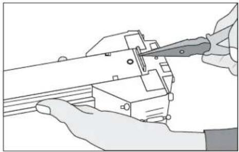
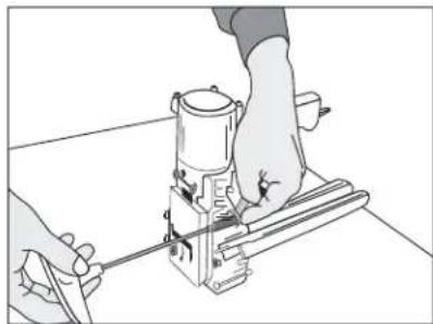
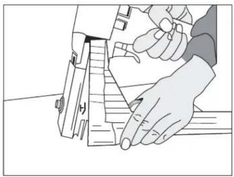
- Insert needle nose pliers or screwdriver to clear jam. (See Figure 12)
- Slowly release pusher back to position.
natural_image
Illustration of hands using a tool to adjust or install electronic components (no text or symbols visible)Figure 12
WARNING
Stop using the stapler immediately if any of the following problems occur. Serious personal injury could occur. Any repairs or replacements must be done by a qualified person or authorized service center only.
TROUBLESHOOTING
| PROBLEM CAUSE REMEDY | ||
| Air leak from trigger O-ring on valve or on tube is damaged. Replace O-ring. | ||
| Air leak from exhaust port O-ring on valve or on tube is damaged.O-ring on piston is damaged. | Replace O-ring. | |
| Air leak from cylinder Piston rod port O-ring is damaged. Replace O-ring | ||
| Slow and short travel cycling | Check for loose screw or wear of parts. | 1. Position eccentric pin and tighten screw.2. Recheck for maximum efficiency.a. Adjust pin slightly upward if due to short travel.b. Adjust pin slightly downward if due to slow cycling. |
| Excessive jams | 1. Slow and short travel cycle.2. Teeth screws are loose.3. Wrong staple size.4. Insufficient lubrication. | 1. Adjust as noted above.2. Tighten screws.3. Check staples.4. Clean and lubricate. |
| Uneven clinch | Wrong staple size. | Check for proper leg length adjustment and clincher size. |
| Unclinched staple | 1. Teeth are loose or broken.2. Slow and short travel cycle. | 1. Check and replace teeth as needed.2. Adjust as noted above. |
OPERATING INSTRUCTIONS CONTINUED
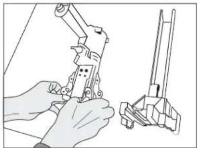
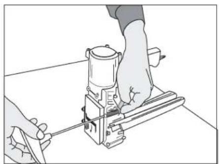
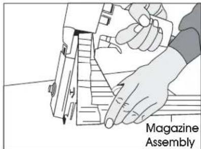
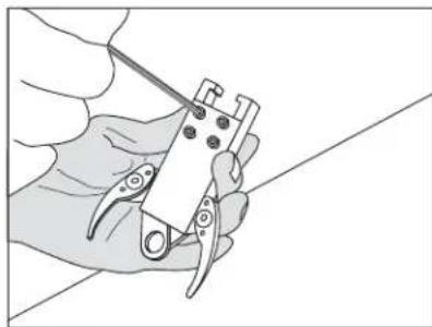
TEETH REPLACEMENT
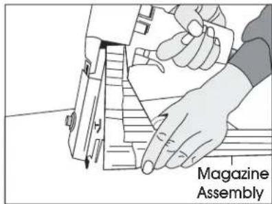
- Loosen screws and nut with an 8 mm wrench and 4 mm Allen wrench. (See Figure 13)
-
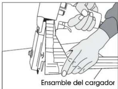
Remove the magazine assembly. (See Figure 14)
-
Loosen screws with 3 mm Allen wrench. (See Figure 15)
-
Change teeth one at a time to prevent reverse teeth.
natural_image
Illustration of hands operating a mechanical device with a tool, no text or symbols presentFigure 13 Figure 14
natural_image
Illustration of a hand using a tool to cut or mark a piece of paper (no text or symbols visible)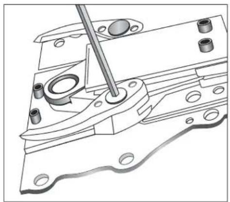
natural_image
Technical line drawing of a mechanical assembly with a tool inserted, showing no text or symbolsFigure 15
OPERATING INSTRUCTIONS CONTINUED
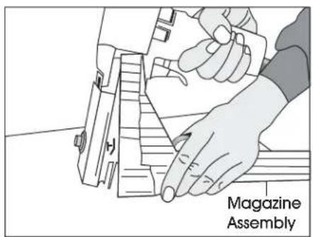
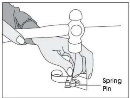
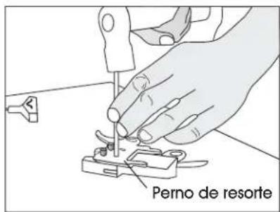
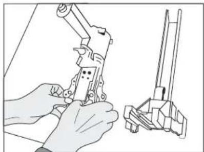
DRIVER REPLACEMENT
- Disconnect the air supply.
- Loosen screw and nut with a 8 mm spanner wrench and a 4 mm Allen wrench. (See Figure 16)
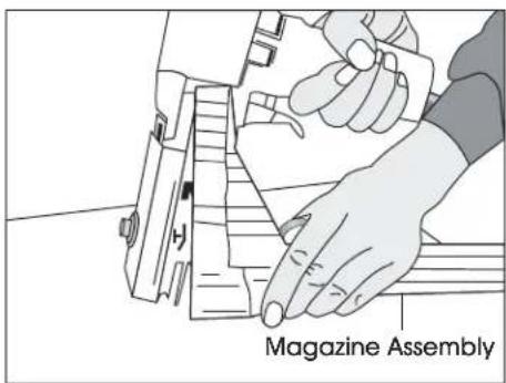
- Remove the magazine assembly. (See Figure 17)
-
Loosen the set screw with a 3 mm Allen wrench to unlock the adjusting rod.
-
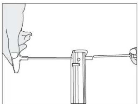
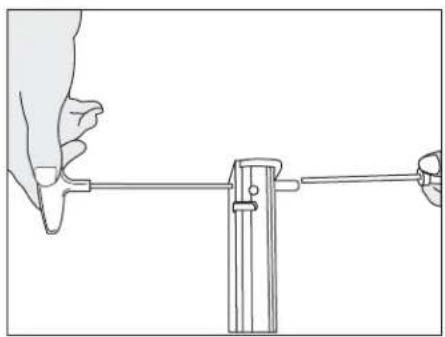
Slide the linkage mechanism and adjusting rod simultaneously from the collar. (See Figure 18)
- Loosen the screws with a 3 mm Allen wrench. (See Figure 19)
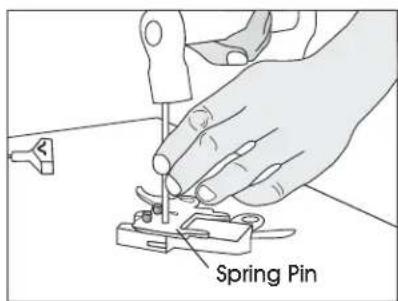
- Take off the spring pin with a hammer and 6 mm straight rod. (See Figure 20)
natural_image
Line drawing of hands operating a mechanical device with a cylindrical component (no text or symbols)Figure 16
text_image
Magazine AssemblyFigure 17
natural_image
Illustration of hands using a mechanical tool to adjust or install a component (no text or symbols visible)Figure 18

natural_image
Illustration of a hand using a power tool to cut or adjust a small component (no text or symbols visible)Figure 19

text_image
Spring PinFigure 20
OPERATING INSTRUCTIONS CONTINUED
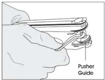
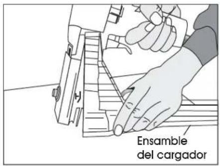
PUSHER SPRING REPLACEMENT
- Loosen the screws and nut with a 8 mm spanner wrench and a 4 mm Allen wrench. (See Figure 21)
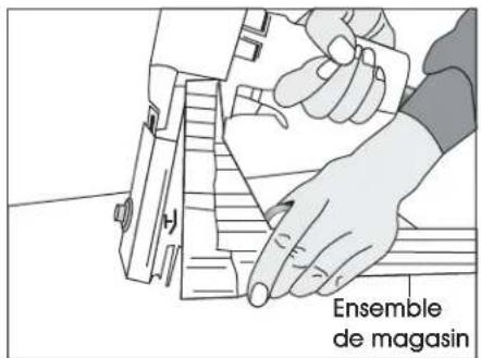
- Remove the magazine assembly. (See Figure 22)
- Pull the pusher back until it stops on the rod, then rotate the pusher to position. (See Figure 23)
-
Push the magazine seat back and remove it from the magazine.
-
Loosen the screw and nut with a 2.5 mm Allen wrench and 7 mm socket wrench. (See Figure 24)
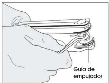
- Loosen the rod with a 6 mm offset wrench and remove the pusher guides. Remove the pusher. (See Figure 25)
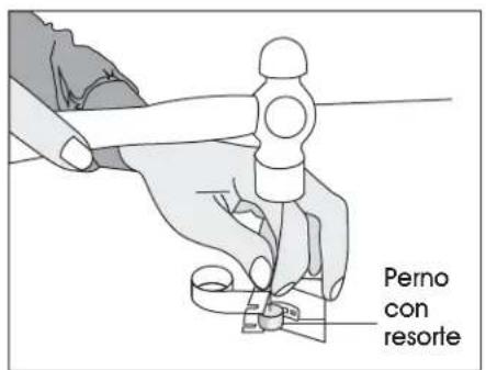
- Remove the spring pin with a hammer and 4 mm straight rod. (See Figure 26)
natural_image
Line drawing of hands using a tool to adjust or install a mechanical component (no text or symbols visible)Figure 21
text_image
Magazine AssemblyFigure 22
text_image
PusherFigure 23
natural_image
Line drawing of a hand holding a tool with a vertical rod, connected to a vertical support (no text or symbols)Figure 24
text_image
Pusher GuideFigure 25
text_image
Spring PinFigure 26
OPERATING INSTRUCTIONS CONTINUED
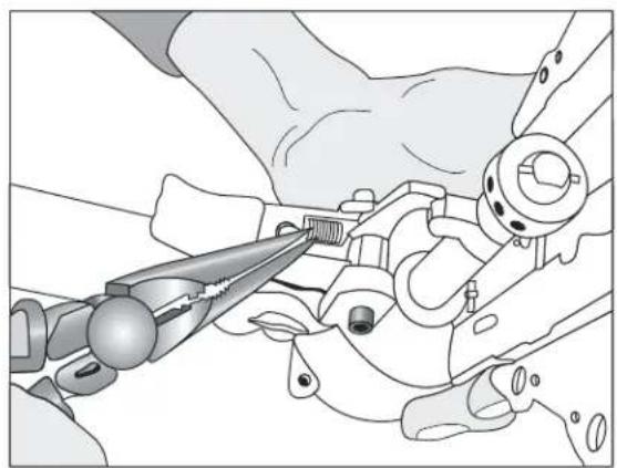
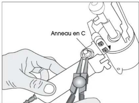
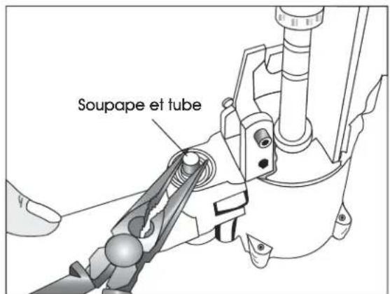
VALVE AND TUBE O-RING REPLACEMENT
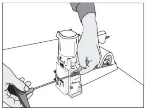
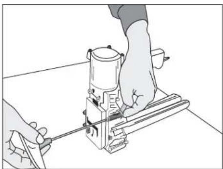
- Loosen screws with a flat screwdriver. (See Figure 27)
-
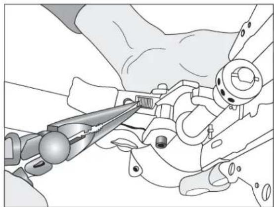
Remove spring with needle nose pliers. (See Figure 28)
-
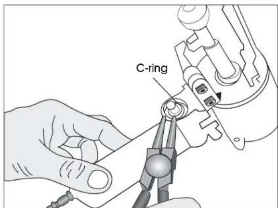
Remove C-ring with C-ring pliers. (See Figure 29)
-
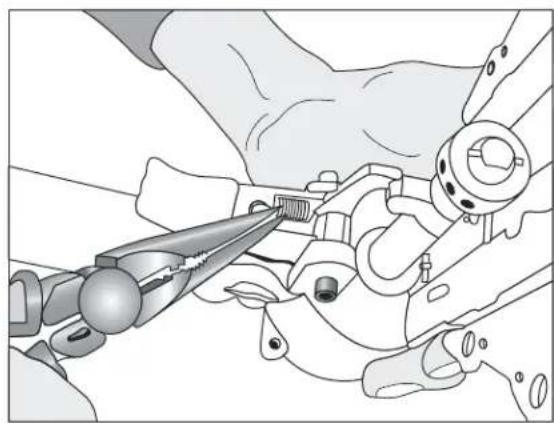
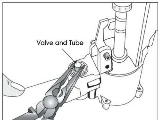
Remove valve and tube with needle nose pliers. (See Figure 30)
natural_image
Illustration of hands using a tool to adjust or install a mechanical component (no text or symbols visible)Figure 27
natural_image
Illustration of a hand using pliers to adjust mechanical components (no text or symbols visible)Figure 28
text_image
C-ringFigure 29
text_image
Valve and TubeFigure 30
OPERATING INSTRUCTIONS CONTINUED
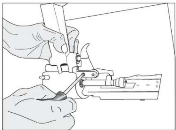
PISTON REPLACEMENT
- Remove screws and nut with 8 mm spanner wrench and 4 mm Allen wrench. (See Figure 31)
- Remove magazine assembly. (See Figure 32)
- Loosen set screw with a 3 mm Allen wrench to unlock the adjusting rod.
- Slide linkage mechanism and adjusting rod simultaneously from collar.
-
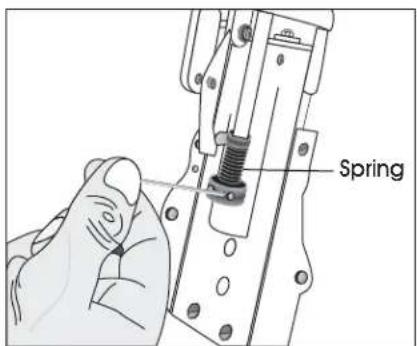
Loosen collar with a 3 mm Allen wrench to remove the spring. (See Figure 33)
-
Loosen screw with a 3 mm Allen wrench and remove the block through the window.
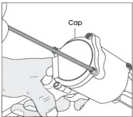
- Loosen screws with a 3 mm Allen wrench and remove the cap. (See Figure 34)
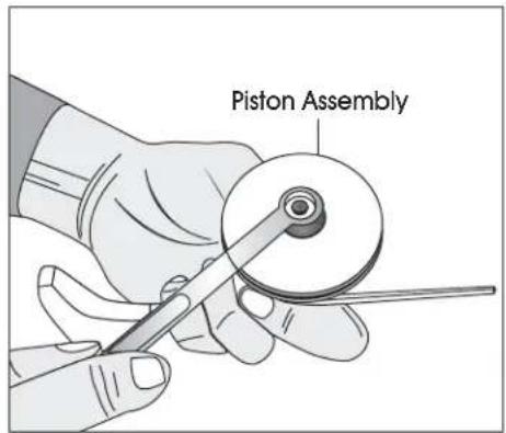
- Remove the piston assembly with a 10 mm spanner wrench. (See Figure 35)
- Remove piston and replace.
natural_image
Line drawing of hands operating a mechanical device on a workbench (no text or symbols)Figure 31
text_image
Magazine AssemblyFigure 32
text_image
SpringFigure 33
text_image
CapFigure 34
text_image
Piston AssemblyFigure 35
natural_image
Technical line drawing of a mechanical device with lever and base mount (no text or symbols)(13.5 × 4.53 × 8.66")
Peso (sin cinchos) 2.3 kg (5 lbs.)
Aire comprimido:
PSI Máximo: 110 PSI
Presión operativa
Recomendada: 80–100 PSI
Consumo de aire: 0.07 m³/min (2.4 pie³/min)
natural_image
Illustration of hands operating a mechanical device with a tool handle (no text or symbols visible)Diagrama 2
LARGO DE PATA DE LA GRAPA
natural_image
Diagram of a rotary switch with labeled buttons (S and T) and control panel (no text or symbols beyond labels)natural_image
Illustration of hands operating a mechanical device with no visible text or symbols
text_image
Aflojar Apretarnatural_image
Technical line drawing of a mechanical assembly with a tool and bracket (no text or symbols)Diagrama 7
natural_image
Line drawing of hands assembling a small electronic component (no text or symbols visible)Diagrama 8
text_image
Placa de ajusteDiagrama 9
No. 1
No. 2 & 3
No. 4
Diagrama 10
natural_image
Technical line drawing of a mechanical assembly (no text or symbols)Diagrama 11
natural_image
Line drawing of hands using a tool to adjust or install electronic components (no text or symbols visible)Diagrama 12
ADVERTENCIA
natural_image
Illustration of hands using a tool on a mechanical device (no text or symbols visible)natural_image
Illustration of a hand using a tool to cut or mark a piece of paper (no text or symbols visible)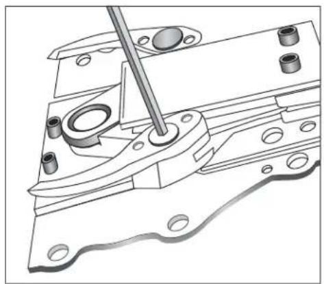
natural_image
Technical line drawing of a mechanical assembly with a tool inserted, showing no text or symbolsDiagrama 15
natural_image
Line drawing of hands operating a mechanical presser or clamp device (no text or symbols present)Diagrama 16
text_image
Ensamble del cargadorDiagrama 17
natural_image
Illustration of hands operating a mechanical device with a separate view showing a tool (no text or symbols present)Diagrama 18
natural_image
Illustration of a hand using a power tool to cut a component (no text or symbols visible)Diagrama 19
text_image
Perno de resorteDiagrama 20
natural_image
Line drawing of hands using a mechanical tool to adjust or install a component (no text or symbols visible)Diagrama 21
text_image
Ensamble del cargadorDiagrama 22
text_image
EmpujadorDiagrama 23
natural_image
Line drawing of a hand holding a tool with a vertical rod, connected to a vertical support (no text or symbols)Diagrama 24
text_image
Guía de empujadorDiagrama 25
text_image
Perno con resorteDiagrama 26
natural_image
Illustration of hands using a tool to adjust or install a mechanical component (no text or symbols visible)Diagrama 27
natural_image
Illustration of a hand using a pliers to adjust mechanical components (no text or symbols visible)Diagrama 28
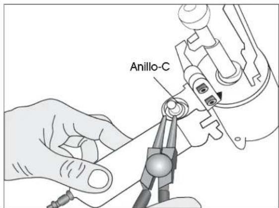
text_image
Anillo-CDiagrama 29

natural_image
Line drawing of hands operating a mechanical device on a workbench (no text or symbols)Diagrama 31
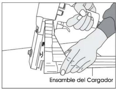
text_image
Ensamble del CargadorDiagrama 32
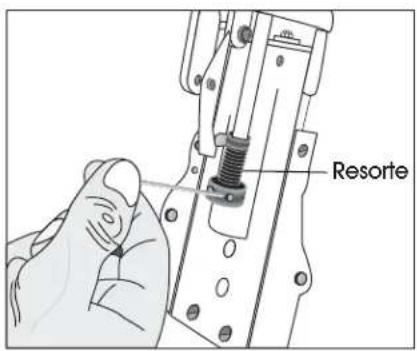
text_image
ResorteDiagrama 33
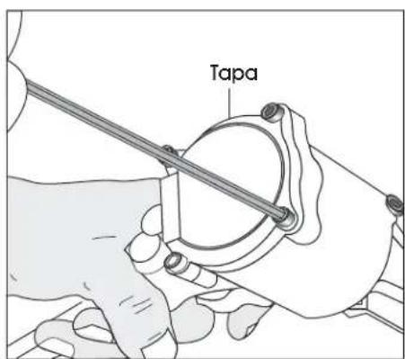
text_image
TapaDiagrama 34
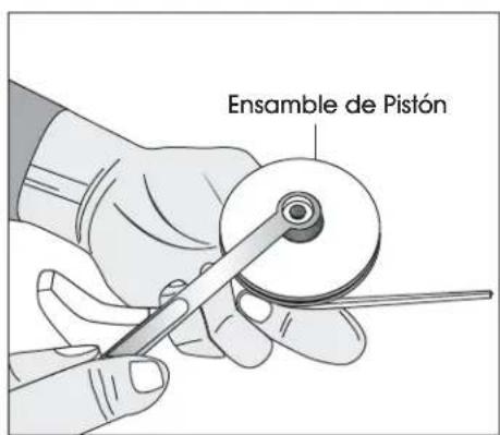
text_image
Ensamble de PistónDiagrama 35
natural_image
Technical line drawing of a mechanical device with lever and base mount (no text or symbols)SPÉCIFICATIONS DE L'AGRAFEUSE
Dimensions : long. x larg. x haut. 34 x 11,5 x 22 cm
(13,5 x 4,53 x 8,66 po)
Poids (sans agrafes) 2,3 kg (5 lb)
Air comprimé :
Pression maximum : 6,9 bars (110 lb/po ^2 )
Pression
natural_image
Illustration of hands operating a mechanical device with a caliper (no text or symbols visible)Figure 2
LONGUEUR DE PATTE D'AGRAFE
Figure 3 Figure 4 Figure 5
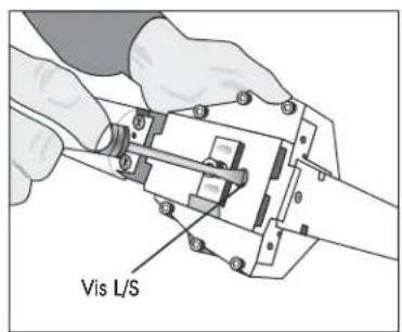
text_image
Vis L/S
natural_image
Diagram of a rotary switch with labeled buttons (S and T) and two side panels, no text or symbols present.natural_image
Illustration of hands operating a mechanical device with no visible text or symbols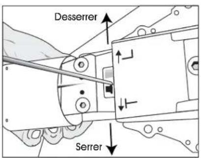
text_image
Desserrer Serrernatural_image
Technical line drawing of a hand operating a mechanical device with a tool (no text or symbols visible)Figure 7
natural_image
Line drawing of hands assembling a small electronic component (no text or symbols visible)Figure 8
natural_image
Technical line drawing of a mechanical assembly (no text or symbols)Figure 11 Figure 12

natural_image
Illustration of hands using a tool to adjust or install electronic components (no text or symbols visible)AVERTISSEMENT
REPLACEMENT DE DENTS
natural_image
Illustration of hands operating a mechanical device with a tool, no text or symbols presentFigure 13 Figure 14
natural_image
Illustration of a hand using a tool to cut or mark a piece of paper (no text or symbols visible)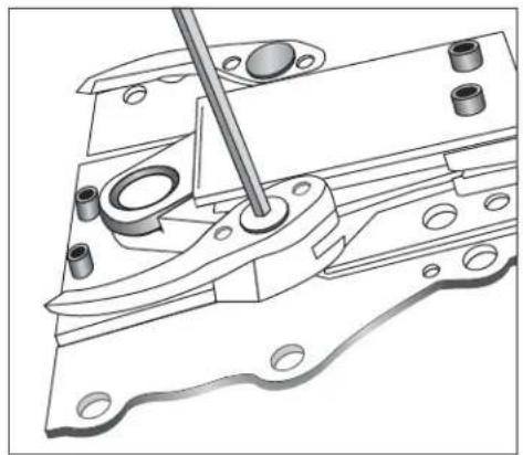
natural_image
Technical line drawing of a mechanical assembly with a tool inserted, showing no text or symbolsFigure 15
INSTRUCTIONS D'UTILISATION SUITE
REEMPLACEMENT DE LA PLAQUE DE POUSSÉE
natural_image
Line drawing of hands operating a mechanical device with a tool (no text or symbols visible)Figure 16
text_image
Magazine AssemblyFigure 17
natural_image
Illustration of hands operating a mechanical device with a separate view of a mechanical component (no text or symbols present)Figure 18
natural_image
Illustration of a hand using a power tool to cut a component (no text or symbols visible)Figure 19
text_image
Spring PinFigure 20
INSTRUCTIONS D'UTILISATION SUITE
REPLACEMENT DU RESSORT DE POUSSEUR
natural_image
Line drawing of hands using a tool to adjust or install a mechanical component (no text or symbols visible)Figure 21
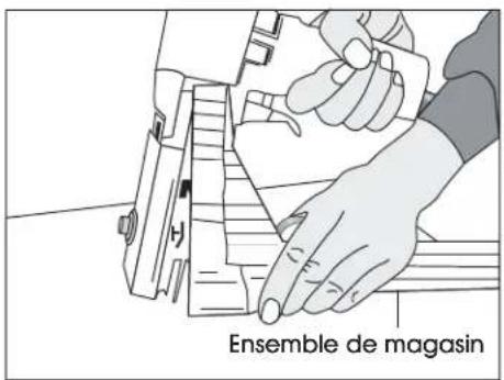
text_image
Ensemble de magasinFigure 22
text_image
PousseurFigure 23
natural_image
Line drawing of a hand holding a tool with a vertical rod, connected to a horizontal line (no text or symbols)Figure 24
text_image
Cheville ressortFigure 26
INSTRUCTIONS D'UTILISATION SUITE
REMPLACEMENT DU JOINT TORIQUE DE SOUPAPE ET TUBE
natural_image
Illustration of hands using a tool to adjust or install a mechanical component (no text or symbols visible)Figure 27
natural_image
Illustration of hands using pliers to adjust mechanical components (no text or symbols visible)Figure 28
text_image
Anneau en CFigure 29
text_image
Soupape et tubeFigure 30
INSTRUCTIONS D'UTILISATION SUITE
REPLACEMENT DU PISTON
natural_image
Line drawing of hands operating a mechanical device on a workbench (no text or symbols)Figure 31
text_image
Ensemble de magasinFigure 32
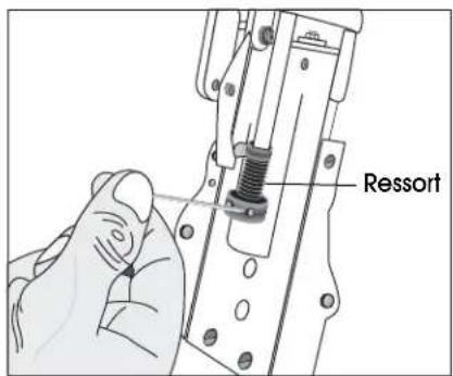
text_image
RessortFigure 33
text_image
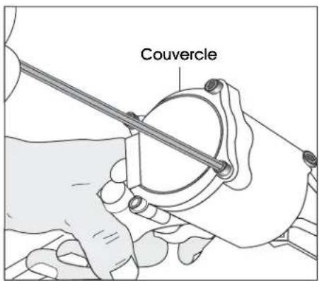
CouvercleFigure 34
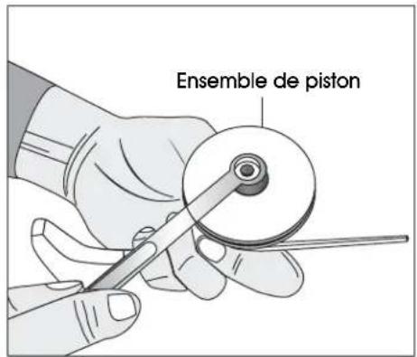
text_image
Ensemble de pistonFigure 35


