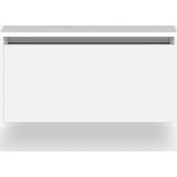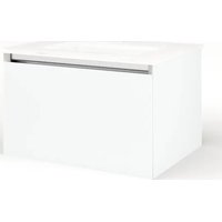
VM24H2D18P26N - Vanity unit Robern - Free user manual and instructions
Find the device manual for free VM24H2D18P26N Robern in PDF.


| Product type | Vanity cabinet |
| Brand | Robern |
| Model | VM24H2D18P26N |
| Dimensions (W x H x D) | 609.6 mm x 381 mm x 533.4 mm |
| Materials | Glass and aluminum |
| Electrical supply (optional) | 120 VAC, 20 A, protected GFCI circuit |
| Lighting (optional) | Integrated night light without switch |
| Electrical outlet (optional) | With recommended GFCI |
| Installation options | Single, paired, stacked, alcove, corner |
| Drawer type | Full drawer with divider |
| Mounting kit contents | Structural bolts (5/16" x 2-1/2"), screws, divider clips, washers |
| Number of manual pages | 40 pages |
| Recommended maintenance | 50/50 isopropyl alcohol/water solution, soft cloth |
| Prohibited cleaners | Abrasives, ammonia, vinegar |
| Warranty | Limited, 1 year |
| Repairability | Spare parts available on request |
| Installation required | By a professional, comply with local codes |
Frequently Asked Questions - VM24H2D18P26N Robern
User questions about VM24H2D18P26N Robern
0 question about this device. Answer the ones you know or ask your own.
Ask a new question about this device
Download the instructions for your Vanity unit in PDF format for free! Find your manual VM24H2D18P26N - Robern and take your electronic device back in hand. On this page are published all the documents necessary for the use of your device. VM24H2D18P26N by Robern.
USER MANUAL VM24H2D18P26N Robern
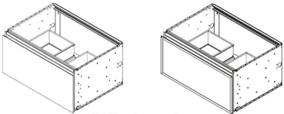
Important safety instructions - Save these instructions
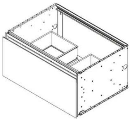
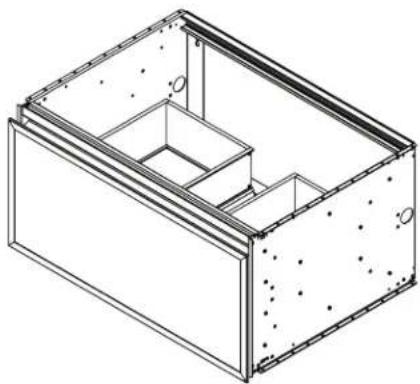
Side Kits sold separately
CONTENTS
Installation Instructions - 1
Model Numbers - 2
Parts and Optional Accessories - 3 & 4
Dimensions - 5
Blocking Dimensions - 6
Electric Option Rough-in - 7
Frame Installation - 8 & 9
Stacking Kit - 10
Optional Ganging Kit - 11
Alcove and Corner Installations - 12
Optional Side kit / Optional Selectable Night Light - 13
Accessory Installation - 14
Optional Slim Printer Insert - 15
Drawer Installation - 16, 17, & 18
Use and Maintenance / Warranty - 19
Français / Espanol - 20
INSTALLATION INSTRUCTIONS
This instruction manual contains information on how to install the 15" high Cartesian Vanity, and Profiles Vanity. This series comes in several sizes and variations. Electrical option(s) may be provided with your vanity(s). The vanity series is modular and can be mounted individually, ganged or stacked together.
This vanity series needs special site preparation. Do not install vanities until all framing, plumbing and electrical option rough-ins have been completed and wall surface has been finished. We recommend using the services of a professional installer. Observe all local building codes.
Save these instructions for future use and reference. An improper installation voids the warranty. Installed vanities cannot be returned.
If you experience any problems with your vanities, contact your dealer or Robern directly.
Limited Warranty — One Year Term
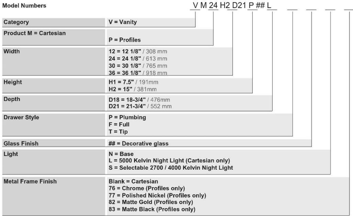
MODEL NUMBERS
Use the chart Below to learn how to build a Cartesian and Profiles Model number. This chart references the model number for a 24" W x 15" H x 21" D vanity with plumbing drawer and night light. Consult the Robern Price Book for a complete list of model numbers.
PARTS
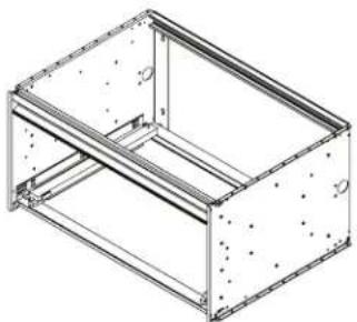
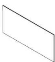
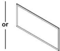
(1) 12", 24", 30", or 36" frame - 30" shown here (1) Drawer front
24", 30", or 36" Plumbing Driver 12", 24", 30", or 36" Full Driver
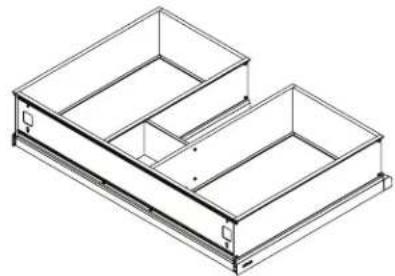

[202-1179] (1) Glass Center Bin
[225-1039] = 24" [225-1040] = 30" [225-1041] = 36"
Divider Set Plumbing Drawer
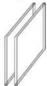
Divider Glass DivideqerClip


[211-1098]
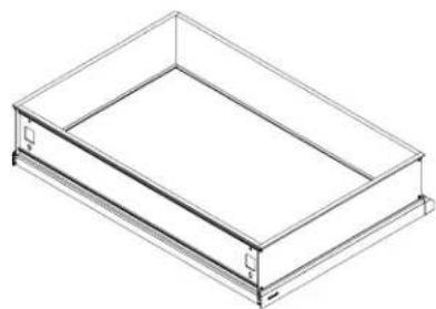
(4) Divider Clip Shoe
[225-1042]
Divider Set Full Drawer
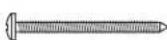
[SS674]
(5) #10 x 2" Screw
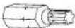
[203-1270]
T-30 Driver

[216-1145]
Stacking Hardware Bag
[203-1317]
(4) 10-32 Nut

[SS268]
(4) 10-32 Screw

[203-1390]
(4) #10 Washer

[216-1074]
Drawer front Hardware Bag
[203-1219]
(4) #8-32 x 1/2" Screw

[203-1198]
(4) Washer
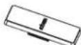
[211-1095]
(2) Screw cover
OPTIONAL ACCESSORIES
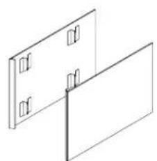
[VM(1,2)SKH2D(18,21)##] Side Kit
Side Kit
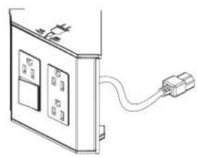
[VAELECTRIC(18, 21)]
Electric Outlet
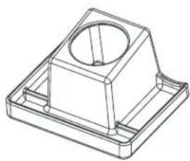
[VAHAIRORG]
Hair Organizer
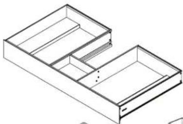
24" = [VADRAWER24P]
-30" = [VADRAWER30PT]
36^ = [VADRAWER36P]
SlimDrawer Insert - PlumbingDrawer With 5 Glass Bins
[202-1356]
(1) Glass Center Bin
[202-1124]
(2) Medium Glass Bin
[202-1123]
(2) Large Glass Bin
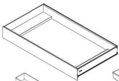
12"=[VADRAWER12X]
24"=[VADRAWER24X]
30"=[VADRAWER30X1
36'' = [VADRAWER 36X]
SlimDrawer Insert - FullDrawer With 4 Glass Bins
[202-1124]
(2) Medium Glass Bin
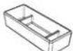
[202-1123]
(2) Large Glass Bin

[GLASSBIN6.38]
Glass Center Bin

[GLASSBIN5.25]
Medium Glass Bin
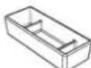
[GLASSBIN8.5]
Large Glass Bin

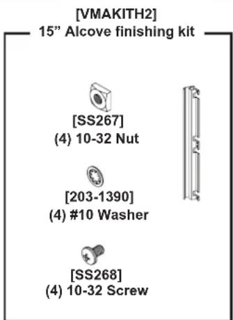
[VMAKITH2]
15" Alcove finishing kit
[SS267]
(4) 10-32 Nut

[203-1390]
(4) #10 Washer

[SS268]
(4) 10-32 Screw


(1) 15^ Filler / Bumper
[VMGKITH2]
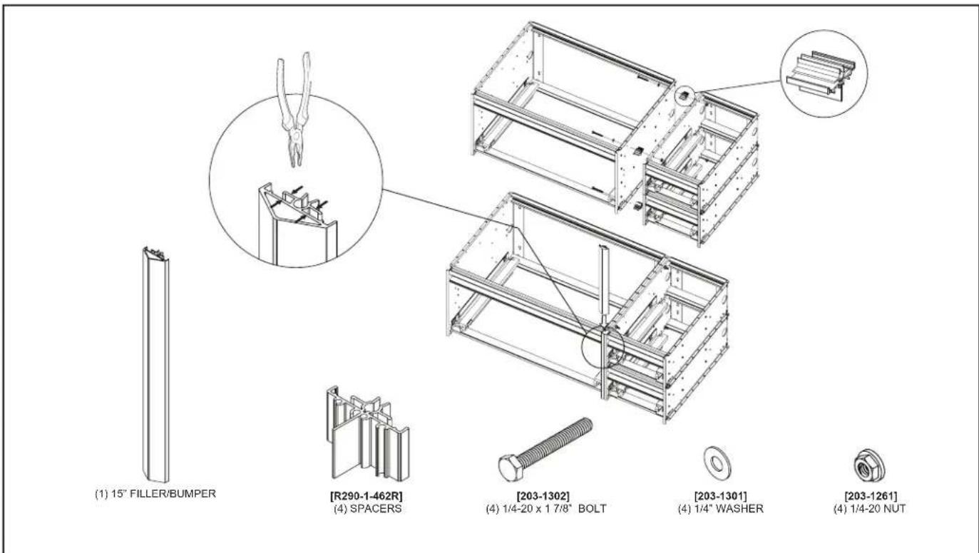
15" Ganging kit
[203-1302]
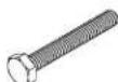
(4) 1 / 4 - 20 × 17 / 8 Bolt

[203-1301]
(4) 1 / 4'' Washer
[R290-1-462R]
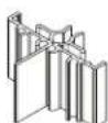
(4) Spacers

[203-1261]
(4) 1/4-20 Nut
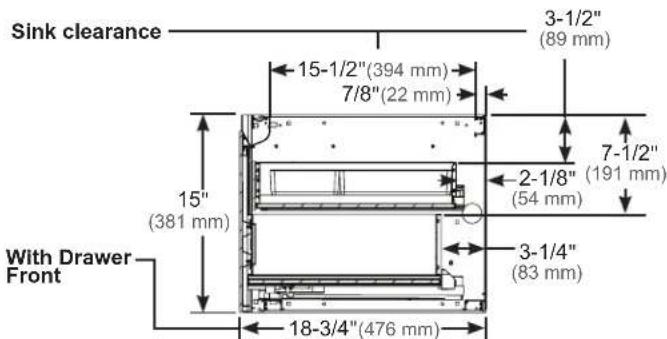
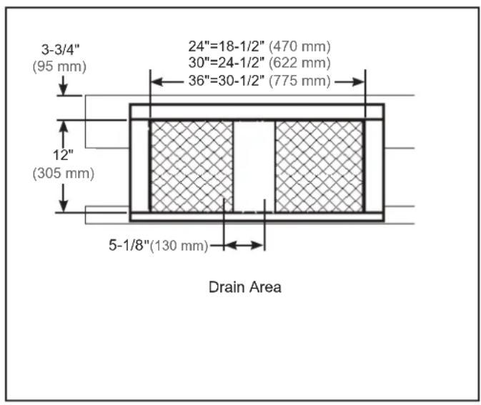
DIMENSIONS
D21 D18
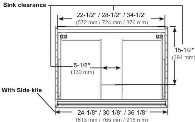
D21 Top View - Section with Plumbing Driver
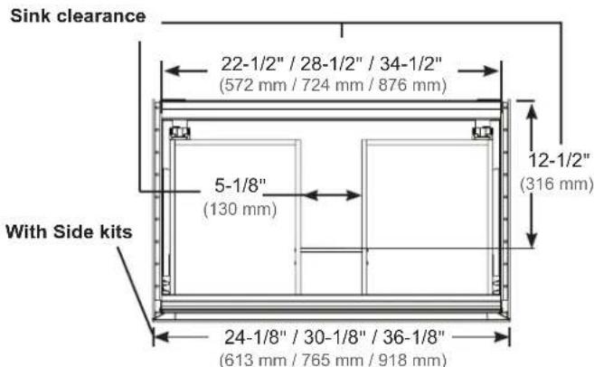
D18 Top View - Section with Plumbing Driver
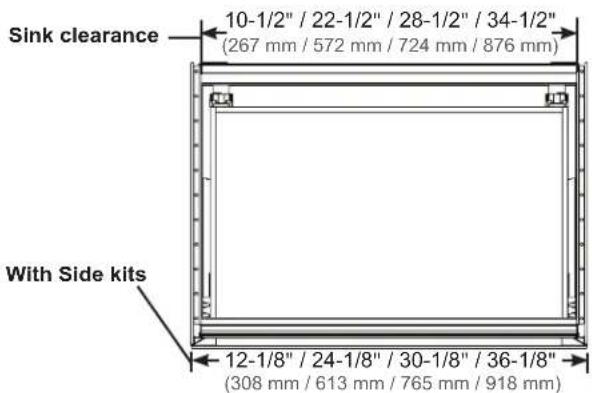
D21 Top View - Section with Full Printer
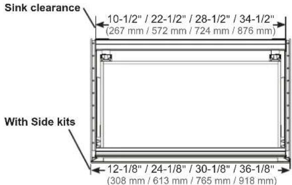
D18 Top View - Section with Full Printer
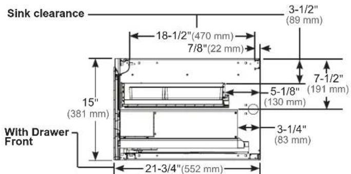
D21 Cross-section with VADRAWER D18 Cross-section with VADRAWER
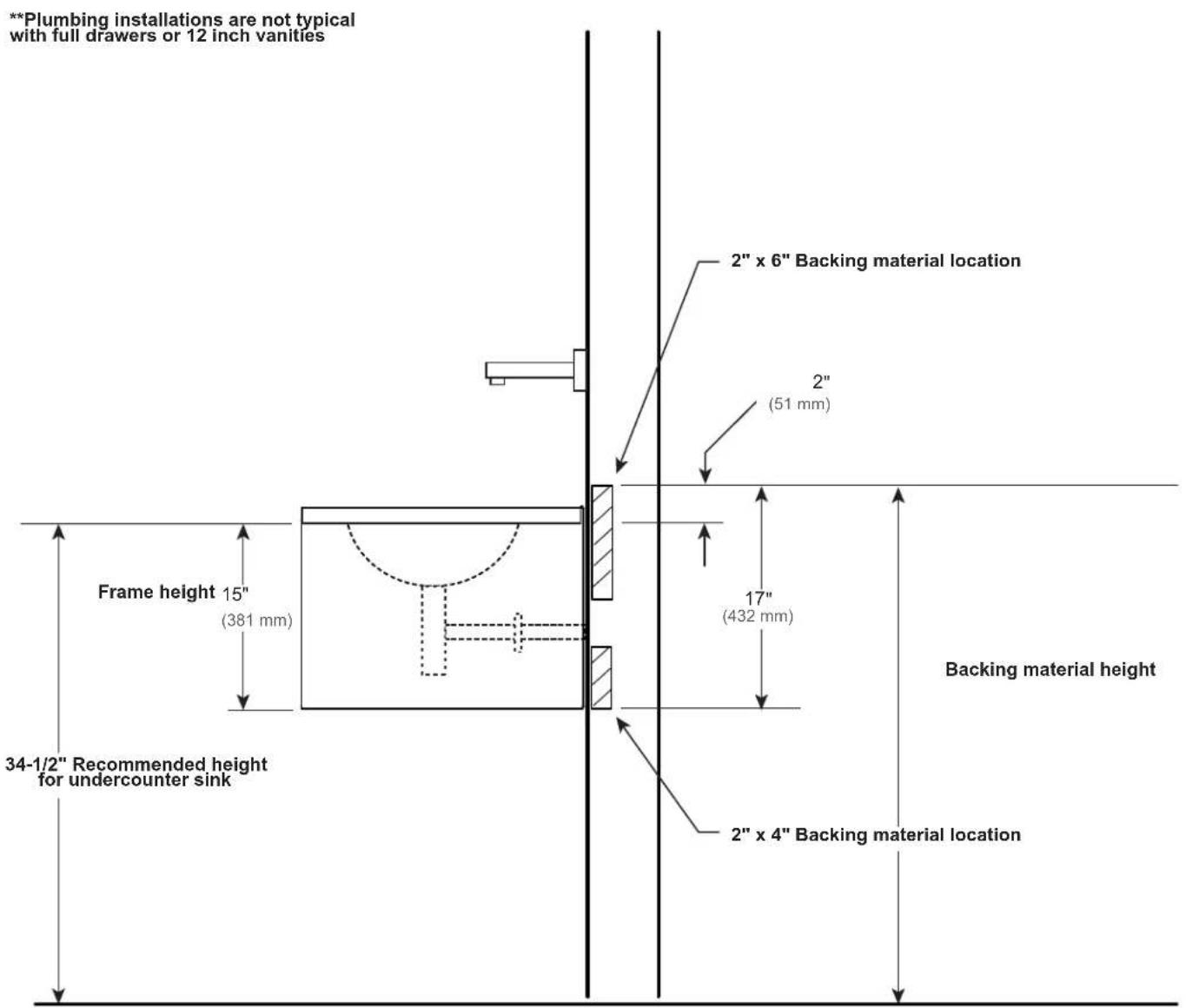
BLOCKING DIMENSIONS
Side view showing blocking location in wall
ELECTRIC OPTION ROUGH-IN
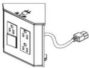
There are two types of electrical options available for vanities. The first is a night light option ordered with the vanity and requires electrical outlets. The second is an electrical outlet option. Both of these options can be plugged into the same outlet.
The outlet must be wired to a 120vac 20 amp GFCI circuit. We do not recommend using a GFCI outlet because resetting it under the vanity will be inconvenient.
The night light has no switch. It is recommended that you switch the outlet to operate the night light. Locate the switch near the doorway to the bathroom.
All applicable electrical codes in your area must be followed.
Outlet can be installed to the left or right of center depending on which side the optional Electrical Outlet Drawer will be located.
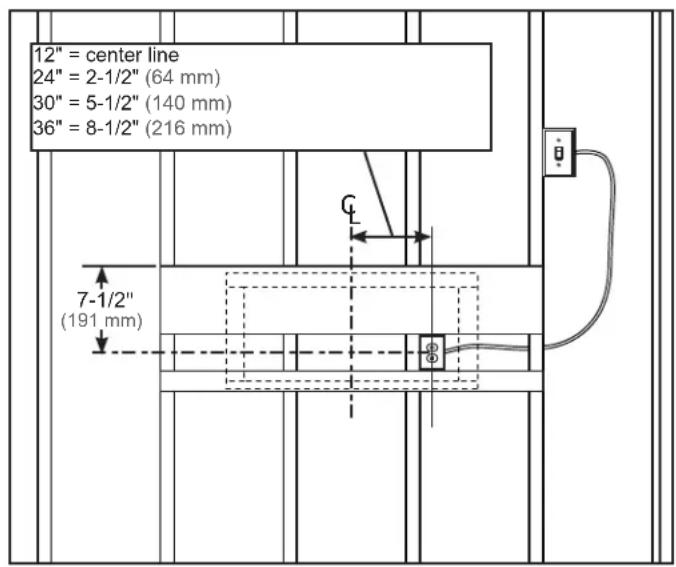
FRAME INSTALLATION
The drawer fronts are packed separately. Do not unpack them until the room is safe from hazards. If you are ganging and / or stacking vanities see pages 10 & 11.
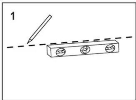
- Mark the height for the vanity frame install on the finished wall (Fig. 1).
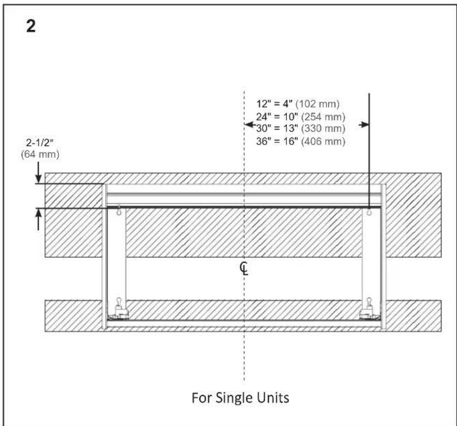
- Install two of the #10 x 2" (SS674) at the locations shown in Fig. 2. Do not install tight to the wall, leave 1/8" behind the head.
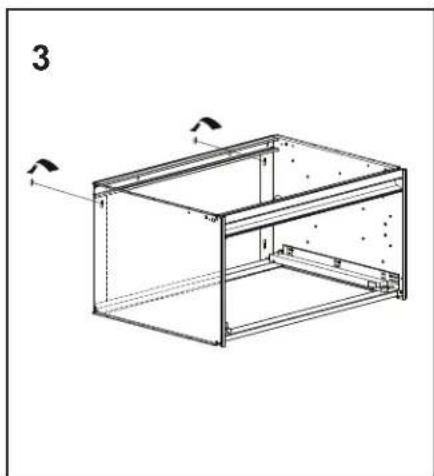
- Place the vanity frame on the screws using the top left and right keyholes (Fig. 3). The keyhole on the left allows for up and down adjustment.
WARNING: THESE SCREWS ARE NOT THE FINAL SUPPORT FOR THE VANITY! SEE PAGE 9 FOR FINAL BOLT UP.
FRAME INSTALLATION
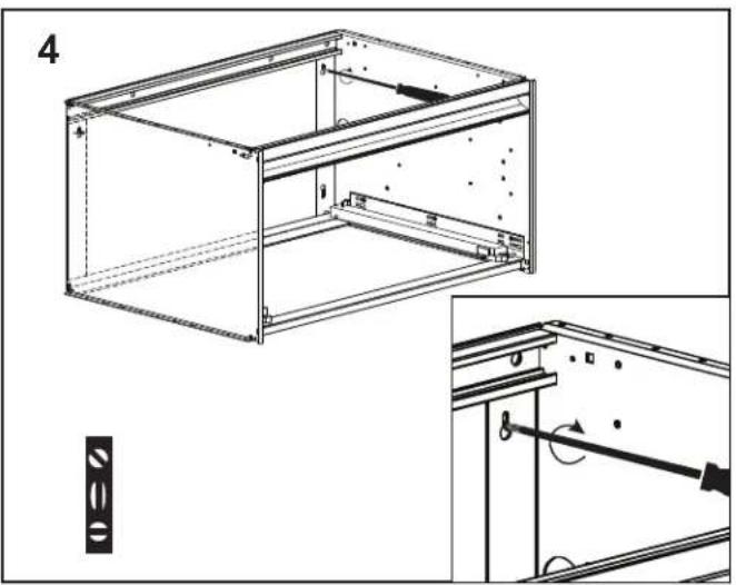
- Level the frame and tighten to the wall as shown on page 8 and here in Fig. 4. The left keyhole is elongated to allow for up and down adjustment.
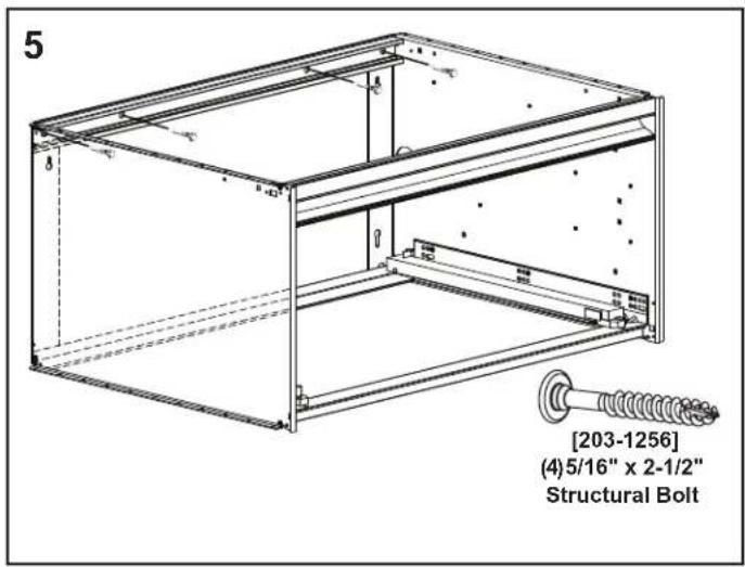
- Install the four Structural Screws (203-1256) into the four top frame holes. Figure 5. A T-30 Torx Bit is provided. If the wall is bowed, shim where required.
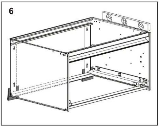
- If required, shim the bottom at the frame/side intersection (Fig. 6).
- Install two # 10× 2^ (SS674) through the narrow slot of the keyhole on the flange (Fig. 7).

STACKINGKIT
If you are not Stacking and/or Ganging Cartesian or Profiles, you may skip this step and continue to assembling the glass drawer front on page 15.
If you purchased the optional side kits, continue to page 13. For the optional Alcove Kit continue to page 12.
Assemble frames on a clean level surface BEFORE installing on the wall.
Stacking is only available on vanities with the same width.
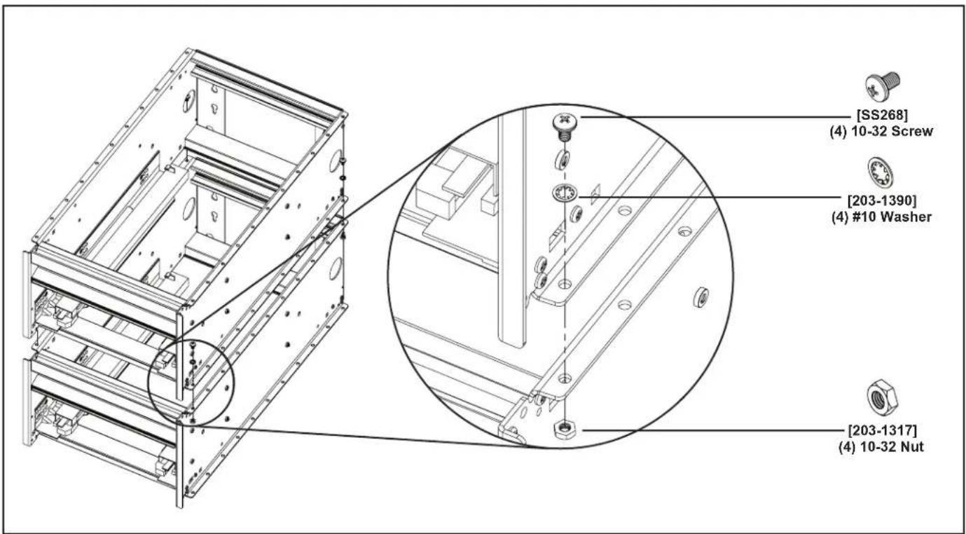
Place the one Cartesian vanity on top of another. Install 4 screws (SS268) and 4 washers (203-1390) into the holes closest to the front and back edge. Using the 4 nuts (203-1317) tighten the assembly until firmly secure.
OPTIONAL GANGING KIT
If you are not Stacking and/or Ganging Cartesian or Profiles, you may skip this step and continue to assembling the glass drawer front on page 15.
If you purchased the optional side kits, continue to page 13. For the optional Alcove Kit continue to page 12.
Assemble frames on a clean level surface BEFORE installing on the wall.
- Install 4 bolts (203-1302) and 4 washers (203-1301) into the square holes near the top and bottom edge of the side pan.
- Place the 4 spacers (R290) over the bolts and bring the adjoining pan in location to slide the bolts into the corresponding holes.
- Using the 4 nuts (203-1261) tighten the assembly until firmly secure.
- Slide the Filler/Bumper down over the flanges. If loose, pinch using needle nose pliers as shown below.
ALCOVE AND CORNER INSTALLATIONS
See Alcove kit instructions for greater clarity.
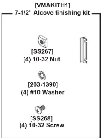
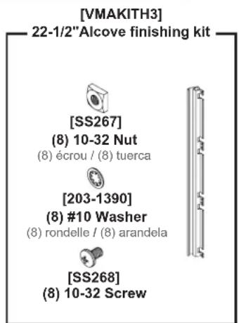
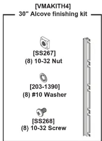
Note: The Alcove Kit you order depends on the overall height of your vanity or vanity stack combination. For example, if you stack two H2 vanities (15'' + 15'' = 30'') you would use the VMAKITH4. One Alcove kit is required per side.
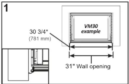
Alcove Installations - For standard top sizes (Nominal + 1") Two Alcove Kits, VMAKIT are used in place of side kits when installing the vanity into an alcove. Each Alcove kit adds 3/8 to the overall nominal width of the vanity. The wall opening should be 1 gap larger to allow 1/8 gap on either side of the Alcove kit. Fig. 1 Shows the dimension for a VM30 as an example.
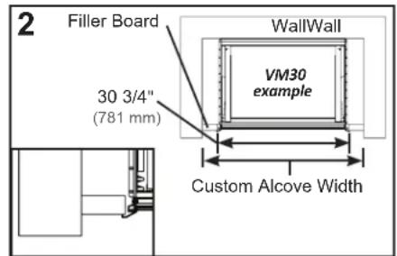
Alcove Installations -Requiring extra fillers Two Alcove Kits, VMAKIT are used in place of side kits when installing the vanity into an alcove. Each Alcove kit adds 3/8 to the overall nominal width of the vanity. Field installed extra filler to match the wall (Fig. 2).
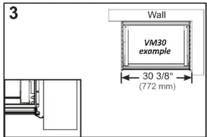
Corner Installation - One Alcove Kit, VMAKIT is used with a single side kit when installing the vanity into a corner. Each Alcove kit adds 3/8" to the overall nominal width of the vanity. Fig. 3 Shows the dimension for a VM30 with one Alcove kit as an example.
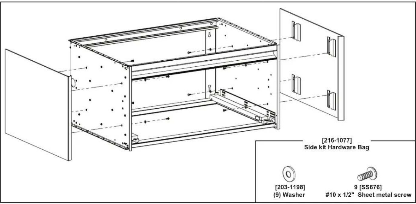
OPTIONAL SIDE KIT
Use the #10 CB-SS676 screws and washer CB-203-1198 provided to attach the side glass panels.
OPTIONAL SELECTABLE NIGHT LIGHT
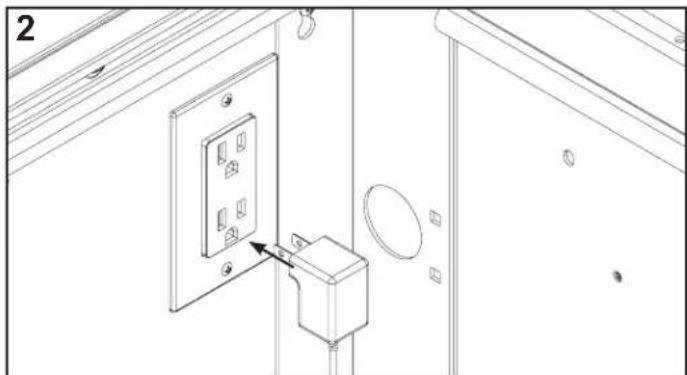
Note: The Night Light is preinstalled to a default color setting of 2700K. If 2700K is your desired color temperature, proceed to step 2. If 4000K is your desired color temperature you must complete step 1.
- To select the 4000K color temperature you must disconnect the power supply from the 2700K wires located on the inside of the vanity. Once located, disconnect the wires labeled 2700K and connect the wires labeled 4000K.
- Plug in the power supply into the wall and test.
- Neatly restrain wires to avoid interference with drawer or drawer slides.
Note: When installing multiple night lights, a power strip can be used.

Part no. 209-1232-E-Cartesian, Profiles H2 rev. 05/16/18 Cartesian "Vanity, Profiles" "Vanity
ACCESSORY INSTALLATION
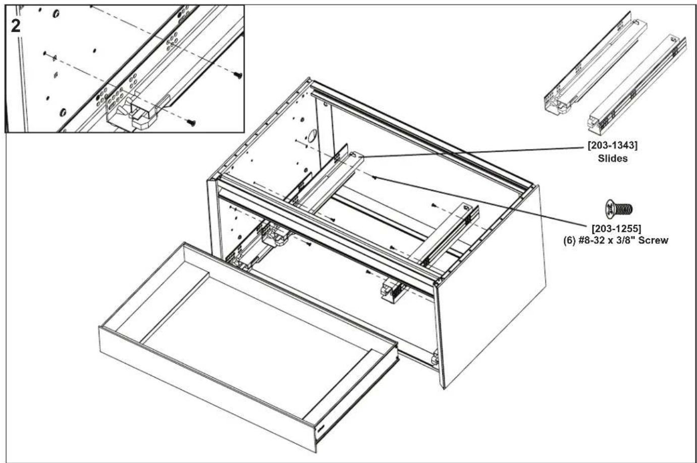
Install the optional Slim Printer Insert slides before installing the countertop or plumbing. See Page 15.
If you have the optional night light plug the unit in and test.
See separate instructions for VAELECTRIC accessory.
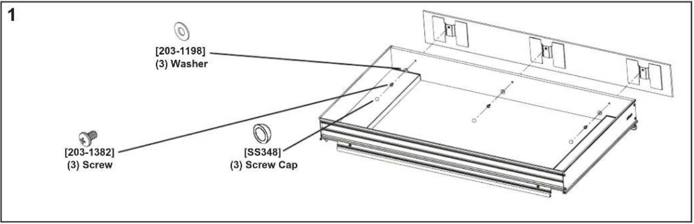
OPTIONAL SLIM DRAWER INSERT
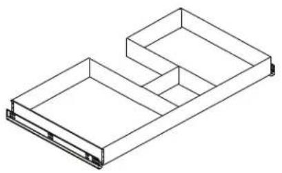
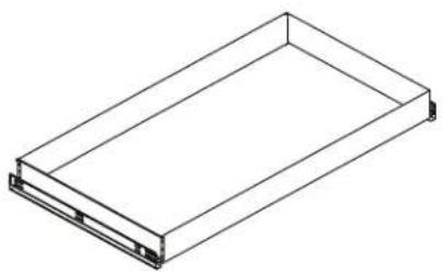
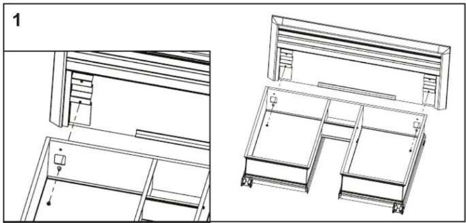
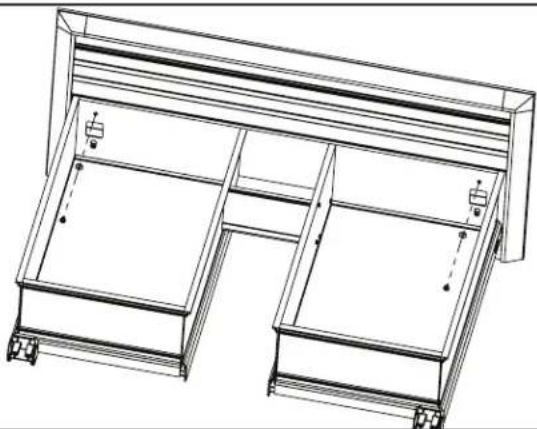
- Thread the screw and washer through the holes inside the drawer to the glass front (Fig. 1).
- Install the optional Slim Printer using the screws and slides provided (Fig. 2).
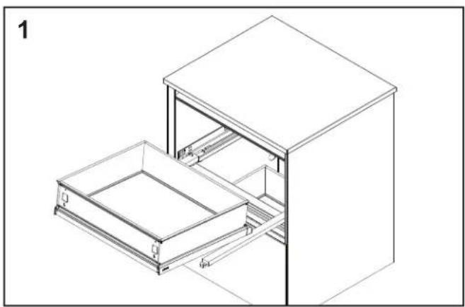
DRAWER INSTALLATION
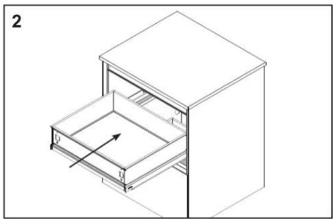
- Lay the drawer onto the drawer slides as shown (Fig.1).
- Push the drawer in until an audible sound, a series of clicks, is heard on each side (Fig. 2).
- Ensure that the locking pin on the back of the drawer slides engage the drawer on both sides, and that the clips are firmly engaged before letting go of the drawer.
GLASS DRAWER FRONT
If you are installing VAELECTRIC, see separate instructions before installing the glass drawer fronts.
Install the countertop and plumbing before installing the glass drawer fronts.
- The drawer front is first hung from two keyholes on each side of the drawer box. Install 2 #8-32 x 1/2" screws (203-1219) WITHOUT washers on the bottom of each bracket in the drawer front (Fig. 1).
- Hang the drawer front on the drawer box and install the remaining screws WITH washers into the two remaining threads in the drawer front bracket (Fig. 2). Tighten the screws tightly after the drawer front is level and even with the side kits.
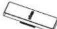
- Snap the screw covers over the screws by squeezing gently at "Robern".

[216-1074]
Drawer front Hardware Bag
[203-1219]
(4) #8-32 x 1/2" Screw

[203-1198]
(4) Washer
[211-1095]
(2) Screw cover
2
3
ADJUSTING DRAWER FRONTS
Note: Proper installation is very important for proper drawer front alignment on Robern vanities. Making sure the vanity is level and square in all directions is very important.
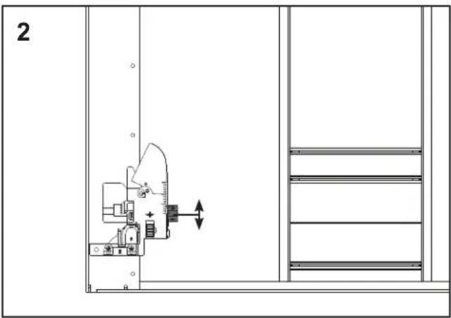
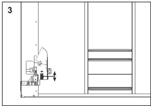
- Loosen the drawer front mounting screws (refer to page 15) to make rough adjustments. Adjust the front both vertically and horizontally. Once aligned, tighten the screws. When working with multiple drawers, do this step on all drawer fronts before proceeding.
- Fine adjustments can be done with the adjustment features incorporated in the locking clips. Height adjustment of the drawer front is done with the slider. Each side may be adjusted independently.
- Fine adjustment of left to right adjustment can be done. It is recommended to adjust both wheels in the same direction by equal amounts.
DRAWER REMOVAL
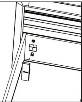
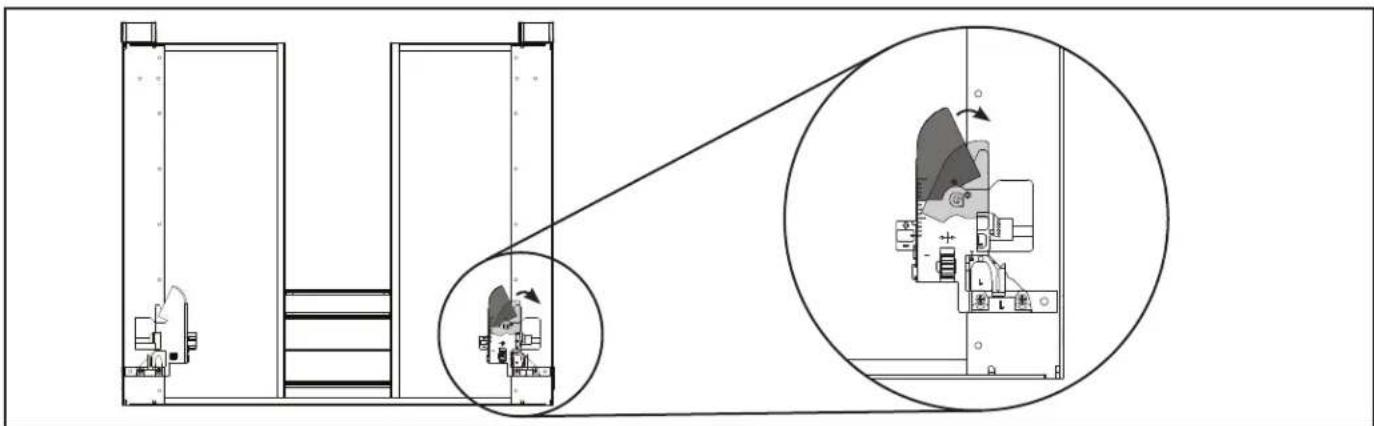
- If a drawer needs to be removed, no tools are required. Look at the image of the drawer clips below. This view is looking up at the bottom of the drawer.
- Reaching under each side of the drawer, pull the levers on the locking devices to disengage the clips, and pull out the drawer.
! Caution: You will now be carrying the weight of the drawer! - Place the drawer in a safe location so no damage occurs.
USE AND MAINTENANCE
The vanity sides, drawer front and interior are constructed of glass and aluminum. Use only a damp cloth to clean. Ammonia or vinegarbased cleaners can damage mirrors.
A 50/50 solution of water and isopropyl alcohol is recommended for cleaning the vanity. A mild detergent may be used on the surfaces.
When cleaning, spray the cloth, not the vanity, mirror, or surround surfaces. Do not use abrasive cleansers on any part of the vanity.

WARRANTY
Limited Warranty One Year Term
Robern warrants to the original purchaser that, it will, at its election repair, replace, or make appropriate adjustment to products made by this company shown to have significant defects in material or workmanship which are reported to Robern in writing within one (1) year from the date of delivery. Robern is not responsible for installation costs. The warranty is void in the event the product is damaged in transit, or if damage or failure is caused by abuse, misuse, abnormal usage, faulty installation, damage in an accident, improper maintenance, or any repairs other than those authorized by Robern. At the expiration of the one year warranty period, Robern shall be under no further obligation under any warranty, expressed or implied, including the implied warranty of merchantability. Robern shall not be liable for any consequential damages arising out of or in connection with the use or performance of its products. Some states do not allow limitations on how long an implied warranty lasts or do not allow the exclusion or limitation of incidental or consequential damages, so the above limitation or exclusion may not apply to you. Any liability against Robern under any implied warranty, including the warranty of merchantability, is expressly limited to the terms of this warranty. Permission to return any merchandise under this warranty must be authorized by Robern and returned prepaid by the purchaser. Claims under this warranty should be sent directly to your dealer.
©2016 Robern, Inc.
ALL RIGHTS RESERVED
Kits secondaires vendus séparément Kits secundarios se venden por separado
CONTENU CONTENIDO
© Robern, Inc., 2016.
TOUS DROITS RÉSERVÉS
© Robern, Inc., 2016.
TODOS LOS DERECHOS RESERVADOS