YT-23305 - Compressor Yato - Free user manual and instructions
Find the device manual for free YT-23305 Yato in PDF.

| Product Type | Oil compressor |
| Brand | Yato |
| Model | YT-23305 |
| Nominal voltage | 230-240 V ~ |
| Nominal frequency | 50 Hz |
| Nominal power | 1500 W |
| Tank capacity | 50 L |
| Nominal pressure | 0.8 MPa / 8 bar / 116 PSI |
| Air flow (max pressure) | 200 L/min |
| Sound pressure level | 74.2 dB(A) |
| Sound power level | 93.7 dB(A) |
| Weight | 31 kg |
| Insulation class | I |
| Protection degree | IP20 |
| Recommended oil type | ISO VG 100 |
| Oil capacity | Approximately 0.3 L (check gauge) |
| Air filter | Yes, washable |
| Safety valve | Factory set, non-adjustable |
| Overload protection | No (model YT-23305) |
| Intended use | Powering pneumatic tools, inflation, painting |
| Operating temperature | +5 °C to +40 °C |
| Routine maintenance | Drain condensate after each use, change oil every 50 h |
Frequently Asked Questions - YT-23305 Yato
User questions about YT-23305 Yato
0 question about this device. Answer the ones you know or ask your own.
Ask a new question about this device
Download the instructions for your Compressor in PDF format for free! Find your manual YT-23305 - Yato and take your electronic device back in hand. On this page are published all the documents necessary for the use of your device. YT-23305 by Yato.
USER MANUAL YT-23305 Yato
natural_image
Close-up of a spherical mechanical component mounted on a metal frame with black connectors (no visible text or symbols)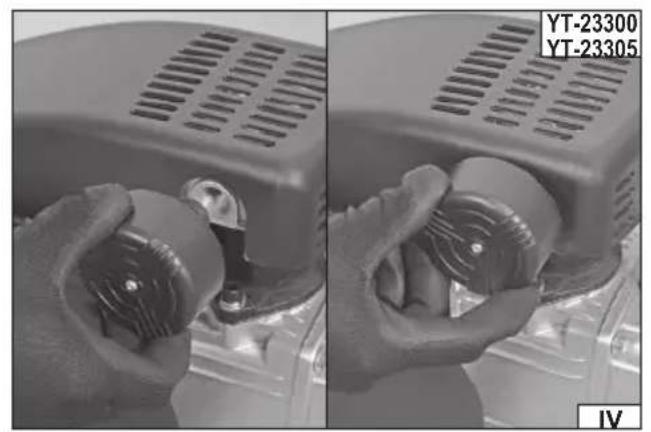
natural_image
Close-up of hands holding a mechanical component, showing internal components and a circular housing (no text or symbols visible)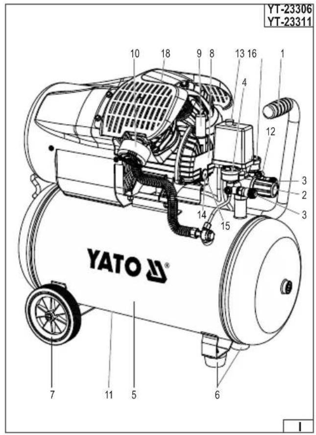
natural_image
Close-up of a jet landing gear with visible tire and hub (no text or symbols)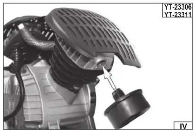
natural_image
Close-up of a mechanical component with a dial indicator and label (no readable text or symbols)natural_image
Close-up of hands adjusting a mechanical component with a threaded fitting (no visible text or symbols)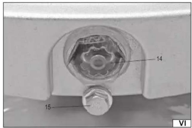
natural_image
Close-up of a pressure regulator with a gauge and valve, mounted on a metal shelf (no visible text or symbols)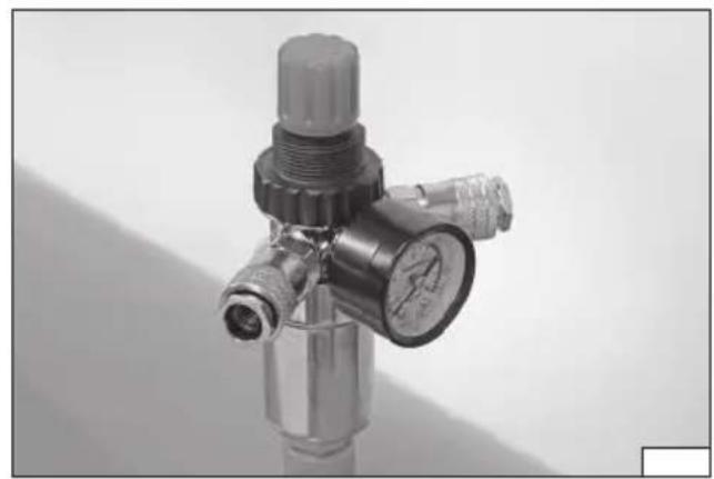
natural_image
Close-up of a metallic pressure regulator valve with threaded port and valve fittings (no visible text or symbols)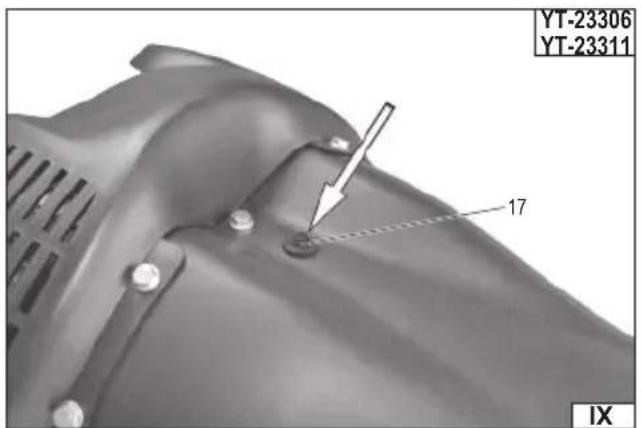

natural_image
Close-up of a mechanical valve assembly with a metallic connector and tubing (no visible text or symbols)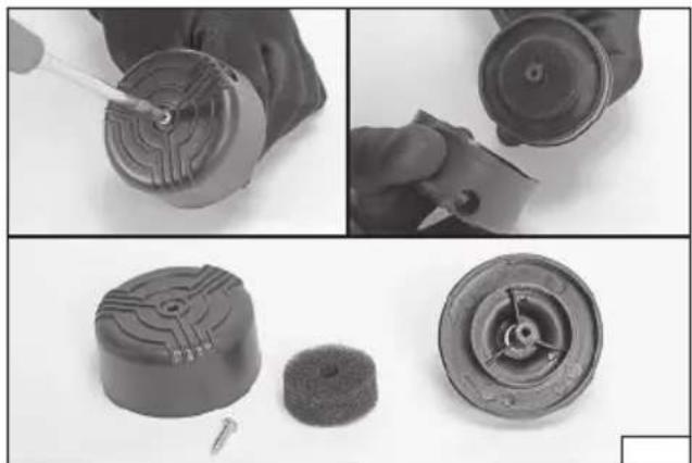
natural_image
Three-panel image showing a hand holding a small mechanical component, with close-ups of the final and side views (no text or symbols visible)PL
- handle
- pressure regulator
- quick coupler
- outlet pressure gauge
- pressure tank
- footer
- wheel
- crankcase
- oil cap
- air fi lter
- condensate drain plug
- safety valve
- switch
- oil gauge
- oil drain plug
- tank pressure gauge
- overload switch
- cover
DE
Read the operating instruction
Wear protective goggles
Wear hearing protectors
Direction of rotation
Drehrichtung
Warning! The compressor unit can start without a warning
Warning! Risk of high temperatures
Prohibition: Do not open the plug before connecting the air hose
Prohibition: Do not operate the portable compressor with the open door or open housing
This symbol indicates that waste electrical and electronic equipment (including batteries and storage cells) cannot be disposed of with other types of waste. Waste equipment should be collected and handed over separately to a collection point for recycling and recovery, in order to reduce the amount of waste and the use of natural resources. Uncontrolled release of hazardous components contained in electrical and electronic equipment may pose a risk to human health and have adverse effects for the environment. The household plays an important role in contributing to reuse and recovery, including recycling of waste equipment. For more information about the appropriate recycling methods, contact your local authority or retailer.
WYPOSAŻENIE PRODUKTU
PRODUCT CHARACTERISTICS
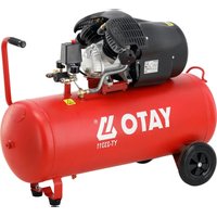
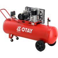
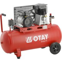
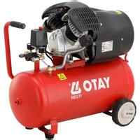
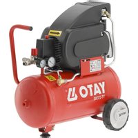
An oil compressor is used to compress atmospheric air. It can also power pneumatic tools, such as blow guns, pumps, and paint sprayers. Proper, reliable, and safe operation of the device depends on proper operation, therefore:
Before using this product, read the entire manual and retain it. If you pass on this product to someone else, pass it on to them along with this manual. This manual should always be kept with the device and be accessible to the operator.
The supplier is not liable for any damage or injury resulting from use of the product other than its intended purpose, failure to follow safety regulations, or failure to follow the instructions in this manual. Maintenance activities not described in the manual, changes to the mechanical or electrical structure, and other modifications will void the user's warranty and guarantee rights.
PRODUCT EQUIPMENT
The product is delivered complete, but assembly or appropriate adjustment is required as described later in the user manual.
TECHNICAL DATA
| Parameter Unit of measurement Value | |||||
| Catalog number YT-23300 YT-23305 YT-23306 YT-23311 | |||||
| Nominal voltage [V~] 230-240 230-240 230 | 230 | ||||
| Nominal frequency [Hz] 50 50 50 50 | |||||
| Short circuit current | [A] | 36 36 55 55 | |||
| Load current | [A] | 6,2 | 6,2 | 9,3 | 9,3 |
| Rated power | [W] | 1500 | 1500 | 2200 | 2200 |
| Rated engine speed | [min-] | 2850 | 2850 | 2850 | 2850 |
| Tank capacity | [I] | 24 50 50 | 100 | ||
| Nominal pressure | [MPa / bar / PSI] | 0,8 / 8,0 / 116 | 0,8 / 8,0 / 116 | 0,8 / 8,0 / 116 | 0,8 / 8,0 / 116 |
| Pumping capacity (max. pressure) | [l/min] | 200 200 412 412 | |||
| Noise level | |||||
| - Sound pressure L_mA ± K | [dB(A)] | 74,2 ± 3,0 | 74,2 ± 3,0 | 75,1 ± 2,11 | 75,1 ± 2,11 |
| - Sound power L_mA ± K | [dB(A)] | 93,7 ± 2,23 | 93,7 ± 2,23 | 95,1 ± 2,11 | 95,1 ± 2,11 |
| Mass [kg] 23 | 31 42 52 | ||||
| Insulation class | I | I | I | I | |
| Degree of protection | IP20 | IP20 | IPX0 | IPX0 | |
The declared noise emission value has been measured using a standard test method and can be used to compare one tool with another. The declared noise emission value can be used in a preliminary exposure assessment.
Note: Safety measures to protect the operator must be defined and are based on an assessment of exposure to emissions under actual conditions of use (including all parts of the operating cycle, such as the time when the tool is switched off or idling, and the time of activation).
SAFETY INSTRUCTIONS
Learn how to operate your device. Do not operate or charge the device before reading the user manual. Following the instructions in this manual reduces the risk of injury, electric shock, or fire.
The device is intended for indoor use only and should not be exposed to atmospheric precipitation.
The device is not intended for use in potentially explosive atmospheres with high humidity and dust levels. The operating temperature should be between +5°C and +40°C, and relative humidity should not exceed 80%. The device should not be operated near areas where water is being sprayed.
Operating the unit at too low a temperature can cause the lubricants to lose their properties and prevent proper lubrication of the unit's systems. Operating at temperatures below 0^ C can cause condensate to freeze inside the tank. Warning! During a cold start, high oil viscosity, clogged oil filters, or malfunctioning valves can cause oil starvation.
The device should only be placed on a hard, even and fl at surface.
Please ensure that the ventilation openings in the device housing are not covered during and after operation.
During operation, some housing components may become very hot, and touching them may cause burns. Do not use the compressor without protective covers. When carrying the device, hold it only by its handle. Before carrying, the device must be turned off. The switch must be in the off position and the power cord must be unplugged. The device must not be transported with the tank under pressure.
Observe the maximum pressure of the pumped product. Use a pressure gauge (built-in or separate) to monitor the pressure inside
EN
the pumped product. Exceeding the maximum pressure may cause damage to the pumped product or even rupture it. A burst product can cause serious injury.
Periodically check whether the readings of the pressure gauge built into the device agree with the readings of the calibrated pressure gauge.
Inspect the tool for damage before each use. If you notice any cracks, abrasions, or other damage, do not use the device until it is repaired.
The device is designed to operate only with flexible pressure hoses. Hoses connected to the device should be capable of with-standing at least the pressure generated by the compressor. Hoses for pressures higher than 7 bar / 0,7 MPa should be equipped with a safety cord, e.g., wire rope.
Before connecting the hose to the device, inspect it for damage. If the coating is worn, cracked, or air leaks are noticed, discontinue use and replace the damaged hose before continuing work.
Never bend or twist the hose while working. Kinking the hose can reduce its internal diameter, even to the point of blocking airflow. This can damage the hose or even rupture it, which can cause serious injury. Bending or twisting the hose also accelerates its wear. Never use the hose to carry a tool. Do not overtighten the hose while working.
Avoid creating long lines for compressed air. Shorter lines are easier to inspect.
All devices and accessories connected to the compressor should withstand at least the pressure that the compressor is capable of generating.
Do not attempt to adjust or modify the safety valve yourself. An improperly adjusted or modified safety valve may cause damage to the product, which could result in serious injury.
Do not use the device as an artificial respiration device, for spraying any substance, or for any other purpose not described in the instruction manual. The compressor may only be used to compress air. Compressing other gases is prohibited.
Never direct the airflow towards yourself or other people or animals. Do not use your finger or any other part of your body to check whether the device is pumping air.
Make sure the appliance is turned off before connecting the hose and accessories to the appliance. Children and pets should be kept away from the appliance while it is in operation. This appliance is not intended for use by children.
The device should be used, transported, and stored in an upright position. Using, transporting, or storing the device in any position other than upright may result in damage to the product.
Recommendations for connecting the device to the power supply
Before connecting the device to the power supply, ensure that the voltage, frequency, and capacity of the mains supply correspond to the values indicated on the rating plate. The plug must fit the socket. Do not modify the plug or socket to fit any other purpose. The device must be plugged directly into a single mains outlet. The mains circuit must be equipped with a protective conductor and 16A fuse. If extension cords are used, a three-wire extension cord with a 16A current rating must be used.
Avoid contact between the power cord and sharp edges, hot objects, and surfaces, including those on the device itself. Always fully unwind the power cord when the product is in operation, and position it so that it does not obstruct operation. The power cord should not pose a tripping hazard. The power outlet should be located so that the product's power plug can be quickly disconnected. When disconnecting the power cord, always pull on the plug housing, never on the cable. Do not allow the power cord to come near a hot device. If the power cord or plug becomes damaged, immediately disconnect it from the mains and contact an authorized manufacturer's service center for a replacement. Do not replace the power cord yourself. Do not use the product with a damaged power cord or plug. The power cord or plug cannot be repaired; if damaged, replace them with new, fault-free ones.
PRODUCT SERVICE
Preparing for work
Note: All steps in this section must be performed with the product disconnected from the power supply. Make sure the power cord is unplugged from the power outlet.
The product should be unpacked, completely removing all packaging components. It is recommended that you retain the packaging; it may be useful for future transportation and storage. Inspect the product for damage. If any damage is found, do not use the product until the damage is repaired or the damaged components are replaced with new, damage-free components.
Product assembly
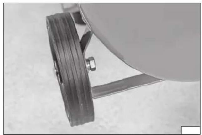
NOTE! Before first use, check that all screw connections are properly tightened, especially the screws in the head and compressor body. Depending on the model, screw the foot, feet (II), and wheels (III) into the base of the tank. Attach the foot to the base hole with a screw. Insert the screw from the bottom, use washers, and tighten the nut. Tighten using a suitable wrench. Attach the wheels (III) to the right and left sides of the compressor base with screws. Apply washers from the inside, and tighten the nuts. Tighten using a suitable wrench. Ensure the components are securely fastened.
Air fi Iter installation (IV)
Before first use, the air filter must be installed in the product. To do this, remove the air filter cap. Screw the air filter clockwise into the hole located in the compressor cylinder head.
For product number YT-23306 and YT-23311, install the filters on both sides of the compressor.
EN
Compressor setting
The compressor should be placed on a level, flat, and stable surface, away from flammable substances, in a well-ventilated room protected from the elements. The compressor should be positioned approximately 2,5 meters from walls and objects.
Checking the oil level / topping up
NOTE! The transport plug must be removed and the oil plug (V) screwed in. Before starting work, check the oil level on the dipstick (VI). If necessary, top up the oil to bring the level to the center of the eyelet. Too low an oil level (below the bottom of the eyelet) creates the risk of the pump seizing. Too high an oil level (at the top of the eyelet) or using the wrong type of oil creates the risk of oil and air entering the pneumatic system.
Air compressor oil with a viscosity of ISO VG 100 should be used in the compressor.
The factory oil should be changed after 10 hours of compressor operation. Oil changes are described later in this manual.
Connecting the compressor to the electrical supply
Make sure the compressor switch is in the off position (press the switch down). Plug the compressor into an electrical outlet.
Compressor Operation
Connect the hoses with the pneumatic tools you will be using for work to the quick couplers. Make sure the pneumatic tool switch is in the off position.
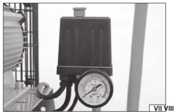
Turning the compressor on/off (VII)
To turn on the compressor, set the switch to the on position (pull the switch upward). The compressor will start, filling the tank to the factory-set pressure specified in the technical data table. During operation, the amount of air used depends on the type of tools used. The device operates in automatic mode, maintaining the factory-set pressure level in the tank. To turn off the compressor, set the switch to the off position (press the switch down).
Adjusting the working pressure
Do not exceed the maximum pressure specified in the specifications for the connected tools and hoses. Please check the permissible value in the tool manufacturer's technical specifications.
Using the pressure regulator (VIII) Set the appropriate outlet pressure. The compressor is equipped with two pressure gauges. The set outlet pressure can be read on the pressure gauge located under the regulator. The tank pressure can be read on the pressure gauge located under the compressor switch (VII).
Overload protection
Products with catalog numbers YT-23306 and YT-23311 are equipped with an electric motor overload protection system. The overload protection activates at high motor temperatures. If the protection is activated, the device will automatically shut off. To restart the device, turn off the compressor by moving the switch to the off position. Wait for the device to cool. Before restarting, press the overload switch located on the compressor housing (IX). Restart the compressor using the switch.
MAINTENANCE
CAUTION! Before beginning maintenance, allow the device to cool completely. Turn off the compressor using the power switch, then disconnect the power cord from the wall outlet.
Remove air and condensate from the tank as described in the „Draining Condensate from the Tank „ section of the manual. This should be done thoroughly and after each use of the compressor. Otherwise, the water may cause the tank to rust, which will result in damage. Water separation from the air is a natural phenomenon associated with temperature changes. Therefore, do not neglect draining the tank. The compressor tank cannot be welded or repaired. If you notice damage to the tank, contact an authorized manufacturer's service center. Do not operate a damaged compressor.
Wipe the device's casing with a slightly damp cloth and then dry. Clean the air inlet and outlet areas with a compressed air jet at a pressure of no more than 0.3 MPa. Ventilation openings can also be cleaned with a brush or a soft plastic brush. Do not use alcohol, solvents, acids, or caustic substances for cleaning. After cleaning and performing the necessary maintenance and service activities, the compressor is ready for further operation or storage. All other maintenance and service activities not described in the operating instructions must be performed by an authorized manufacturer's service center. If you notice any malfunctioning of the compressor or wear of parts that reduce the device's performance, do not attempt repairs yourself or operate a damaged compressor. For repairs, contact an authorized manufacturer's service center.
CURRENT MAINTENANCE OPERATIONS
CAUTION! Before beginning any maintenance, allow the device to cool completely. Turn off the compressor using the power switch and then disconnect the power cord from the power outlet.
After the first 50 hours, check whether all screw connections are properly tightened, especially the screws in the head and compressor housing.
EN
Emptying the condensate from the tank (X)
After completing work, it is recommended to empty the pressure tank daily of any condensate, oil, water, and solid particles through the valve. Before emptying, turn off the compressor and unplug the power cord. Release any pressure from the tank, for example, using a blow-out gun. Point the blow-out gun at a safe location (away from people and animals) and press the trigger until the tank is empty. Then, place a flat container under the drain plug. Unscrew the condensate drain plug counterclockwise, located on the bottom of the tank. After emptying the condensate tank, tighten the drain plug securely. Do not pour condensate into the ground, rivers, lakes, or sewers. Dispose of the condensate at an environmentally hazardous substances collection point.
Oil change
The compressor oil should be changed after every 50 hours of operation or when the oil level indicator shows that the oil is exhausted (black). Use air compressor oil with an ISO VG 100 viscosity in the compressor.
To change the oil, turn off the compressor and unplug the power cord. Prepare a suitable container under the oil drain plug (VI) to prevent oil from spilling onto the compressor components or the ground when draining the tank. Use a wrench to unscrew the oil drain plug. If the oil does not drain completely, tilt the compressor slightly. After draining the oil tank, tighten the oil drain plug. Pour in new oil until the level is in the center of the filler hole. Do not mix different types of oil. Too low an oil level (below the bottom of the filler hole) poses a risk of pump seizure.
Too high an oil level (top of the mesh) or using the wrong type of oil creates the risk of oil and air entering the pneumatic system. Do not pour oil into the ground, rivers, lakes, or sewers. Dispose of used oil at a collection point for environmentally hazardous substances.
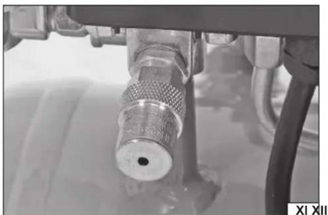
Safety valve (XI)
The safety valve is factory-set to the maximum allowable pressure in the compressor tank. Do not attempt to adjust the safety valve yourself. If the safety valve is not operating properly, contact an authorized manufacturer's service center. Check the valve for proper operation approximately every 30 hours of operation or at least three times a year. Turn off the compressor and unplug the power cord. Unscrew the perforated outlet nut of the safety valve counterclockwise. Carefully pull the nut outward with your hand. If the valve releases air, it is operating properly. Tighten the perforated nut by turning it clockwise. Ensure the nut is securely tightened.
Cleaning the air filter
The air filter prevents dust and dirt from being drawn into the compressor. The air filter becomes dirty depending on the conditions and operating time of the compressor. The filter should be checked for contamination once a month, and if it requires cleaning, it should be cleaned or replaced at least every 50 hours of compressor operation. A clogged intake filter can significantly reduce compressor performance and lead to damage to the device. It is prohibited to operate the compressor without a properly installed air filter. Contaminants entering the compressor with the air can damage it.
In the device, unscrew the filter counterclockwise by hand, remove the retaining screw from the air filter housing (XII), open the housing, and pull the filter out of the housing. Clean the filter in a soapy water solution, rinse it in water, and dry it thoroughly. Place the filter in the housing, assemble the two housing halves, and tighten the retaining screw. Screw the air filter clockwise by hand into the air filter opening. Make sure the air filter is properly installed.
STORAGE AND TRANSPORT
Transport the device by its handle or base. When transporting it by means of transport, secure the compressor against movement. Transport and store the device only when it is turned off, disconnected from the power supply, and with the air tank empty. Store the device in enclosed, well-ventilated rooms. During storage and transport, the device should not be exposed to direct sunlight, heat sources, or precipitation. The storage location should prevent unauthorized access, especially to children. Do not place anything on the device.
NOTE! After each transport and after every 50 hours of operation, check that all screw connections are properly tightened.
PRODUKTMERKMALE
PRODUKTA RAKSTUROJUMS
TEKOŠAS APKOPES DARBIBAS
CARACTÉRISTIQUES DU PRODUIT
DEKLARACJA ZGODNOŚCI DECLARATION OF CONFORMITY DECLARATIE DE CONFORMITATE
1025/YT-23300/EC/2025
We declare and guarantee with full responsibility that the following products:
meet requirements of the following European Standards / Technical Specifications:
EN IEC 61000-6-3:2021
and fulfill requirements of the following European Directives:
Machinery and safety elements
Restriction of the Use of Certain Hazardous Substances
Serial number: concern all serials numbers of item(s) mentioned in this declaration
The person authorized to compile the technical file:
DEKLARACJA ZGODNOŚCI DECLARATION OF CONFORMITY DECLARATIE DE CONFORMITATE
0925/YT-23300/EC/2025
We declare and guarantee with full responsibility that the following products:
meet requirements of the following European Directive: 2000/14/EC
Manufacturer quality-control system, examination of the manufacturer's technical file and periodical inspection by notified body
Measured sound power level on an equipment representative for this type:
Guaranteed sound power level for this equipment:
conformity and references of the other Community Directives applied:
Name and address of the person authorized to keep the technical file:
DEKLARACJA ZGODNOŚCI DECLARATION OF CONFORMITY DECLARATIE DE CONFORMITATE
1025/YT-23306/EC/2025
We declare and guarantee with full responsibility that the following products:
meet requirements of the following European Standards / Technical Specifications:
EN IEC 61000-6-3:2021
and fulfill requirements of the following European Directives:
Machinery and safety elements
Restriction of the Use of Certain Hazardous Substances
Serial number: concern all serials numbers of item(s) mentioned in this declaration
The person authorized to compile the technical file:
DEKLARACJA ZGODNOŚCI DECLARATION OF CONFORMITY DECLARATIE DE CONFORMITATE
0925/YT-23306/EC/2025
We declare and guarantee with full responsibility that the following products:
meet requirements of the following European Directive: 2000/14/EC
Manufacturer quality-control system, examination of the manufacturer's technical file and periodical inspection by notified body
Measured sound power level on an equipment representative for this type:
Guaranteed sound power level for this equipment:
conformity and references of the other Community Directives applied:
Name and address of the person authorized to keep the technical file: