
DW313000 - Welding machine Campbell Hausfeld - Free user manual and instructions
Find the device manual for free DW313000 Campbell Hausfeld in PDF.

| Product Type | Wire Feed Welder (MIG/FCAW) |
| Brand | Campbell Hausfeld |
| Model | DW313000 |
| Rated Input Voltage | 120 V |
| Frequency | 60 Hz |
| Phase | Single |
| Maximum Input Current | 20.5 A |
| Maximum Open Circuit Voltage | 37 V |
| Output Current/Voltage | 80 A / 18 V at 20% duty cycle; 45 A / 16.25 V at 60%; 30 A / 15.5 V at 100% |
| Usable Wires | Flux-cored wire 0.8 mm or 0.9 mm; Solid MIG wire 0.6, 0.8, 0.9 mm |
| Insulation Class | H |
| Net Weight | 20.3 kg |
| Dimensions (L x W x H) | 52 cm x 28 cm x 33.2 cm |
| Duty Cycle | 20% at 80 A, 60% at 45 A, 100% at 30 A |
| Thermal Protection | Thermostat with amber light |
| Wire Feed | Continuous speed control |
| Polarity | Adjustable (positive or negative) |
| Gas Required (GMAW) | Inert, non-flammable (Ar, CO2, blends) |
| Warranty | 5 years transformer/rectifier, 90 days accessories |
| Included Accessories | 0.8 mm flux-cored wire spool, contact tips, hex key |
| Maintenance and Cleaning | Before each use: check cables, tip, nozzle. Every 3 months: blow dust, clean roller, replace labels. |
| Safety | Wear protective equipment (helmet, gloves, flame-resistant clothing). Ensure ventilation. Keep 35 feet away from flammable materials. |
Frequently Asked Questions - DW313000 Campbell Hausfeld
User questions about DW313000 Campbell Hausfeld
0 question about this device. Answer the ones you know or ask your own.
Ask a new question about this device
Download the instructions for your Welding machine in PDF format for free! Find your manual DW313000 - Campbell Hausfeld and take your electronic device back in hand. On this page are published all the documents necessary for the use of your device. DW313000 by Campbell Hausfeld.
USER MANUAL DW313000 Campbell Hausfeld
CH CAMPBELL HAUSFELD®
Wire Feed Arc Welder
Operating Instructions and Parts Manual
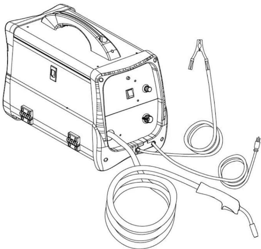
natural_image
Line drawing of a portable electronic device with coiled cables and connectors (no text or symbols)Model: DW3130
CH CAMPBELL HAUSFELD.
Please read and save these instructions. Read carefully before attempting to assemble, install, operate or maintain the product described.
Protect yourself and others by observing all safety information. Failure to comply with instructions could result in personal injury and/or property damage! Retain instructions for future reference.
REMINDER: Keep your dated proof of purchase for warranty purposes! Attach it to this manual or file it for safekeeping.
Model #: ____
Serial #: ____
Purchase Date: ____
For parts, product & service information visit www.campbellhausfeld.com
Campbell Hausfeld 100 Production Drive Harrison, Ohio 45030
REGISTER YOUR PRODUCT ONLINE NOW! www.campbellhausfeld.com/reg READ AND FOLLOW ALL INSTRUCTIONS • SAVE THESE INSTRUCTIONS • DO NOT DISCARD

/CampbellHausfeld

CHcompressors

CHcompressors

@CHCompressors

CHcompressors

CampbellHausfeld
BEFORE YOU BEGIN
Description
These Campbell Hausfeld wire feed welders are designed to be used on standard 120V outlets. The welder is equipped with infinite wire speed control to accurately select the proper wire feed rate needed for various welding conditions. Internal components are thermostatically protected.
The DW3130 is designed for use with the Flux Cored Arc Welding (FCAW) or the Gas Metal Arc Welding (GMAW) process. As delivered from the factory, this welder can weld with .030 inch (0.8 mm) diameter flux core wire. A starter spool of .030 inch (0.8 mm) flux cored wire is included.
To use the GMAW process with the DW3130, it is necessary to purchase shielding gas and MIG wire only.
UNPACKING
After unpacking the unit, inspect carefully for any damage that may have occurred during transit. Check for loose, missing or damaged parts. Check to be sure all supplied accessories are enclosed with the unit. In case of questions, damaged or missing parts, please visit www.campbellhausfeld.com for customer assistance.
POWNTING
it if damaged during shipping, handling or use. Damage may result in bursting and cause injury or property damage.
Required Items - Not Included
• Gas Hose - 100 cm • Hose Clamp
- Flux Core Wire 0.8 mm, 0.2 kg Spool
- Hex Wrench
- Contact Tip 0.024 inch (0.6 mm) • Contact Tip 0.030 inch (0.8 mm)
- Contact Tip 0.035 inch (0.9 mm) • Gas Regulator
GENERAL SAFETY INSTRUCTIONS
Safety Guidelines
This manual contains information that is very important to know and understand. This information is provided for SAFETY and to PREVENT EQUIPMENT PROBLEMS. To help recognize this information, observe the following symbols.
△ DANGER
imminently hazardous situation which, if not avoided, WILL result in death or serious injury.
Warning
potentially hazardous situation which, if not avoided, COULD result in death or serious injury.
CAUTION
Caution indicates a potentially hazardous situation which, if not avoided, MAY result in minor or moderate injury.
NOTICE
Notice indicates important information, that if not followed, may cause damage to equipment.
IMPORTANT or NOTE: Information that requires special attention.
Safety Symbols
The following Safety Symbols appear throughout this manual to alert you to important safety hazards and precautions.
Risk of Fire
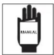
Read Manual First
Risk of Shock
Risk of Flying Fragments
Risk of Light Rays
Risk of Hot Parts
Risk of Explosion

Risk of Fumes
Risk of Magnetism
Wear eye protection
GENERAL SAFETY INSTRUCTIONS (CONTINUED)
California Proposition 65
This report can expose you to chemicals including lead, which are known to the State of California to cause cancer and birth defects or other reproductive harm. For more information go to www.P65Warnings.ca.gov.
This product, when used for welding, produces fumes or gases which contain chemicals known to the State of California to cause birth defects (or other reproductive harm) and, in some cases, cancer (California Health & Safety Code Section 25249.5 et seq.).
You are best when you cut, sand, drill or grind materials such as wood, paint, metal, concrete, cement, or other masonry. This dust often contains chemicals known to cause cancer, birth defects, or other reproductive harm. Wear protective gear.
Illinois Lead Poisoning Prevention Act
WARNING
CONTAINS LEAD. MAY BE HARMFUL IF EATEN OR CHEWED. COMPLIES WITH FEDERAL STANDARDS.
Circuit Requirements
CAUTION This equipment requires a dedicated 120 volts. Refer to the following chart for correct circuit breaker or fuse rating for 120 volt models. Do not run other appliances, lights or tools on this circuit while operating this equipment. Extension cords are not recommended. Blown fuses and tripped circuit breakers can result from failure to comply with this recommendation.
Important Safety Information
Please read and save these instructions. Read carefully before attempting to assemble, install, operate or maintain the product described. Protect yourself and others by observing all safety information. Failure to comply with instructions could result in personal injury and/or property damage! Retain instructions for future reference.
This manual contains important safety, operational and maintenance information. If you have any questions, please visit www.campbellhausfeld.com for customer assistance.
General Safety
WARNING
Always keep a fire extinguisher accessible while performing arc welding operations.
- Before starting or servicing any electric arc welder, read and understand all instructions. Failure to follow safety precautions or instructions can cause equipment damage and/or serious personal injury or death.
-
All installation, maintenance, repair, and operation of this equipment should be performed by qualified persons only in accordance with national, state, and local codes.
WARNING of electric arc welders can cause electric shock, injury, and death! Take all precautions described in this manual to reduce the possibility of electric shock. -
Verify all components of the arc welder are clean and in good condition prior to operating welder. Be sure insulation on all cables, torch and power cord is not damaged. Always repair or replace damaged components before operating the welder. Always keep welder panels, shields, etc. in place when operating welder.
• Always wear dry, protective clothing, welding gloves and insulated footwear when operating unit. - Always operate welder in a clean, dry, well ventilated area. Do not operate welder in humid, wet, rainy or poorly ventilated areas.
- Be sure work piece is properly supported and grounded prior to beginning any electric arc welding operation.
- Spread out coiled welding cable before use to avoid overheating and damage to insulation.
DANGER
Never immerse wire or torch in water. If welder becomes wet for any reason, be absolutely certain it is completely clean and dry before use!
• Always shut equipment off and unplug power cord prior to moving the unit.
• Always attach the work lead first.
- Verify work piece is securely grounded.
• Always shut off electric arc welding equipment when not in use and cut off any excess wire from torch.
- Never allow any part of the body to touch welding wire and ground or grounded work piece at the same time.
- Awkward welding conditions and positions can be electrically hazardous. When crouching, kneeling or at elevations, be sure to insulate all conductive parts, wear appropriate protective clothing and take precautions to prevent injury from falls.
- Never attempt to use this equipment at current settings or duty cycles higher than specified on equipment labels.
- Never use an electric arc welder to thaw frozen pipes.
Flying warning shot metal can cause injury. As welds cool, slag can be thrown off. Take all precautions described in this manual to reduce the possibility of injury from flying sparks and hot metal.
- Wear ANSI approved face shield or safety glasses with side shield protection when chipping or grinding metal parts.
- Wear ear plugs when welding overhead to prevent spatter or slag from falling into ears.
Electrical warning operations produce intense light and heat and ultraviolet (UV) rays. This intense light and UV rays can cause injury to eyes and skin. Take all precautions described in this manual to reduce the possibility of injury to eyes and skin.
- All persons operating this equipment or in the area while equipment is in use, must wear protective welding gear including: welding helmet or shield with at least shade 10 lens, flame resistant clothing, leather welding gloves and full foot protection.
⚠ WARNING Never look at arc welding operations without eye protection as described above. Never use a shade filter lens that is cracked, broken, or rated below number 10. Warn others in the area not to look at the arc.
Electric heating operations cause sparks and heat metal to temperatures that can cause severe burns! Use protective gloves and clothing when performing any metal working operation. Take all precautions described in this manual to reduce the possibility of skin and clothing burns.
- Make sure all persons in welding area are protected from heat, sparks and ultraviolet rays. Use additional face shields and flame resistant barriers as needed.
-
Never touch work pieces until completely cooled.
Hea, d. work introduced during electric arc welding and other metal working operations can ignite flammable and explosive materials! Take all precautions described in this manual to reduce the possibility of flames and explosions. -
Remove all flammable materials within 35 feet (10.7 meters) of welding arc. If removal is not possible, tightly cover flammable materials with fire proof covers.
- Do not operate any electric arc welder in areas where flammable or explosive vapors may be present.
• Take precautions to ensure flying sparks and heat do not cause flames in hidden areas, cracks, etc.
⚠ WARNING Fire hazard! Do not weld on containers or pipes that contain or have contained flammable materials or gaseous or liquid combustibles.
AtWARNING cylinders or containers such as tanks or drums can cause explosion if not properly vented! Verify that any cylinder or container to be welded has an adequate ventilation hole, so that expanding gases can be released.
Do in the fumes produced by arc welding operation. These fumes are dangerous. If welding area cannot be adequately ventilated, be sure to use an air-supplied respirator.
- Keep head and face out of welding fumes.
- Extremely toxic fumes are created when galvanized or cadmium plated metals or metals which contain zinc, mercury or beryllium are heated. Complete the following precautions before performing electric arc welding operations on these metals:
a. Remove coating from base metal.
b. Make sure welding area is well ventilated.
c. Use an air-supplied respirator.
The warning field generated during arc welding may interfere with the operation of various electrical and electronic devices such as cardiac pacemakers. Persons using such devices should consult with their physician prior to performing any electric arc welding operations.
- Route torch and work cables together and secure with tape when possible.
- Never wrap arc welder cables around the body.
• Always position torch and work leads on the same side of the body.
GENERAL SAFETY INSTRUCTIONS (CONTINUED)
- Exposure to electromagnetic fields during welding may have other health effects which are not known.
AlvWARNING welding area is secure and free of hazards (sparks, flames, glowing metal or slag) prior to leaving. Be sure equipment is turned off and excess wire is cut off. Be sure cables are loosely coiled and out of the way. Be sure all metal and slag has cooled.
DANGER
Cylinders can explode if damaged. Shielding gas cylinders contain gas under high pressure. If damaged, a cylinder can explode. Since gas cylinders are normally part of the welding process,
be sure to treat them carefully.
- Protect compressed gas cylinders from excessive heat, mechanical shocks and arcs.
- Install and secure cylinders in an upright position by chaining them to stationary support or equipment cylinder rack to prevent falling or tipping.
- Keep cylinders away from any welding or other electrical circuits.
- Never allow a welding electrode to touch any cylinder.
- Use only correct shielding gas cylinders, regulators, hoses and fittings designed for the specific application; maintain all parts properly.
- Turn face away from valve outlet when opening cylinder valve.
- Keep protective cap in place over valve except when cylinder is in use or connected for use.
- Read and follow instructions on compressed gas cylinders, associated equipment, and CGA publication P-1 listed in Safety Standards.
DANGER
le gasses with MIG welders. Only inert or non-flammable gasses such as carbon dioxide, argon, helium or mixtures of one or more of these gasses are suitable for MIG welding.
WARNING
Never lift cylinders off the ground by their valves or caps or with chains or slings.
Additional Safety Standards
ANSI Standard Z49.1 from American Welding Society, 550 N.W. Le June Rd. Miami, FL 33126
Safety and Health Standards
OSHA 29 CFR 1910, from Superintendent of Documents, U.S. Government Printing Office, Washington, D.C. 20402
National Electrical Code
NFPA Standard 70, from National Fire Protection Association, Batterymarch Park, Quincy, MA 02269
Code for Safety in Welding and Cutting
CSA Standard W117.2, from Canadian Standards Association, Standards Sales, 178 Rexdale Boulevard, Rexdale, Ontario, Canada M9W 1R3
Cutting And Welding Processes
NFPA Standard 51B, from National Fire Protection Association, Batterymarch Park, Quincy, MA 02269
Safe Practices For Occupational And Educational Eye And Face Protection
ANSI Standard Z87.1, from American National Standards Institute, 1430 Broadway, New York, NY 10018
Refer to Material Safety Data Sheets and manufacturers instructions for metals, wire, coatings and cleaners.
The DANGER, WARNING, CAUTION, and NOTICE notifications and instructions in this manual cannot cover all possible conditions and situations that may occur. It must be understood by the operator that caution is a factor which cannot be built into this product, but must be supplied by the operator.
SAVE THESE INSTRUCTIONS DO NOT DISCARD
SPECIFICATIONS
| DW3130 | |
| Rated Input Voltage 120V | |
| Frequency 60Hz | |
| Phase Single | |
| Max. Input Current 20.5A | |
| Max. No-load Voltage 37V | |
| Output current/voltage @ Duty Cycle* | 80A/18V @ 20% duty cycle45A/16.25V @ 60% duty cycle30A/15.5V @ 100% duty cycle |
| Usable Wire/Electrode 0.8mm or 0.9mm flux core wire | 0.6mm/0.8mm/0.9mm solid steel wire |
| Insulation Grade H | |
| Net Weight 44.8 lbs | |
DIMENSIONS
| DW3130 | |
| Length 20.5 inch | |
| Width 11 inch | |
| Height 13.1 inch |
GLOSSARY OF WELDING TERMS
AC or Alternating Current - electric current that reverses direction periodically. Sixty cycle current travels in both directions sixty times per second.
Arc Length - the distance from the end of the electrode to the point where the arc makes contact with the work surface.
Base Metal - the material to be welded.
Butt Joint - a joint between two members aligned approximately in the same plane.
Crater - a pool, or pocket, that is formed as the arc comes in contact with the base metal.
DC or Direct Current - electric current which flows only in one direction. The polarity (+ or -) determines which direction the current is flowing.
DC Reverse Polarity - occurs when the electrode holder is connected to the positive pole of the welding machine. Reverse Polarity directs more heat into melting the electrode rather than the work piece. It is used on thinner material.
DC Straight Polarity - occurs when the electrode holder is connected to the negative pole of the welding machine. With straight polarity more heat is directed to the work piece for better penetration on thicker material.
Electrode - a coated metal wire having approximately the same composition as the material being welded.
Fillet Weld - approximately a triangle in cross-section, joining two surfaces at right angles to each other in a lap, T or corner joint.
Flux - a coating, when heated, that produces a shielding gas around the welding area. This gas protects the parent and filler metals from impurities in the air.
Flux Cored Arc Welding (FCAW) - also called Gasless, is a welding process used with a wire-feed welding machine. The weld wire is tubular with flux material contained inside for shielding.
Gas Metal Arc Welding (GMAW) - also called MIG, is a welding process used with a wire feed welding machine. The wire is solid and an inert gas is used for shielding.
Gas Tungsten Arc Welding (GTAW) - also called TIG, is a welding process used with welding equipment with a high frequency generator. The arc is created between a non-consumable tungsten electrode and the work piece. Filler metal may or may not be used.
Lap Joint - a joint between two overlapping members in parallel planes.
Open Circuit Voltage (OCV) - the voltage between the electrode and the work clamp of the welding machine when no current is flowing (not welding). The OCV determines how quickly the arc is struck.
Overlap - occurs when the amperage is set too low. In this instance, the molten metal falls from the electrode without actually fusing into the base metal.
Porosity - gas pockets, or cavities, formed during weld solidification. They weaken the weld.
Penetration - the depth into the work piece that has been heat effected by the arc during the welding process. A good weld achieves 100% penetration meaning that the entire thickness of the work piece has been heated and resolidified. The heat effected area should be easily seen on the opposite side of the weld.
Shielded Metal Arc Welding (SMAW) - also called Stick, is a welding process with uses a consumable electrode to support the arc. Shielding is achieved by the melting of the flux coating on the electrode.
Slag - a layer of flux soot that protects the weld from oxides and other contaminants while the weld is solidifying (cooling). Slag should be removed after weld has cooled.
Spatter - metal particles thrown from the weld which cool and harden on the work surface. Spatter can be minimized by using a spatter resistant spray on the work piece before welding.
Tack Weld - weld made to hold parts in proper alignment until final welds are made.
Travel Angle - the angle of the electrode in the line of welding. It varies from 5° to 45° depending on welding conditions.
T Joint - made by placing the edge of one piece of metal on the surface of the other piece at approximately a 90° angle.
Undercut - a condition that results when welding amperage is too high. The excessive amperage leaves a groove in the base metal along both sides of the bead which reduces the strength of the weld.
Weld Pool or Puddle - a volume of molten metal in a weld prior to its solidification as weld metal.
Weld Bead - a narrow layer or layers of metal deposited on the base metal as the electrode melts. Weld bead width is typically twice the diameter of the electrode.
Work Angle - the angle of the electrode from horizontal, measured at right angles to the line of welding.
GETTING TO KNOW YOUR UNIT
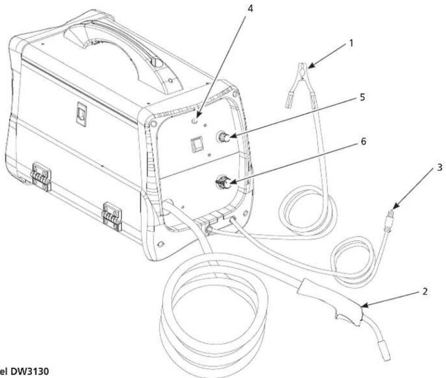
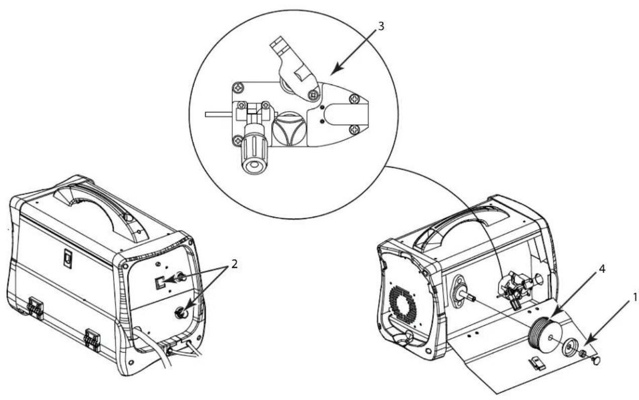
Figure 1 - Model DW3130
Components and Controls (Figure 1)
- Work Clamp – connects to work piece.
- Torch with .030 inch tip.
- Power Cord – plug into 120 volt outlet.
- Light – illuminates if thermostat has automatically shut welder off.
- Infinite Wire Speed Control – turn clockwise to increase wire speed and counterclockwise to decrease wire speed.
- Off/Heat Selector - Selects welding power and turns welder on. Four selections are possible: 1 - 2 - 3 - 4.
| HEAT SELECTOR | CIRCUIT BREAKER OR SLOW BLOW FUSE FOR 120V MODELS |
| 1-2-3 15 amp |  |
| 4 20 amp |  |
See page 17 for supply cable replacement instructions.
INSTALLATION INSTRUCTIONS
Location
Selecting the proper location can significantly increase performance, reliability and life of the arc welder.
- For best results locate welder in a clean and dry environment. Dust and dirt in the welder retain moisture and increase wear of moving parts.
- Place welder in an area with at least twelve inches (30,48 cm) of ventilation space at both the front and rear of unit. Keep all obstructions out of this ventilation space.
- Store welding wire in a clean, dry location with low humidity to prevent oxidation.
- Use a properly grounded receptacle for the welder and ensure welder is the only load on power supply circuit. Refer to chart on page 7 for correct circuit capacity.
- Use of an extension cord is not recommended for electric arc welding machines. Voltage drop in the extension cord may significantly degrade performance of the welder.
ASSEMBLY INSTRUCTIONS
WIRE INSTALLATION
NOTE: Before installing welding wire, be sure:
a. Diameter of welding wire matches groove in drive roller on wire feed mechanism (See Figure 2).
b. Wire matches contact tip in end of torch (See Figure 3).
A mismatch on any item could cause the wire to slip and/or bind.
NOTE: Always maintain control of loose end of welding wire to prevent unspooling.
- Verify unit is off and open door panel to expose wire feed mechanism.
- Remove the spool lock by pushing in and rotating 1/4 turn counterclockwise. Then remove lock, spring and retainer.
-
Flip tensioning knob down and swing arm up on drive mechanism. This allows initial feeding of wire into torch liner by hand.
-
Install wire spool onto spindle so wire can come off bottom of spool. Do not cut the wire loose yet. Install retainer, spring and lock by pushing in and turning lock 1/4 rotation clockwise.
-
Hold wire and cut the wire end from spool. Do not allow wire to unravel. Be sure end of wire is straight and free of burrs.
-
Feed wire through wire guide, over the groove in drive roller and into torch wire liner. Flip swing arm down and tension knob up. Adjust tension by rotating tension knob.
-
Unscrew nozzle and contact tip from end of welding torch (See Figure 3). Plug welder into a proper power supply receptacle.
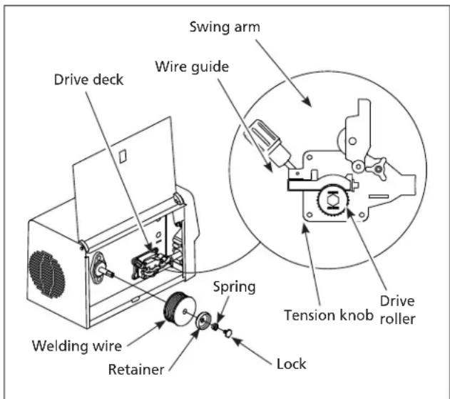
Figure 2 - Weld wire installation
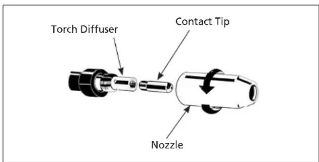
Figure 3 - Torch needle
| CONTACT TIP MARKINGS | |
| Mark Wire Size | |
| 0.6 mm | .024 inch |
| 0.8 mm | .030 inch |
| 0.9 mm | .035 inch |
- Turn on welder and set wire speed to 10. Activate torch trigger until wire feeds out past the torch end. Turn welder off.
- Carefully slip contact tip over wire, screw tip into torch end and reinstall nozzle (See Figure 3). Cut wire off approximately 1/4 inch from nozzle end.
Duty Cycle / Thermostatic Protection
Welder duty cycle is the percentage of actual weld time that can occur in a ten minute interval. For example, at a 20% duty cycle, actual welding can occur for two minutes, then the welder must cool for eight minutes.
Internal components of this welder are protected from overheating with an automatic thermal switch. An amber lamp is illuminated on the front panel if the duty cycle is exceeded. Do not switch unit off. This will allow the internal fan to cool the unit quickly. Welding operations may continue when the amber lamp is no longer illuminated.
Polarity
MIG welding wire requires the electrode to be positive.
Flux welding wire requires the electrode to be negative. Always use the polarity recommended by the welding wire manufacturer. The welder is factory set for flux welding wire.
TO CHANGE POLARITY (SEE FIGURE 4)
- Unplug power cord from socket.
- Open wire feed compartment door.
- Remove two nuts from polarity studs.
-
Connect cable from drive deck to positive stud and cable from work clamp to negative stud for electrode positive polarity for MIG welding. Connect cable from drive deck to negative stud and cable from work clamp to positive stud for electrode negative polarity for flux core welding.
-
Reinstall two nuts and tighten securely.

tightened properly,
excessive heat will be generated by the loose connection and the insulators on the studs will be damaged.
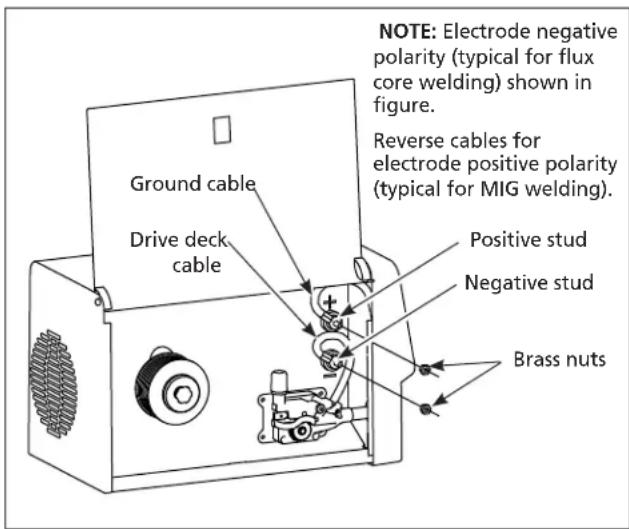
Figure 4 - Polarity control
Shielding Gas Preparation
DANGER and maintenance of compressed gas cylinders and regulators can result in serious injury or death! Always secure gas cylinders to a wall or other fixed support to prevent cylinder from falling over. Read, understand and follow all compressed gas and equipment warnings in the safety instructions.
NOTE: Shielding gas is not required if flux-core welding wire is used.
GAS TYPES
There are 3 types of gas generally used for gas metal arc welding; 100% argon, a mixture of 75% argon and 25% carbon dioxide (C25) or 100% carbon dioxide.

of gas recommended for your welder. Use ONLY an inert, non-flammable type of gas. Failure to do so will result in a very hazardous situation.
The 75/25 mixture is recommended for general steel welding. For aluminum welding, use 100% argon. Cylinders of either type gas may be obtained at your local welding supply outlet. Secure cylinder to prevent it from falling over.
ASSEMBLY INSTRUCTIONS (CONTINUED)
Obtaining Correct Gas Type. The gas used in any welding application for your welder must be an INERT, NON-FLAMMABLE TYPE. You can get the type of gas needed from a nearby welding gas distributor (often found in the yellow pages under "Welders" or "Welding Equipment").
REGULATOR
The regulator provides a constant shielding gas pressure and flow rate during the welding process. Each regulator is designed to be used with a specific gas or mixture of gases. The argon and argon mixture use the same thread type. The 100% carbon dioxide uses a different thread type. An adapter is available at your local welding gas supplier to change between the two.
HOSE AND REGULATOR HOOKUP PROCEDURE
WARNING under high pressure. Point cylinder outlet away from yourself and any bystanders before opening.
- With cylinder securely supported, stand on side of cylinder opposite cylinder outlet then remove cylinder cap and open valve slightly by turning counterclockwise. When gas is emitted from cylinder, close valve by turning clockwise. This will blow out dust or dirt that may have accumulated around valve seat.
- Install regulator onto cylinder valve. Tighten stem nut securely to gas valve.
- Install one end of gas hose to fitting on the back of welder and other end of hose to fitting on regulator. Make sure gas hose is not kinked or twisted.
- While standing opposite cylinder outlet, slowly open cylinder valve. Inspect for leaks in the connections.
- Remember to close gas cylinder valve when finished welding.
OPERATING INSTRUCTIONS
- Be sure to read, understand and comply with all precautions in the General Safety Instructions section. Be sure to read entire "Welding Guidelines" section before using this equipment.
- Turn welder off.
- Verify surfaces of metals to be joined are free from dirt, rust, paint, oil, scale or other contaminants. These contaminants make welding difficult and cause poor welds.
Warning this equipment or in the area while equipment is in use must wear protective welding gear including: eye protection with proper shade 10, flame resistant clothing, leather welding gloves and full foot protection.

WARNING or cutting galvanized, zinc plated, lead, or cadmium plated materials, refer to the General Safety Instructions Section for instructions. Extremely toxic fumes are created when these metals are heated.
- Connect work clamp to work piece or workbench (if metal). Make sure contact is secure. Avoid surfaces with paint, varnish, corrosion or non-metallic materials.
- Rotate Wire Speed Control to setting per decal inside wire feed compartment, then adjust as needed after test.
- Plug power cord into a proper voltage receptacle with proper circuit capacity (see circuit requirements on Page 6).
- Switch welder on to desired heat setting per decal inside wire feed compartment, then adjust as needed after test.
NOTE: These settings are general guidelines only. Heat setting may vary according to welding conditions and materials.
- Verify wire is extended 1/4 inch from contact tip. If not, squeeze trigger to feed additional wire, release trigger, turn welder off, and cut wire to proper length. Then, switch back on to desired heat setting.
- Position torch near work piece, lower welding helmet by nodding head or positioning the hand shield, and squeeze torch trigger. Adjust heat setting and wire speed as needed.
- When finished welding, turn welder off and store properly.
General
The DW3130 can utilize the Flux Cored Arc Welding (FCAW) process or the Gas Metal Arc Welding (GMAW) process. The weld must be protected (shielded) from contaminants in the air while it is molten. The FCAW process uses a tubular wire with a flux material inside. The flux creates a shielding gas when melted. The GMAW process uses inert gas to shield the weld while molten.
When current is produced by a transformer (welding machine) and flows through the circuit to the weld wire, an arc is formed between the end of the weld wire and the work piece. This arc melts the wire and the work piece. The melted metal of the weld wire flows into the molten crater and forms a bond with the work piece as shown (Figure 5).
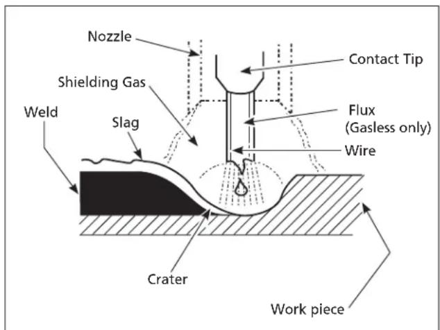
Figure 5 - Weld Components
Arc Welding Basics
Six basic techniques affect weld quality. These are: wire selection, heat setting, weld angle, wire speed, travel speed, and electrode extension. An understanding of these techniques is necessary for effective welds.
HEAT SETTING
The correct heat involves the adjustment of the welding machine to the required setting. Heat or voltage is regulated by a switch on the welder. The heat setting used depends on the size (diameter) and type of wire, position of the weld, and the thickness of the work piece. Consult specifications listed on the welder. It is suggested that the welder practice with scrap metal to adjust settings, and compare welds with Figure 7.
WIRE TYPE AND SIZE
The correct choice of wire type involves a variety of factors, such as welding position, work piece material type, thickness, and condition of surface to be welded. The American Welding Society, AWS, has set up certain requirements for each type of wire.
FLUX-CORED WIRE
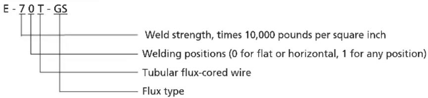
AWS E71T-GS or E71T-11 is recommended for this welder.
SOLID WIRE
ER-70S6 is recommended for this welder.
WELDING GUIDELINES (CONTINUED)
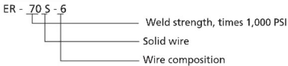
Weld Angle
Weld angle is the angle at which the nozzle is held during the welding process. Using the correct angle ensures proper penetration and bead formation. As different welding positions and weld joints become necessary, nozzle angle becomes an increasingly important factor in obtaining a satisfactory weld. Weld angle involves two positions - travel angle and work angle.
TRAVEL ANGLE is the angle in the line of welding and may vary from 5° to 45° from the vertical, depending on welding conditions.
WORK ANGLE is the angle from horizontal, measured at right angles to the line of welding.
For most applications, a 45° travel angle and 45° work angle is sufficient. For specific applications, consult an arc welding handbook.
Wire speed
The wire speed is controlled by the knob on the front panel. The speed needs to be "tuned" to the rate at which the wire is being melted in the arc. Tuning is one of the most critical functions of wire feed welding. Tuning should be performed on a scrap piece of metal the same type and thickness as that to be welded. Begin welding with one hand "dragging" the torch nozzle across the scrap piece while adjusting the wire speed with the other hand. Too slow of speed will cause sputtering and the wire will burn up into the contact tip. Too fast a speed will also cause a sputtering sound and the wire will push into the plate before melting. A smooth buzzing sound indicates the wire speed is properly tuned. Repeat the tuning procedure each time there is a change in heat setting, wire diameter or type, or work piece material type or thickness. For Aluminum, wire speed is typically set higher (7-9 speed range).
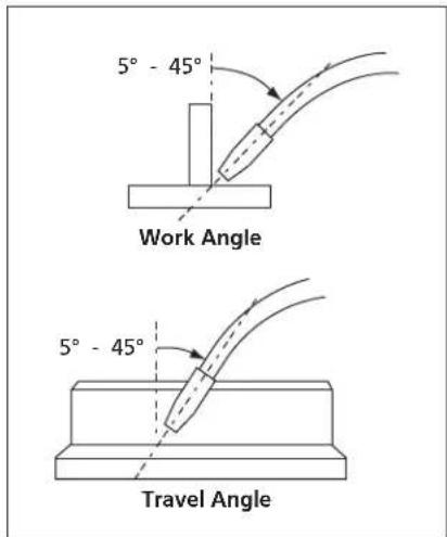
Figure 6 - Weld Angle
Figure 7 - Weld Appearance
Travel Speed
The travel speed is the rate at which the torch is moved across the weld area. Factors such as diameter and type of weld wire, amperage, position, and work piece material thickness all affect the speed of travel necessary for completing a good weld (See Figure 7). When the speed is too fast, the bead is narrow and bead ripples are pointed as shown. When the speed is too slow, the weld metal piles up and the bead is high and wide. For Aluminum, travel speed is typically faster.
Electrode Extension
Electrode extension (or electrode stick-out) is the distance between the end of the contact tip and the end of the welding wire. The recommended electrode extension is from 1/4 to 1/2 in (6 to 13 mm). If the electrode extension is too long, welding current will be reduced and the bead will be high and narrow with less penetration.
Slag Removal (Flux-Cored Wire Only)
Western Windows warning and safety glasses (ANSI Standard Z87.1) and protective clothing when removing slag. Hot, flying debris can cause personal injury to anyone in the area.
After completing the weld, wait for the welded sections to cool. A protective coating called slag now covers the weld bead which prevents contaminants in the air from reacting with the molten metal. Once the weld cools to the point that it is no longer glowing red, the slag can be removed. Removal is done with a chipping hammer. Lightly tap the slag with the hammer and break it loose from the weld bead. The final clean-up is done with a wire brush. When making multiple weld passes, remove the slag before each pass.
Welding Positions
Four basic welding positions can be used; flat, horizontal, vertical, and overhead. Welding in the flat position is easier than any of the others because welding speed can be increased, the molten metal has less tendency to run, better penetration can be achieved, and the work is less fatiguing. Welding is performed with the wire at a 45^ travel angle and 45^ work angle.
Other positions require different techniques such as a weaving pass, circular pass, and jogging. A higher skill level is required to complete these welds.
Overhead welding is the least desirable position as it is the most difficult and dangerous. Heat setting and wire selection will vary depending upon the position.
All work should be performed in the flat position if possible. For specific applications, consult an arc welding technical manual.
Weld Passes
Sometimes more than one pass is necessary to fill the joint. The root pass is first, followed by filler passes and the cover pass. If the pieces are thick, it may be necessary to bevel the edges that are joined at a 60° angle. Remember to remove the slag before each pass for the FCAW process.
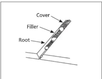
Figure 8 - Weld Passes
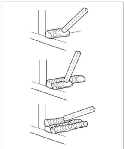
natural_image
Three-step diagram showing a tool interacting with a wooden post, no text or symbols presentFigure 9 - Multiple Weld Passes
WELDING GUIDELINES (CONTINUED)
Push vs Pull Technique
The type and thickness of the work piece dictates which way to point the torch nozzle. For thin materials (18 gauge and smaller) and all aluminum, the nozzle should point out in front of the weld puddle and push the puddle across the workpiece. For thicker steel, the nozzle should point into the puddle to increase weld penetration. This is called backhand or pull technique (See Figure 10).
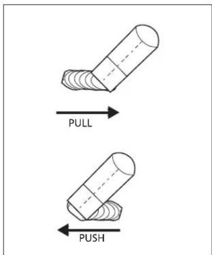
Figure 10
NOTES
GEITING STARTED
SPECIFICATIONS
INSTALLATION
TOUBLUESHOOTINGQPER
REPAIR
MAINTENANCE
i
TROUBLESHOOTING GUIDE
SYMPTOM POSSIBLE CAUSE(S) CORRECTIVE ACTION
| No output 1. Duty cycle exceeded 1. Allow welder to cool until lamp goes out. | ||
| 2. Poor work clamp connection 2. Be sure all connections are secure, and attaching surface is clean. | ||
| 3. Blown breaker or fuse 3. Reduce circuit load, reset breaker or replace fuse. | ||
| Wire tangles at drive roller 1. Wrong size contact tip 1. Use proper size contact tip. | ||
| 2. Torch liner clogged or damaged 2. Clean or replace wire liner. | ||
| 3. Contact tip clogged or damaged 3. Clean or replace contact tip. | ||
| 4. Drive roller worn 4. Replace. | ||
| 5. Not enough tension 5. Tighten tension knob. | ||
| Gun nozzle arcs to work surface | 1. Slag inside gun nozzle | 1. Clean slag from gun nozzle. |
| 2. Insulation ring melted/expired | 2. Replace nozzle. | |
| Work clamp and/or cable gets hot | 1. Poor contact | 1. Be sure all connections are secure, and attaching surface is clean. |
| 2. Using an extension cord with excessive length | 2. Never use an extension cord longer than 20 ft. | |
| Wire does not feed | 1. Wire jammed | 1. Reload wire. |
| 2. Out of wire | 2. Replace wire spool. | |
| 3. Not enough tension 3. Tighten tension knob if wire is slipping. | ||
| 4. Wire liner worn | 4. Replace liner. | |
| 5. Wire disconnected internally 5. Visit www.campbellhausfeld.com | ||
| 6. Contact tip clogged | 6. Replace contact tip. | |
| (Aluminum) Wire burns back into tip or (Aluminum) Metal bubbles or burns through | 1. Wire speed too slow | 1. Run speed in 7 - 10 range. |
| 2. Travel speed too slow or heat is too high | 2. Increase the travel speed or reduce heat settings. | |
| Weld pops and sputters | 1. Wire speed setting | 1. Tune in correct setting (1-5 mild steel; 5-10 aluminum). |
| 2. Contact tip size too large | 2. Replace contact tip. | |
| 3. Polarity set incorrectly 3. Reverse polarity. | ||
| 4. Drive roller slipping | 4. Increase tension. | |
| 5. Gas bottle empty | 5. Replace gas bottle. | |
| Bead is intermittently too thin | 1. Inconsistent travel speed | 1. Decrease and maintain constant travel speed. |
| 2. Output heat setting too low | 2. Increase output heat setting. | |
| Bead is intermittently too thick | 1. Slow and/or inconsistent travel speed | 1. Increase and maintain travel speed. |
| 2. Output heat setting too high | 2. Reduce output heat setting. | |
| Ragged depressions at edge of weld | 1. Travel speed too fast | 1. Decrease travel speed. |
| 2. Wire speed too fast | 2. Decrease wire speed. | |
| 3. Output heat setting too high | 3. Reduce output heat setting. | |
| Weld bead does not penetrate base metal | 1. Inconsistent travel speed | 1. Decrease and maintain constant travel speed. |
| 2. Output heat setting too low | 2. Increase output heat setting. | |
| 3. No or low shielding gas | 3. Use gas for MIG process or refill bottle. | |
| 4. Wrong shielding gas (aluminum) | 4. Use only 100% Argon gas. | |
| 5. Extension cord is too long | 5. Never use an extension cord longer than 20 ft. | |
| 6. (Aluminum) Possible oxide buid-up on surface | 6. Clean surface thoroughly with a stainless steel brush only. | |
| Wire sputters and sticks | 1. Damp wire | 1. Use dry wire and store in dry location. |
| 2. Wire speed too fast | 2. Reduce wire speed. | |
| 3. Wrong type of wire | 3. Use flux-cored wire when not using gas. | |
| 4. No or low shielding gas | 4. Use gas for MIG process or refill bottle. | |
MAINTENANCE
DisWARNING supply and turn machine off before inspecting or servicing any components. Keep wire compartment cover closed at all times unless wire needs to be changed.
Before Every Use:
-
Check condition of weld cables and immediately repair or replace any cables with damaged insulation.
-
Check condition of power cord and immediately repair or replace any cord if damaged.
-
Inspect the condition of the torch contact tip and nozzle. Remove any weld slag. Replace torch contact tip or nozzle if damaged.
Do WARNING is welding machine with cracked or missing insulation on welding cables, torch or power cord.
Every 3 Months:
- Replace any unreadable safety labels on the welder.
- Use compressed air to blow all dust and lint from ventilation openings.
- Clean wire groove on drive roller. Remove drive roller and use a small wire brush to clean. Replace if worn or damaged.
Consumable and Wear Parts
The following parts require replacement:
- Wire feed drive roller
- Torch liner
- Nozzle/contact tips
- Wire - This welder will accept either 4 inch or 8 inch diameter spools. Flux-Cored welding wire is susceptible to moisture and oxidizes over time, so it is important to select a spool size that will be used within approximately 6 months. For mild steel welding, AWS ER70S6 solid wire or AWS E71T-GS Flux-Cored wire is recommended.
SUPPLY CABLE REPLACEMENT
| 1. Verify that welder is OFF and power cord disconnected. |
| 2. Remove welder side panel to expose switches. |
| 3. Disconnect the power cord leads per the diagram inside the unit. |
| 4. Disconnect the ground wire connected to welder base. |
| 5. Loosen the cord strain relief screws and pull cord out of strain relief. |
| 6. Install new cord in reverse order per the diagram inside the unit. |
Changing Wire Sizes
This welder is setup for .030 inch (0.8 mm) wire. If a different wire size is used, the wire feed drive roller and contact tip may need changing. There are two grooves in the drive roller. The small groove is for .024 inch (0.6 mm) MIG wire and the large groove is for .030 inch - .035 inch (0.8 mm - 0.9 mm) flux core and MIG wire. Rotate the tension knob down and swing arm up. Remove roller support by removing two screws and flip the drive roller to choose the correct groove. The contact tip should also match the wire diameter used. The tip diameter is marked on the contact tip in inches and/or millimeters.
REPAIR PARTS ILLUSTRATION FOR DW3130
For Repair Parts, visit www.campbellhausfeld.com
24 hours a day - 365 days a year
Please provide following information:
- Model number
- Serial number (if any)
- Part description and number as shown in parts list
REPAIR PARTS LIST FOR DW3130
Ref.
No. Description Part Number:
| 1 SPOOL SPINDLE KIT: INCLUDES KNOB, WASHER, SPOOL TENSIONER SPRING AND SPOOL LOCKING KNOB | DW313011AV |
| 2 KNOB/SWITCH KIT: INCLUDES ON/OFF SWITCH, POWER LEVEL KNOB,POTENTIOMETER, VOLTAGE SWITCH AND WIRE SPEED KNOB | DW313012AV |
| 3 WIRE FEED KIT: INCLUDES WIRE FEED UNIT, WIRE FEED ROLLER DW313013AV | |
| 4 SAMPLE SPOOL AND TIPS KIT: INCLUDES SAMPLE WIRE SPOOL (0.8MM), CONTACT TIPS AND HEX WRENCH | DW313014AV |
| 5 HOSE AND CLAMP KIT: INCLUDES AIR HOSE AND CLAMPS DW313015AV |
Reminder: Keep your dated proof of purchase for warranty purposes! Attach it to this manual or file it for safekeeping.
LIMITED WARRANTY
- Duration: The manufacturer warrants that it will repair, at no charge for parts or labor, the Welder, Welding Gun, or Cables, proven defective in material or workmanship, during the following time period(s) after date of original retail purchase:
- For 5 Years: The Welder Transformer and Rectifier (as applicable)
- For 90 Days: The Welding Clamps, MIG Gun, Electrode Holder, Accessories, and Welding Cables (as applicable)
- Who Gives This Warranty (Warrantor): Campbell Hausfeld a Marmon/Berkshire Hathaway Company, 100 Production Drive, Harrison, Ohio, 45030. Visit: www.campbellhausfeld.com.
- Who Receives This Warranty (Purchaser): The original purchaser of the Campbell Hausfeld product.
- What is covered under this warranty: Defects in material and workmanship which occur within the duration of the warranty period. This warranty extends to the Welder, the Welders Transformer and Rectifier, Welding Gun or Electrode Holder, and cables only.
- What is not covered under this warranty:
A. Implied warranties, including those of merchantability and FITNESS FOR A PARTICULAR PURPOSE ARE LIMITED IN DURATION TO THIS EXPRESS WARRANTY. After this period, all risks of loss, from whatever reason, shall be on the purchaser. Some states do not allow limitations on how long an implied warranty lasts, so above limitations may not apply to you.
B. ANY INCIDENTAL, INDIRECT, OR CONSEQUENTIAL LOSS, DAMAGE, OR EXPENSE THAT MAY RESULT FROM ANY DEFECT FAILURE OR MALFUNCTION OF THE CAMPBELL HAUSFELD PRODUCT. Some states do not allow limitations on how long an implied warranty lasts, so above limitations may not apply to you.
C. This warranty does not apply to any accessory items included with the product which are subject to wear from usage; the repair or replacement of these items shall be at the expense of the owner. These MIG items include but are not limited to; Contact Tips, Nozzles, Gun Liners, Drive Rollers, Felt Wire Cleaner. In addition, this warranty does not extend to any damage caused by the untimely replacement or maintenance of any of the previously listed CONSUMABLE parts.
D. Any failure that results from accident, purchaser's abuse, neglect or failure to operate products in accordance with instructions provided in the owner's manual(s) supplied with the product.
E. Pre-delivery service, i.e. assembly and adjustment.
-
Responsibilities of Warrantor under this warranty: Repair or replace, at Warrantor's option, products or components which have failed within duration of the warranty period.
-
Responsibilities of purchaser under this warranty:
A. Visit www.campbellhausfeld.com for warranty assistance.
B. Provide dated proof of purchase and maintenance records.
C. All welders must be delivered or shipped to the nearest Campbell Hausfeld Authorized Service Center. Freight costs, if any, must be borne by the purchaser.
D. Use reasonable care in the operation and maintenance of the products as described in the owner's manual(s).
- When Warrantor will perform repair or replacement under this warranty: Repair or replacement will be scheduled and serviced according to the normal work flow at the servicing location, and depending on the availability of replacement parts.
This Limited Warranty gives you specific legal rights and you may also have other rights which vary from state to state.
NOTES
GEITING STARTED
SPECIFICATIONS
INSTALLATION
natural_image
Line drawing of a portable electronic device with coiled cable and connectors (no text or symbols)Modèle: DW3130
CH CAMPBELL HAUSFELD.
OSHA 29 CFR 1910, du Superintendent of Documents, U.S. Government Printing Office, Washington, D.C. 20402
Norme CSA W117.2, de l'Association Canadian Standards Association, Standards Sales, 178 Rexdale Boulevard, Rexdale, Ontario, Canada M9W 1R3
Norme NFPA 51B, le l'Association National Fire Protection Association, Batterymarch Park, Quincy, MA 02269
natural_image
Three-step diagram showing a tool interacting with a wooden post, no text or symbols presentFigure 9 - Passes multiples
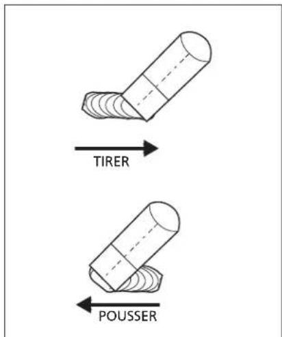
Figure 10
NOTES
GUIDE DE DÉPANNAGE
natural_image
Line drawing of a portable electronic device with coiled cables and connectors (no text or symbols)Modelo: DW3130

CAMPBELL HAUSFELD.
Harrison, Ohio 45030
¡REGISTRE SU PRODUCTO EN LÍNEA AHORA MISMO! www.campbellhausfeld.com/reg LEA Y SIGA TODAS LAS INSTRUCCIONES • GUARDE ESTAS INSTRUCCIONES • NO LAS DESECHE

/CampbellHausfeld

CHcompressors

CHcompressors

@CHCompressors

CHcompressors

CampbellHausfeld
ANTES DE COMENZAR
Descripción
OSHA 29 CFR 1910, del Superintendent of Documents, U.S. Government Printing Office, Washington, D.C. 20402
Norma NFPA 70, de National Fire Protection Association, Batterymarch Park, Quincy, MA 02269
Norma CSA W117.2, de Canadian Standards Association, Standards Sales, 178 Rexdale Boulevard, Rexdale, Ontario, Canada M9W 1R3
Norma NFPA 51B, de National Fire Protection Association, Batterymarch Park, Quincy, MA 02269
Norma ANSI Z87.1, del American National Standards Institute, 1430 Broadway, New York, NY 10018
Figura 1 - Modelo DW3130
Componentes y controles (figura 1)
natural_image
Three-step diagram showing a tool interacting with a wooden log, no text or symbols presentPara repuestos, visite www.campbellhausfeld.com


- CH CAMPBELL HAUSFELD®
- Wire Feed Arc Welder
- CH CAMPBELL HAUSFELD.
- CampbellHausfeld
- BEFORE YOU BEGIN
- Description
- UNPACKING
- POWNTING
- Required Items - Not Included
- GENERAL SAFETY INSTRUCTIONS
- Safety Guidelines
- △ DANGER
- Warning
- CAUTION
- NOTICE
- Safety Symbols
- GENERAL SAFETY INSTRUCTIONS (CONTINUED)
- California Proposition 65
- Illinois Lead Poisoning Prevention Act
- Circuit Requirements
- Important Safety Information
- General Safety
- DANGER
- Additional Safety Standards
- SAVE THESE INSTRUCTIONS DO NOT DISCARD
- GLOSSARY OF WELDING TERMS
- GETTING TO KNOW YOUR UNIT
- Components and Controls (Figure 1)
- INSTALLATION INSTRUCTIONS
- Location
- ASSEMBLY INSTRUCTIONS
- WIRE INSTALLATION
- Duty Cycle / Thermostatic Protection
- Polarity
- TO CHANGE POLARITY (SEE FIGURE 4)
- Shielding Gas Preparation
- GAS TYPES
- ASSEMBLY INSTRUCTIONS (CONTINUED)
- REGULATOR
- HOSE AND REGULATOR HOOKUP PROCEDURE
- OPERATING INSTRUCTIONS
- General
- Arc Welding Basics
- HEAT SETTING
- WIRE TYPE AND SIZE
- WELDING GUIDELINES (CONTINUED)
- Weld Angle
- Wire speed
- Travel Speed
- Electrode Extension
- Slag Removal (Flux-Cored Wire Only)
- Welding Positions
- Weld Passes
- Push vs Pull Technique
- NOTES
- TROUBLESHOOTING GUIDE
- MAINTENANCE
- Before Every Use:
- Every 3 Months:
- Consumable and Wear Parts
- Changing Wire Sizes
- REPAIR PARTS ILLUSTRATION FOR DW3130
- For Repair Parts, visit www.campbellhausfeld.com
- hours a day - 365 days a year
- REPAIR PARTS LIST FOR DW3130
- LIMITED WARRANTY
- CAMPBELL HAUSFELD.
- ANTES DE COMENZAR
- Descripción
- Componentes y controles (figura 1)
- Para repuestos, visite www.campbellhausfeld.com
Brand : Campbell Hausfeld
Model : DW313000
Category : Welding machine