
WS099001AV - Welding machine Campbell Hausfeld - Free user manual and instructions
Find the device manual for free WS099001AV Campbell Hausfeld in PDF.

| Product Type | Shielded Metal Arc Welding (SMAW) Machine |
| Brand | Campbell Hausfeld |
| Model | WS099001AV |
| Power Supply Voltage | 115 V AC |
| Recommended Circuit Current | 15 A or 20 A (dedicated circuit) |
| Amperage Range | Infinite adjustment, approximately 35-100 A depending on settings |
| Recommended Electrode Diameters | 1.6 mm (1/16 in) for 15 A; 1.98 mm (5/64 in) for 20 A |
| Maximum Weld Thickness (single pass) | 3.2 mm (1/8 in) in mild steel |
| Thermal Protection | Thermostat with indicator light (model WS090001) or integrated into switch |
| Switch | On/Off; some models have Low/Off/High selector |
| Included Accessories | Electrode holder, ground clamp, welding cables (2 x 1.8 m), hand shield (except model WS1020) |
| Cable Length | 1.8 m (6 ft) each, power cord 1.8 m (6 ft) |
| Power Cord Type | 14-2 AWG or 14-3 AWG per model |
| Main Functions | Shielded metal arc welding; amperage adjustment; thermal protection |
| Maintenance | Check cable insulation, clean ventilation openings with compressed air, replace illegible labels |
| Safety | Wear mask with filter #10 minimum, leather gloves, fire-resistant clothing; work in dry, well-ventilated area; keep fire extinguisher within reach |
| Available Spare Parts | Electrode holder, ground clamp, switch, handwheel, cables, etc. (see parts list in manual) |
| Warranty | 5 years on transformer and rectifier, 3 years on the whole unit (excluding accessories), 1 year on cables and clamps |
| Estimated Weight | Approximately 15-20 kg (not specified in manual, estimate for a welder of this class) |
Frequently Asked Questions - WS099001AV Campbell Hausfeld
User questions about WS099001AV Campbell Hausfeld
0 question about this device. Answer the ones you know or ask your own.
Ask a new question about this device
Download the instructions for your Welding machine in PDF format for free! Find your manual WS099001AV - Campbell Hausfeld and take your electronic device back in hand. On this page are published all the documents necessary for the use of your device. WS099001AV by Campbell Hausfeld.
USER MANUAL WS099001AV Campbell Hausfeld
Please read and save these instructions. Read carefully before attempting to assemble, install, operate or maintain the product described. Protect yourself and others by observing all safety information. Failure to comply with instructions could result in personal injury and/or property damage! Retain instructions for future reference.

CAMPBELL HAUSFELD™
BUILT TO LAST
Shielded Metal
Arc Welder

Description
This line of Campbell Hausfeld Arc Welders is designed to be used on standard 115V household current. These welders are equipped with amperage control to accurately select the proper current needed for various welding conditions. Internal components are thermostatically protected.
This welder can weld up to 1/8" steel in a single pass. Recommended electrode size is 1/16" diameter for 15 amp circuits, up to 5/64" diameter for 20 amp circuits. For replacement electrodes, call (800) 746-5641 for the nearest dealer.
Unpacking
When unpacking, inspect carefully for any damage that may have occurred during transit. Report any damaged or missing items by calling 1-800-746-5641.
Circuit Requirements
▲ CAUTION
This equipment requires a dedicated
115 volt circuit. Refer to the following chart for the correct circuit breaker or fuse rating. Do not run other appliances, lights, or tools on this circuit while operating this equipment. Extension cords are not recommended. Blown fuses or tripped circuit breakers can result from failure to comply with this recommendation.
Electrode Circuit Breaker or Diameter Slow Blow Fuse
| 1/16 15 amp | |
| 5/64 20 amp |
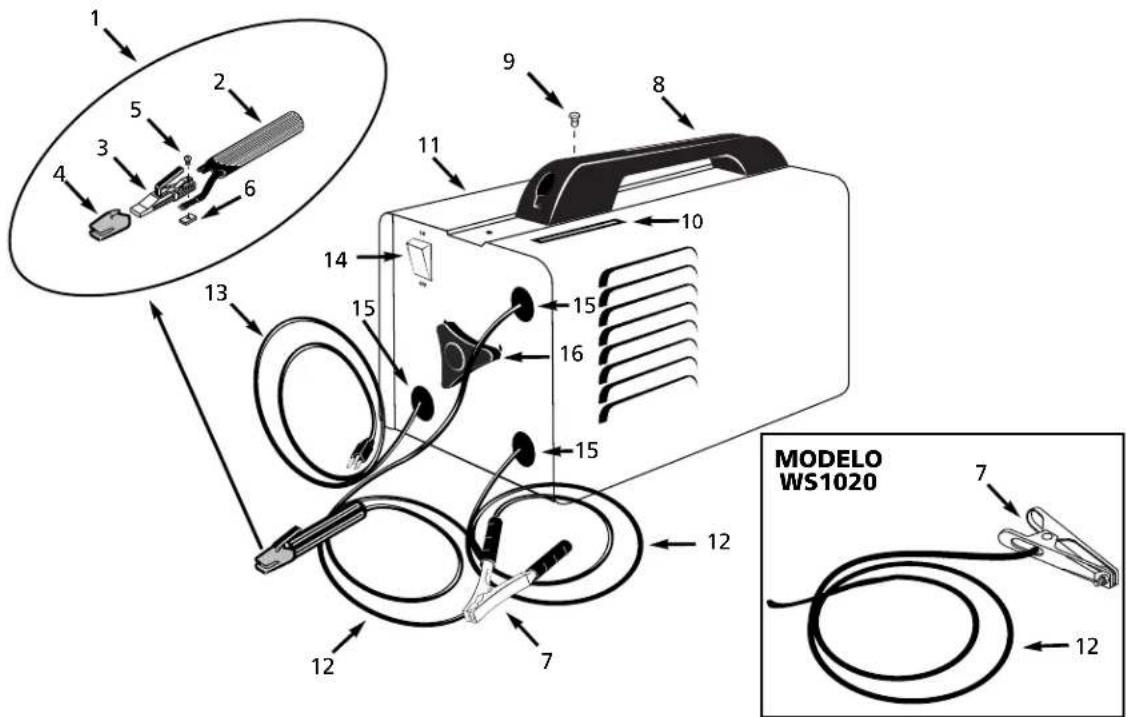
Components and Controls
- Work Clamp - connect to work piece
- Electrode Holder - holds electrode welding rod
- Power Cord - plug into 115 volt outlet.
- On/Off Switch - lights if thermostat has automatically shut unit off.
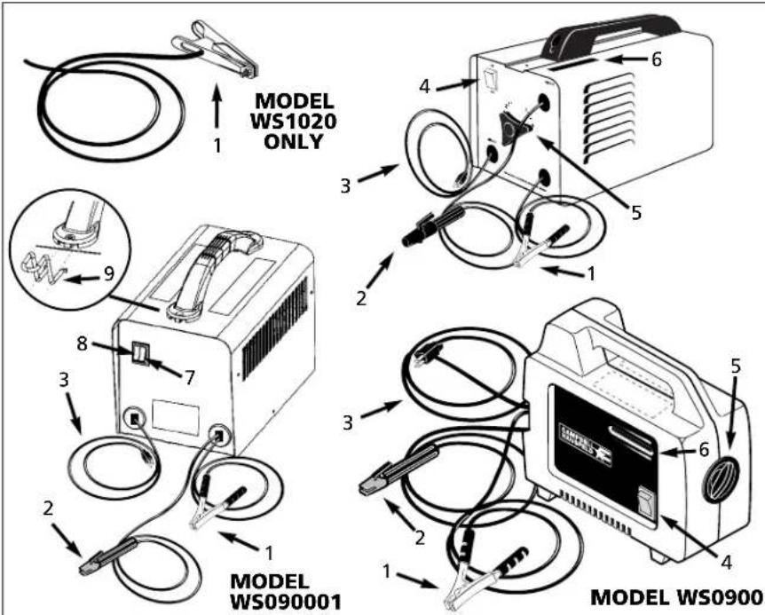
Figure 1 - Welder Components and Controls
- Infinite Amperage Control Knob - turns clockwise to increase amperage and counterclockwise to decrease amperage.
- Welding Amp Indicator - as the amperage control knob (5) is rotated, the amperage indicator moves displaying approximate weld amps.
- Low/Off/High Automatic Amperage Adjustment Switch - low position for 1/16" rods and high position for 5/64" rods. WS090001 Model only.
- Thermostat light - light activates if thermostat has automatically shut unit off. WS090001 Model only.
- Cable storage clips - for safer storage of welding cables. WS090001 Model only.
General Safety
DANGER
Danger means a hazard that will
cause death or serious injury if the warning is ignored.
▲WARNING
Warning means a hazard that could
cause death or serious injury if the warning is ignored.
▲ CAUTION
Caution means a hazard that may
cause minor or moderate injury if the warning is ignored. It also may mean a hazard that will only cause damage to property.
NOTE: Note means any additional information pertaining to the product or its proper usage.
General Safety (Con't)
▲WARNING
Always keep a fire extinguisher accessible while performing arc welding operations.

- Before starting or servicing any electric arc welder, read and understand all instructions. Failure to follow safety precautions or instructions can cause equipment damage and or serious personal injury or death.
- All installation, maintenance, repair and operation of this equipment should be performed by qualified persons only in accordance with national, state, and local codes.
▲WARNING
Improper use of electric arc welders can cause electric shock, injury, and death! Take all precautions described in this manual to reduce the electric shock.
- Verify that all components of the arc welder are clean and in good condition prior to operating the welder. Be sure that the insulation on all cables, electrode holders, and power cords is not damaged. Always repair or replace damaged components before operating the welder. Always keep welder panels, shields, etc. in place when operating the welder.
- Always wear dry protective clothing and welding gloves, and insulated footwear.
- Always operate the welder in a clean, dry, well ventilated area. Do not operate the welder in humid, wet, rainy, or poorly ventilated areas.
- Be sure that the work piece is properly supported and grounded prior to beginning any electric arc welding operation.
- Coiled welding cable should be spread out before use to avoid overheating and damage to insulation.
DANGER
Never immerse the electrode or
electrode holder in water. If the welder becomes wet for any reason, be absolutely certain that it is completely clean and dry prior to attempting use!
- Always shut the equipment off and unplug the power prior to moving the unit.
• Always attach the work lead first.
- Verify that the work piece is securely grounded.
- Always shut off electric arc welding equipment when not in use and remove the electrode from the holder.
- Never allow any part of the body to touch the electrode and ground or grounded work piece at the same time.
- Awkward welding conditions and positions can be electrically hazardous. When crouching, kneeling or at elevations, be sure to insulate all conductive parts, wear appropriate protective clothing, and take precautions to prevent injury from falls.
- Never attempt to use this equipment at current settings or duty cycles higher than those specified on the equipment labels.
- Never use an electric arc welder to thaw frozen pipes.
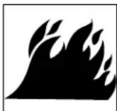
WARNING
Flying sparks and hot metal can cause injury. As welds cool, slag can be thrown off. Take all precautions described in this manual to reduce the possibility of injury from flying sparks and hot metal.
- Wear ANSI approved face shield or safety glasses with side shield protection when chipping or grinding metal parts.
- Wear ear plugs when welding overhead to prevent spatter or slag from falling into ears.
▲WARNING
Electric arc welding operations produce intense light and heat and ultraviolet (UV) rays. This intense light and UV rays can cause injury to eyes and skin. Take all precautions described in this manual to reduce the possibility of injury to eyes and skin.
- All persons operating this equipment or in the area while equipment is in use must wear protective welding gear including: welding helmet or shield with at least shade 10, flame resistant clothing, leather welding gloves, and full foot protection.
▲WARNING
Never look at arc
welding operations
without eye protection as described above. Never use a shade filter lens that is cracked, broken, or rated below number 10. Warn others in the area not to look at the arc.
▲WARNING
Electric arc welding operations cause sparks and heat metal to temperatures that can cause severe burns! Use protective gloves and clperforming any metal w operation. Take all preca described in this manual possibility of skin and cl
- Make sure that all persons in the welding area are protected from heat, sparks, and ultraviolet rays. Use additional face shields and flame resistant barriers as needed.
- Never touch work pieces until completely cooled.
▲WARNING
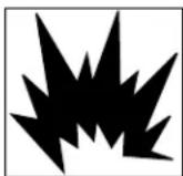
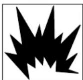
Heat and sparks produced during electric arc welding and other metal working operations can ignite flammable and explosive. Take all precautions desc manual to reduce the po-flames and explosions.
- Remove all flammable materials within 35 feet (10.7 meters) of welding arc. If removal is not possible, tightly cover flammable materials with fire proof covers.
- Do not operate any electric arc welder in areas where flammable or explosive vapors may be present.
- Take precautions to be sure that flying sparks and heat do not cause flames in hidden areas, cracks, behind bulkheads, etc.
▲WARNING
Fire hazard! Do not weld on containers or pipes that contain or have contained flammable materials of gaseous or liquid com
▲WARNING
Arc welding closed cylinders or containers such as tanks or drums can cause explosion if not properly vented!
Verify that any cylinder or container to be welded has an adequate ventilation hole, so that expanding gases can be released.
General Safety (Con't)
▲WARNING
Do not breathe fumes that are produced by the arc welding operation. These fumes
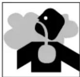
are dangerous. If the welding area cannot be adequately ventilated, be sure to use an air-supplied respirator.
- Keep the head and face out of the welding fumes.
- Do not perform electric arc welding operations on metals that are galvanized or cadmium plated, or contain zinc, mercury, or beryllium without completing the following precautions:
a. Remove the coating from the base metal.
b. Make sure that the welding area is well ventilated.
c. Use an air-supplied respirator.
Extremely toxic fumes are created when these metals are heated.
▲WARNING
The electromagnetic field that is generated during arc welding may interfere with the operation of various
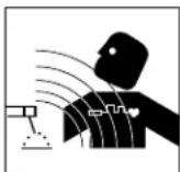
electrical and electronic devices such as cardiac pacemakers. Persons using such devices should consult with their physician prior to performing any electric arc welding operations.
- Route the electrode and work cables together and secure with tape when possible.
- Never wrap arc welder cables around the body.
- Always position the electrode and work leads so that they are on the same side of the body.
- Exposure to electromagnetic fields during welding may have other health effects which are not known.
⚠ WARNING
Always be sure that the welding
area is secure and free of hazards (sparks, flames, glowing metal or slag) prior to leaving. Be sure that equipment is turned off and electrode is removed. Be sure that cables are loosely coiled and out of the way. Be sure that all metal and slag has cooled.
ADDITIONAL SAFETY STANDARDS
ANSI Standard Z49.1 from American Welding Society, 550 N.W. LeJune Rd. Miami, FL 33126
Safety and Health Standards
OSHA 29 CFR 1910, from Superintendent of Documents, U.S. Government Printing Office, Washington, D.C. 20402
National Electrical Code
NFPA Standard 70, from National Fire Protection Association, Batterymarch Park, Quincy, MA 02269
Safe Handling of Compressed Gases in Cylinders
CGA Pamphlet P-1, from Compressed Gas Association, 1235 Jefferson Davis Highway, Suite 501, Arlington, VA 22202
Code for Safety in Welding and Cutting
CSA Standard W117.2, from Canadian Standards Association, Standards Sales, 178 Rexdale Boulevard, Rexdale, Ontario, Canada M9W 1R3
Cutting And Welding Processes
NFPA Standard 51B, from National Fire Protection Association, Batterymarch Park, Quicy, MA 02269
Safe Practices For Occupational And Educational Eye And Face Protection
ANSI Standard Z87.1, from American National Standards Institute, 1430 Broadway, New York, NY 10018 Refer to the Material Safety Data Sheets and the manufacturers instructions for metals, electrodes, coatings and cleaners.
Installation
Location
Selecting the proper location can significantly increase performance, reliability and life of the arc welder.
- For best results locate the welder in an environment that is clean and dry. Dust and dirt in the welder retain moisture and increase wear of moving parts.
- Store electrodes in a clean, dry location with low humidity to preserve the flux coating.
- The receptacle used for the welder must be properly grounded and the welder must be the only load on the power supply circuit. Refer to the Circuit Amps chart on page 1 for correct circuit capacity.
- The use of an extension cord is not recommended for arc welding machines. Extension cord use will significantly degrade the performance of the welder.
Assembly
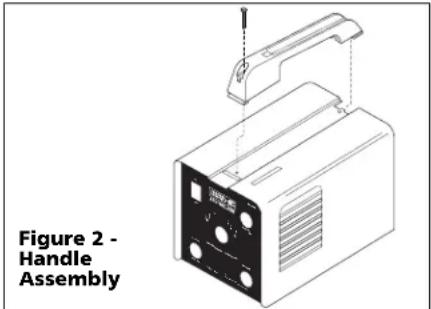
HANDLE ASSEMBLY-MODELS WS0950, WS1000 AND WS1020 ONLY
-
Slide handle in slot toward rear of unit.
-
Push forward and snap front of handle in cutout in cabinet.
-
Fasten screw through handle and into cabinet (See Figure 2).
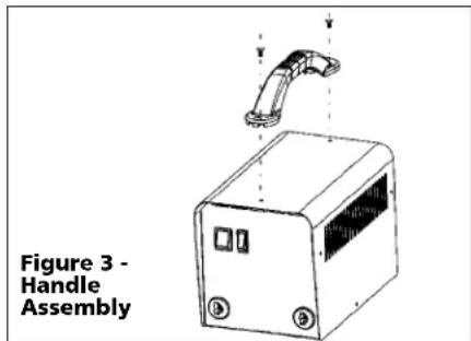
HANDLE ASSEMBLY- MODEL WS090001 ONLY
- Align the end holes on the handle with the holes on top of the welder, then secure with screws (Figure 3).
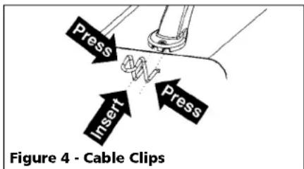
- Insert cable clips by pressing inward on sides of clip and pushing into the slots on front of handle as shown in Figure 4. Repeat for opposite side of handle.
WORK CLAMP (WS0900, 950, 1000 AND 1020)
- Loosen hex bolt or nut on work clamp.
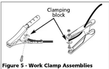
- Insert either cable from the welder through the clamp handle and slide
Assembly (Con't)
bare wire under the clamp block. Tighten hex bolt or nut making sure bare wire is clamped securely.
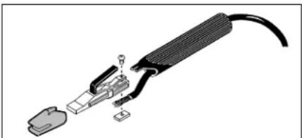
ELECTRODE HOLDER (ALL MODELS)
- Remove insulation handle from the holder body by pulling the two pieces apart.
- Slide the other weld cable through the handle.
- Loosen the wire clamping screw and slide the bare cord wire under the clamp block. Tighten the clamping screw making sure the wire is secure.
- Slide the handle over the electrode holder body and press to stop. Make sure the handle is secure and there is no exposed metal on the holder.
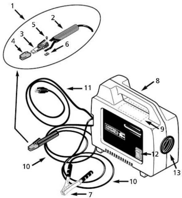
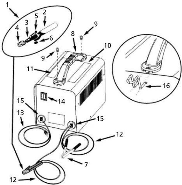
natural_image
Exploded view diagram of a cable and connector assembly (no text or symbols)Figure 6 - Electrode Holder Assembly
HANDSHIELD (ALL MODELS EXCEPT WS1020)
- Cut retainer stiffeners and detachable handle away from shield. Trim the excess plastic to remove sharp edges.
- Insert filter lens.
- Attach the stiffeners over the pins on the lens retainers (See Figure 7).
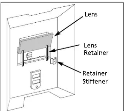
Figure 7
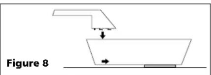
- To attach the handle, place shield on a flat surface and press handle into place (See Figure 8). *Not necessary for models WS0900 or WS090001.
NOTE: If you have never welded before or have little experience, a full face helmet is recommended. Both hands are needed to stabilize and control the angle and arc length of the electrode.
Welding Helmet Assembly
MODEL WT1000
- Remove the lens retainer from the face shield with a regular screwdriver by prying against the shield and post of the lens retainer.
- Remove the protective film covering from both sides of each lens cover. Put one clear lens cover on each side of the shaded lens. Place these three lenses together into the face shield and secure with the lens retainer. The lens retainer should snap into the second notch in the face shield.
- Position one of the holes in the adjustment arm over the pins which are located in the ear area of the face shield. These adjustment arms control the closeness of fit and can be easily repositioned if necessary.
- Position the headgear inside the face shield. Assemble the helmet by inserting the stud screw through the headgear and shield into the tension nut as shown. Do not tighten tension nut completely.
- Trial fit the welding helmet. Adjust headgear ratchet band to a comfortable position and lower the face shield. If the shield is too far or too close to the face, use a different hole in the adjustment arm. Adjust the tension nuts so that helmet can be easily lowered over the face by nodding the head.
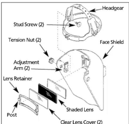
Figure 9
Operation
- Be sure to read, understand, and comply with all precautions in the General Safety Information section. Be sure the entire section entitled Guidelines prior to using the equipment.

-
Turn welder off and plug into appropriate receptacle:
115v-15 amp - 1/16 electrodes
115v-20 amp - 5/64 electrodes -
Verify that the surfaces of metals to be joined are free from dirt, rust, paint, oil, scale or other contaminants. These contaminants make welding difficult and cause poor welds.
WARNING
All persons operating this
equipment or in the area while equipment is in use must wear protective welding gear including: eye protection with proper shade as specified in the following chart, flame resistant clothing, leather welding gloves, and full foot protection.
WARNING
If heating, welding, or cutting materials that are galvanized, zinc plated, lead, or

cadmium plated refer to the General Safety Information Section for instructions. Extremely toxic fumes are created when these metals are heated.
- Connect the work clamp to the work piece. Make sure the contact is on bare metal and not obstructed by paint, varnish, corrosion, or non-metallic materials.
- Insert the exposed part of the electrode rod (the end with no flux) into the jaws of the electrode holder.
- Set the amperage adjustment knob, or the Low/High switch to the proper amperage for the electrode rod diameter. Refer to the following chart for proper electrode current settings.
▲WARNING
The electrode holder and rod are
electrically "live" (current potential) when the welder is on.
Electrode Current Diameter Setting (Amps)
1/16" (1.6 mm) 35-80 Low-WS090001
5/64" (2 mm) 45-100 High-WS090001
For specific settings, see weld guide marked on welder (not available on WS090001)
Operation (Con't)
WARNING
Grounding against any metallic surface
may produce an arc which could cause sparks and damage eyesight.
- Hold the electrode rod away from the grounded work piece or workbench. Turn on the welder.
- Position the electrode to begin weld, lower the welding helmet or position the hand shield, and strike an arc. Adjust weld amperage as needed.
- When finished welding, turn welder off and store properly.
DUTY CYCLE / THERMOSTATIC PROTECTION
Welder duty cycle is the percentage of actual weld time that can occur in a ten minute interval. For example, at a 10% duty cycle, actual welding can occur for one minute, then the welder must cool for nine minutes.
Internal components of this welder are protected from overheating with an automatic thermal switch. A yellow lamp is illuminated on the front panel (on/off switch) if the duty cycle is exceeded. On Model WS090001, the yellow lamp is located next to on/off switch. Welding operations may continue when the yellow lamp is no longer illuminated.
Maintenance
▲WARNING
Disconnect power supply and turn
machine off before inspecting or servicing any components.
Before every use;
- Check condition of weld cables and immediately repair or replace any cables with damaged insulation.
-
Check condition of power cord and immediately repair or replace any cord if damaged.
-
Check condition of electrode holder insulating pieces and immediately replace cracked or missing insulators. Verify that all fasteners are tight and insulated.
▲WARNING
Do not operate this welding machine
with cracked or missing insulation on welding cables, electrode holder, or power cord.
Every 3 months;
Replace any unreadable labels on the welder. Use compressed air to blow all dust and lint from the ventilation openings.
Welding Guidelines
General
This line of welding machines utilizes a process known as Shielded Metal-Arc Welding (SMAW). This process is used to bond metals by heating them with an electric arc created between the electrode and the work piece.
Electrodes used for shielded metal arc welding have two parts. The inner core is a metal rod or wire that should be similar in composition to the base metal. The outer coating is called flux. Various types of flux exist. Each coating is used for a particular welding situation.
While the metal is molten, it can be contaminated by elements in the air. This contamination could weaken the weld. The flux coating creates a protective barrier called slag that protects the molten metal from contaminants.
When current (amperage) flows through the circuit to the electrode, an arc is formed between the end of the electrode and the work piece. The arc melts the electrode and the work piece. The melted metal of the electrode flows into the molten crater and forms a bond with the work piece as shown in Figure 10.
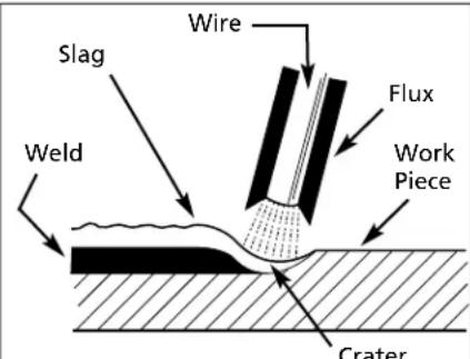
Figure 10 - Weld Components
NOTE: Discontinue using and discard electrodes that burn down to 1 to 2 inches from the electrode holder.
STRIKING AN ARC
Place the bare end of the electrode in the holder. Grip the holder lightly to reduce tiring of the hand and arm.
NOTE: Always keep the jaws of the holder clean to insure good electrical contact with the electrode.
⚠ WARNING
Be careful not to touch the work
piece or welding bench with the electrode as this causes arc flashes.
The best method of striking an arc is the scratching method. Drag the electrode at an angle along the surface much like striking a match. Upon contact with the plate, lift the electrode approximately
1/16" off the surface or it will stick (See Figure 11).
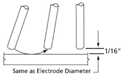
Figure 11 - Scratching Method
NOTE: Should the electrode stick to the work piece, break it loose by quickly twisting or bending at the holder while pulling upward. If the electrode does not break loose, disengage the electrode by releasing it from the holder.
ELECTRODE TYPE AND SIZE
Two types of electrodes are recommended for this welder. The electrodes are commonly known by the AWS (American Welding Society) designation as follows:
1. E-6013 GENERAL PURPOSE
- All position, smooth deposit rod with low spatter.
- For all mild steel and general purpose work.
Welding Guidelines (Continued)
2. E-7014 FAST FILL
- Smooth bead and fast deposition
- Ideal for joints with poor fitup and general repair work
NOTE: E-6011 and E-6018 are not recommended for use with these welders. Recommended electrode diameter is 1/16" or 5/64". Call (800) 746-5641 for availability.
Arc Welding Basics
Four basic techniques affect weld quality. These are: amperage setting, weld angle, arc length, and travel speed. Proper use of these techniques is necessary for good weld quality.
AMPERAGE SETTING
The correct amperage involves the adjustment of the welding machine to the required amp setting. This is regulated by a knob on the welder, or by selecting the appropriate high or low setting. The amperage required depends on the size (diameter) of electrode used and the thickness of the work piece.
Consult specifications listed on the welder. Excessive amps burn through light metals and the weld bead is flat and porous (See Figure 13). The bead appears high and irregular if the amperage is too low.
WELD ANGLE
Weld angle is the angle at which the electrode is held during the welding process. Using the correct angle ensures proper penetration and bead formation. Electrode angle involves two positions - travel angle and work angle (See Figure 12).
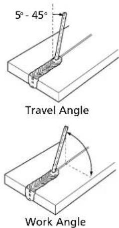
Figure 12 - Weld Angle
Travel angle is the angle in the line of welding and may vary from 5° to 45° from the vertical, depending on welding conditions. Work angle is the angle from horizontal, measured at right angles to the line of welding.
For most applications, a 45° travel angle and 45° work angle is sufficient. For specific applications, consult an arc welding handbook.
NOTE: Right handed welders should weld from left to right. Left handed welders should weld from right to left. The electrode should always point into the weld puddle as shown.
ARC LENGTH
Arc length is the distance from the work piece to the tip of the electrode, the distance which the arc must travel. A proper arc length is essential to generate the heat needed for welding (See Figure 13). An arc that is too long produces an unstable arc, reduces penetration, increases spatter, and causes flat and wide beads. Too short an arc does not create enough heat to melt the work piece, the electrode has a tendency to stick, penetration will be poor, and uneven beads with irregular ripples result. A proper arc should be no longer then the diameter of the rod. The sound of a proper arc is a steady, crisp sizzle, similar to bacon frying.
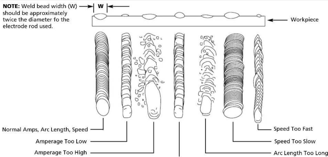
Figure 13 - Weld Appearance
Arc Length Too Short
Welding Guidelines (Continued)
TRAVEL SPEED
The travel speed is the rate at which the electrode is moved across the weld area (See Figure 13). When the speed is too fast, the bead is narrow and bead ripples are pointed as shown. When the speed is too slow, the weld metal piles up and the bead is high and wide. To control travel speed, watch the width of the weld bead (not the arc) when welding. The weld bead is the orange, molten metal behind the arc. The width should be approximately twice the diameter of the welding rod. Control travel speed to obtain a consistent bead width.
SLAG REMOVAL
▲WARNING
Wear ANSI approved safety
glasses (ANSI Standard Z87.1) and protective clothing when removing slag. Hot, flying debris can cause personal injury to anyone in the area.
After completing the weld, wait for the welded sections to cool. A protective coating called slag now covers the weld bead which prevents contaminants in the air from reacting with the molten metal. Once the weld cools to the point that it is no longer glowing red, the slag can be removed. Removal is done with a chipping hammer. Lightly tap the slag with the hammer and break it loose from the weld bead. The final clean-up is done with a wire brush. When making multiple weld passes, remove the slag before each pass.
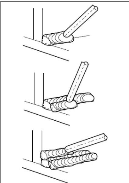
WELDING POSITIONS
Four basic welding positions can be used; flat, horizontal, vertical, and overhead. Welding in the flat position is easier than any of the others because welding speed can be increased, the molten metal has less tendency to run, better penetration can be achieved, and the work is less fatiguing.
Other positions require different techniques such as a weaving pass, circular pass, and jogging. A higher skill level is required to complete these welds. All work should be performed in the flat position if possible. For specific applications, consult an arc welding handbook.
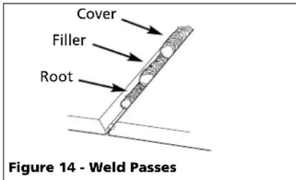
WELD PASSES
Sometimes more then one pass is necessary to fill the joint. The root pass is first, followed by filler passes and the cover pass (See Figure 14). If the pieces are thick, it may be necessary to bevel the edges that are joined at a 60° angle. Remember to remove the slag before each pass.
natural_image
Three-step diagram showing a tool interacting with a wooden post, no text or symbols presentFigure 15 - Multiple Weld Passes
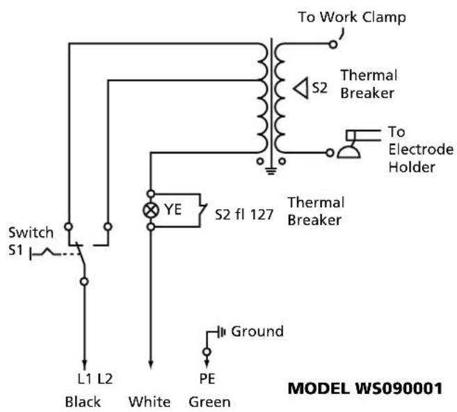
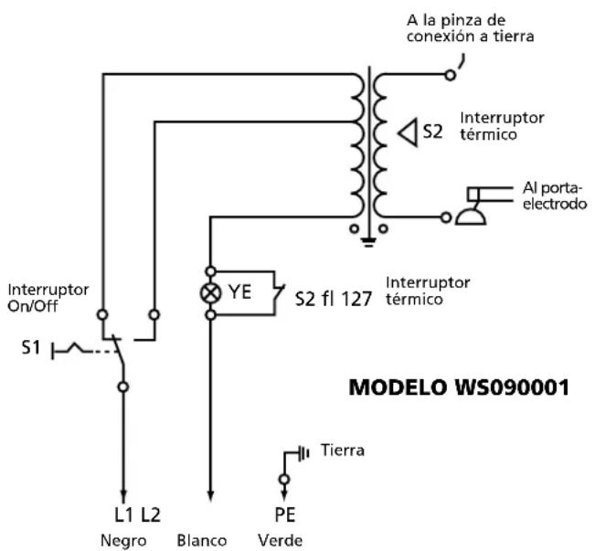
Supply Cable Replacement (See Wiring Schematics, Figure 16)
- Verify that welder is OFF and power cord disconnected.
-
Remove welder cover to expose the ON/OFF switch.
-
Disconnect the black and white power cord wires connected to the ON/OFF switch.
- Disconnect the green power cord wire connected to welder frame. (Not on WS0900)
- Loosen the cord strain relief screw(s) and pull cord out of strain relief.
- Install new cord in reverse order.
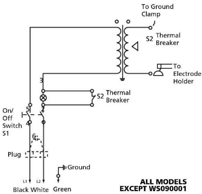
Figure 16 - Wiring Schematics
For Information About This Product, Call 1-800-746-5641
| Troubleshooting Chart - Welder | ||
| Symptom Possible Cause(s) Corrective Action | ||
| Welder does not hum when turned on | 1. No power at receptacle2. Broken or damaged power cable | 1. Check circuit fuse or circuit breaker2. Power cable requires service |
| Welder hums but does not weld | 1. Inadequate current at electrode2. Poor connections at welder | 1. Check work clamp, cable and connection to work piece.Check electrode cable and clamp2. Check all welder external connections |
| Welder gives trickle shocks | 1. Accidental contact with work piece2. Current leakage caused by moist clothing or work area | 1. Avoid contact with work piece2. Make sure clothing and work area are dry |
| Welder overheats - blows fuses, trips circuit breaker | 1. Use of extension cord2. Electrode diameter too large3. Overloaded circuit | 1. If possible, relocate welder to avoid use of extension cord. If relocation of welder is not possible, use thicker (lower gauge number) extension cord2. Use smaller diameter electrode3. Welder requires a dedicated 115V circuit |
| Arc difficult to strike | 1. Wrong type of electrode2. Electrode diameter too large3. Work piece not properly grounded4. Heavy loads making power line voltage low | 1. Verify that electrode is for alternating current (AC) use2. Use smaller diameter electrode3. Verify proper grounding. (No paint, varnish or corrosion)4. Run welder on dedicated 115V circuit |
Troubleshooting Chart - Welds
Symptom Possible Cause(s) Corrective Action
| Bead is intermittently too thin or too thick | 1. Inconsistent travel speed2. Output amp setting incorrect | 1. Carefully watch and control the width of the molten weld bead2. Adjust output amp setting or change to smaller diameter electrode |
| Ragged depressions at edge of weld | 1. Travel speed too fast2. Arc length too short3. Output amp setting too high | 1. Watch orange molten weld puddle and control bead width2. Practice running electrode across workpiece with welder OFF3. Reduce output amp setting |
| Weld bead does not penetrate workpiece | 1. Inconsistent travel speed2. Output amp setting too low3. Electrode diameter too large | 1. Decrease and maintain constant travel speed2. Increase output amp setting or change to smaller diameter electrode3. Recommend either 1/16 or 5/64 diameter |
| Electrode sticks to work piece | 1. Arc length short2. Amp setting low | 1. Lift electrode to correct arc length as soon as arc is struck2. Increase amp setting or change to smaller diameter electrode |
| Electrodes sputter and stick | Damp electrodes | Use dry electrodes and store in dry location |
Limited 5-3-1 Warranty
- Duration: The manufacturer warrants that it will repair, at no charge for parts or labor, the Welder, Welding Gun, or Cables, proven defective in material or workmanship, during the following time period(s) after date of original retail purchase:
For 5 Years: The Welder Transformer and Rectifier
For 3 Years: The Entire Welder (excluding clamps, welding gun, electrode holder, cables, or accessories packed with welder)
For 1 Year: The Welding Clamps, MIG Gun, Electrode Holder, Accessories, and Welding Cables (as applicable)
- Who Gives This Warranty (Warrantor):
The Campbell Group / A Scott Fetzer Company
100 Production Drive
Harrison, OH 45030
Telephone: (513)-367-4811
-
Who Receives This Warranty (Purchaser): The original purchaser of the Campbell Hausfeld product.
-
What is covered under this warranty: Defects in material and workmanship which occur within the duration of the warranty period. This warranty extends to the Welder, the Welders Transformer and Rectifier, Welding Gun or Electrode Holder, and cables only.
-
What is not covered under this warranty:
A. Implied warranties, including those of merchantability and FITNESS FOR A PARTICULAR PURPOSE ARE LIMITED IN DURATION TO THIS EXPRESS WARRANTY. After this period, all risks of loss, from whatever reason, shall be on the purchaser. Some states do not allow limitations on how long an implied warranty lasts, so above limitations may not apply to you.
B. ANY INCIDENTAL, INDIRECT, OR CONSEQUENTIAL LOSS, DAMAGE, OR EXPENSE THAT MAY RESULT FROM ANY DEFECT FAILURE OR MALFUNCTION OF THE CAMPBELL HAUSFELD PRODUCT. Some states do not allow limitations on how long an implied warranty lasts, so above limitations may not apply to you.
C. This warranty does not apply to any accessory items included with the product which are subject to wear from usage; the repair or replacement of these items shall be at the expense of the owner. These MIG items include but are not limited to; Contact Tips, Nozzles, Gun Liners, Drive Rollers, Felt Wire Cleaner. In addition, this warranty does not extend to any damage caused by the untimely replacement or maintenance of any of the previously listed CONSUMABLE parts.
D. Any failure that results from accident, purchaser's abuse, neglect or failure to operate products in accordance with instructions provided in the owner's manual(s) supplied with the product.
E. Pre-delivery service, i.e. assembly and adjustment.
-
Responsibilities of Warrantor under this warranty: Repair or replace, at Warrantor's option, products or components which have failed within duration of the warranty period.
-
Responsibilities of purchaser under this warranty:
A. Deliver or ship the Campbell Hausfeld product or component to Campbell Hausfeld. Freight costs, if any, must be borne by the purchaser.
B. Use reasonable care in the operation and maintenance of the products as described in the owner's manual(s).
- When Warrantor will perform repair or replacement under this warranty: Repair or replacement will be scheduled and serviced according to the normal work flow at the servicing location, and depending on the availability of replacement parts.
This Limited Warranty gives you specific legal rights and you may also have other rights which vary from state to state.
For Replacement Parts, call 1-800-746-5641
Please provide following information:
- Model number
- Serial number (if any)
- Part description and number as shown in parts list
Address parts correspondence to:
The Campbell Group
Attn: Parts Department
100 Production Drive
Harrison, Ohio 45030
WS0900

WS090001
Replacement Parts List - Model WS0900
| RefNo. | Description | WS0900 | Qty |
| 1 Electrode holder assembly - Cord not included (Includes reference numbers 2-6) WC200000AV 1 | |||
| 2 Electrode holder handle (Cord not included) WC200001AV 1 | |||
| 3 Electrode holder body WC200002AV 1 | |||
| 4 Insulation cap WC200003AV 1 | |||
| 5 #10-24 x .5" Machine screw * 1 | |||
| 6 #10-24 x 7/16" Square nut * 1 | |||
| 7 Work clamp (Cord not included) WC100000AV 1 | |||
| 8 Safety decal (Right) DK670000AV 1 | |||
| 9 Safety decal (Left) DK670001AV 1 | |||
| 10 Welding cable 6 AWG (6 ft) * 2 | |||
| 11 Power cord 14-2 AWG (6 ft)Type SJT WC000400AV 1 | |||
| 12 On/Off switch WC400100AV 1 | |||
| 13 Hand wheel | WC302100AV 1 | ||
| * Standard hardware item, available at local hardware or welder supply store | |||
Replacement Parts List - Model WS090001
| RefNo. | Description | WS090001 | Qty |
| 1 Electrode holder assembly - Cord not included (Includes reference numbers 2-6) WC200000AV 1 | |||
| 2 Electrode holder handle (Cord not included) WC200001AV 1 | |||
| 3 Electrode holder body WC200002AV 1 | |||
| 4 Insulation cap WC200003AV 1 | |||
| 5 #10-24 x .5" Machine screw * 1 | |||
| 6 #10-24 x 7/16" Square nut * 1 | |||
| 7 Work clamp | WC100300AV 1 | ||
| 8 Handle | WC301300AV 1 | ||
| 9 #8-36 x 3/4" pan head screw | * 2 | ||
| 10 Safety decal (right) | DK670000AV 1 | ||
| 11 Safety decal (left) | DK670001AV 1 | ||
| 12 Welding cable 6 AWG (6 ft) * 2 | |||
| 13 Power cord 14-3 AWG (6 ft) Type SJT WC000100AV 1 | |||
| 14 High/off/low thermal indicator | WC401000AV 1 | ||
| 15 Strain relief | WC102000AV 2 | ||
| 16 Cord storage clip | WC301301AV 2 | ||
| * Standard hardware item, available at local hardware or welder supply store | |||
For Replacement Parts, call 1-800-746-5641
Please provide following information:
- Model number
- Serial number (if any)
- Part description and number as shown in parts list
Address parts correspondence to:
The Campbell Group
Attn: Parts Department
100 Production Drive
Harrison, Ohio 45030

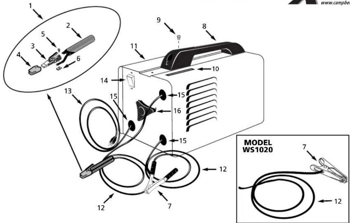
Replacement Parts List - Models WS0950, WS1000 and WS1020
| RefNo. | Description | Part Number Qty |
| 1 | Electrode holder assembly - Cord not included (Includes reference numbers 2-6) WC200000AV 1 | |
| 2 | Electrode holder handle (Cord not included) WC200001AV 1 | |
| 3 | Electrode holder body WC200002AV 1 | |
| 4 | Insulation cap WC200003AV 1 | |
| 5 | #10-24 x .5" Machine screw * 1 | |
| 6 | #10-24 x 7/16" Square nut * 1 | |
| 7 | Work clamp (Cord not included) WC100000AV 1 | |
| Model WS1020 only WC100100AV 1 | ||
| 8 | Handle WC300000AV 1 | |
| 9 | #8-36 x 1.5" Pan head screw * 1 | |
| 10 | Amperage window WC800000AV 1 | |
| Model WS1020 only WC800100AV 1 | ||
| 11 | Safety decal DK670100AV 1 | |
| 12 | Welding cable 6 AWG (6 ft) | * 2 |
| 13 | Power cord 14-3 AWG (6 ft) Type SJT | WC000100AV 1 |
| 14 | On/Off switch | WC400000AV 1 |
| 15 | Strain relief | WC102000AV 3 |
| 16 | Hand wheel WC302000AV 1 |
* Standard hardware item, available at local hardware or welder supply store
Glossary of Welding Terms
AC or Alternating Current - electric current that reverses direction periodically. Sixty cycle current travels in both directions sixty times per second.
Arc Length - the distance from the end of the electrode to the point where the arc makes contact with the work surface.
Base Metal - the material to be welded.
Butt Joint - a joint between two members aligned approximately in the same plane.
Crater - a pool, or pocket, that is formed as the arc comes in contact with the base metal.
DC or Direct Current - electric current which flows only in one direction. The polarity (+ or -) determines which direction the current is flowing.
DC Reverse Polarity - occurs when the electrode holder is connected to the positive pole of the welding machine. Reverse Polarity directs more heat into melting the electrode rather than the work piece. It is used on thinner material.
DC Straight Polarity - occurs when the electrode holder is connected to the negative pole of the welding machine. With straight polarity more heat is directed to the work piece for better penetration on thicker material.
Electrode - a coated metal wire having approximately the same composition as the material being welded.
Fillet Weld - approximately a triangle in cross-section, joining two surfaces at right angles to each other in a lap, T or corner joint.
Flux - the coating on arc-welding rods and in flux-cored welding wire that is consumed in the arc to produce a shielding gas. This gas displaces air and impurities from around the weld.
Flux Cored Arc Welding (FCAW) - also called Gasless, is a welding process used with a wire-feed welding machine. The weld wire is tubular with flux material contained inside for shielding.
Gas Metal Arc Welding (GMAW) - also called MIG, is a welding process used with a wire feed welding machine. The wire is solid and an inert gas is used for shielding.
Gas Tungsten Arc Welding (GTAW) - also called TIG, is a welding process used with welding equipment with a high frequency generator. The arc is created between a non-consumable tungsten electrode and the work piece. Filler metal may or may not be used.
Lap Joint - a joint between two overlapping members in parallel planes.
Open Circuit Voltage (OCV) - the voltage between the electrode and the work clamp of the welding machine when no current is flowing (not welding). The OCV determines how quickly the arc is struck.
Overlap - occurs when the amperage is set too low. In this instance, the molten metal falls from the electrode without actually fusing into the base metal.
Porosity - gas pockets, or cavities, formed during weld solidification. They weaken the weld.
Penetration - the depth into the work piece that has been heat effected by the arc during the welding process. A good weld achieves 100% penetration meaning that the entire thickness of the work piece has been heated and resolidified. The heat effected area should be easily seen on the opposite side of the weld.
Shielded Metal Arc Welding (SMAW) - also called Stick, is a welding process with uses a consumable electrode to support the arc. Shielding is achieved by the melting of the flux coating on the electrode.
Slag - a layer of flux soot that protects the weld from oxides and other contaminants while the weld is solidifying (cooling). Slag should be removed after weld has cooled.
Spatter - metal particles thrown from the weld which cool and harden on the work surface. Spatter can be minimized by using a spatter resistant spray on the work piece before welding.
Tack Weld - weld made to hold parts in proper alignment until final welds are made.
Travel Angle - the angle of the electrode in the line of welding. It varies from 5° to 45° depending on welding conditions.
T Joint - made by placing the edge of one piece of metal on the surface of the other piece at approximately a 90^ angle.
Undercut - a condition that results when welding amperage is too high. The excessive amperage leaves a groove in the base metal along both sides of the bead which reduces the strength of the weld.
Weld Pool or Puddle - a volume of molten metal in a weld prior to its solidification as weld metal.
Weld Bead - a narrow layer or layers of metal deposited on the base metal as the electrode melts. Weld bead width is typically twice the diameter of the electrode.
Work Angle - the angle of the electrode from horizontal, measured at right angles to the line of welding.
Norme ANSI Z49.1 de l' American Welding Society, 550 N.W. LeJune Rd. Miami, FL 33126
OSHA 29 CFR 1910, du Superintendent of Documents, U.S. Government Printing Office, Washington, D.C. 20402
National Electrical Code (Code Électrique National)
Norme NFPA 70, du National Fire Protection Association, Batterymarch Park, Quincy, MA 02269
Safe Handling of Compressed Gases in Cylinders (Manipulation Sûr des Gaz Comprimés en Cylindres)
CGA Pamphlet P-1, du Compressed Gas Association, 1235 Jefferson Davis Highway, Suite 501, Arlington, VA 22202
Norme CSA W117.2, du Canadian Standards Association, Standards Sales, 178 Rexdale Boulevard, Rexdale, Ontario, Canada M9W 1R3
natural_image
Technical line drawing of a portable electronic device with a handle and control panel (no text or symbols)natural_image
Exploded view diagram of a cable and connector assembly (no text or symbols)natural_image
Simple line drawing of a mechanical component with an arrow indicating motion (no text or symbols)Figure 8
Directives De Soudage (Suite)
Directives De Soudage (Suite)
LONGUEUR DE L'ARC
natural_image
Simple line drawing of a tool interacting with a surface (no text or symbols)
natural_image
Simple line drawing of a hammer striking a surface with a wooden stick (no text or symbols)
natural_image
Diagram of a mechanical joint or clamping operation with coiled rods and a dashed line indicating a reference (no text or symbols present)Figure 15 - Passes Multiples De Soudage
The Campbell Group/ A Scott Fetzer Company
100 Production Drive
Harrison, OH 45030
Telephone: (513)-367-4811
The Campbell Group
Attn: Parts Department
100 Production Drive
Harrison, Ohio 45030 U.S.A.

WS0900
WS090001
The Campbell Group
Attn: Parts Department
100 Production Drive
Harrison, Ohio 45030 U.S.A.
2,0 mm (5/64") 20 amp

natural_image
Technical line drawing of a portable electronic device with mounting bracket and control panel (no text or symbols)natural_image
Diagram of a portable kitchen appliance with a handle and control panel (no text or symbols)natural_image
Technical line drawing of a mechanical lever assembly with motion arrows (no text or symbols)natural_image
Simple line drawing of a hammer striking a surface with no text or symbols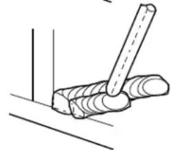
natural_image
Simple line drawing of a tool interacting with a coiled object (no text or symbols)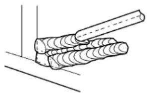
natural_image
Diagram of a mechanical joint or clamping device with coiled cylindrical components (no text or symbols)Figura 15 - Pasos múltiples
A Scott Fetzer Company
100 Production Drive
Harrison, OH 45030
Attn: Parts Department
100 Production Drive
Harrison, Ohio 45030 U.S.A.
WS0900
WS090001
Attn: Parts Department
100 Production Drive
Harrison, Ohio 45030 U.S.A.
Lista de Repuestos - Modelos WS0950, WS1000 and WS1020


- CAMPBELL HAUSFELD™
- Shielded Metal
- Arc Welder
- Description
- Unpacking
- Circuit Requirements
- ▲ CAUTION
- Components and Controls
- General Safety
- DANGER
- ▲WARNING
- General Safety (Con't)
- WARNING
- ⚠ WARNING
- ADDITIONAL SAFETY STANDARDS
- Safety and Health Standards
- National Electrical Code
- Safe Handling of Compressed Gases in Cylinders
- Code for Safety in Welding and Cutting
- Cutting And Welding Processes
- Safe Practices For Occupational And Educational Eye And Face Protection
- Installation
- Location
- Assembly
- HANDLE ASSEMBLY-MODELS WS0950, WS1000 AND WS1020 ONLY
- HANDLE ASSEMBLY- MODEL WS090001 ONLY
- WORK CLAMP (WS0900, 950, 1000 AND 1020)
- Assembly (Con't)
- ELECTRODE HOLDER (ALL MODELS)
- HANDSHIELD (ALL MODELS EXCEPT WS1020)
- Welding Helmet Assembly
- MODEL WT1000
- Operation
- Electrode Current Diameter Setting (Amps)
- Operation (Con't)
- DUTY CYCLE / THERMOSTATIC PROTECTION
- Maintenance
- Welding Guidelines
- General
- STRIKING AN ARC
- ELECTRODE TYPE AND SIZE
- E-6013 GENERAL PURPOSE
- Welding Guidelines (Continued)
- E-7014 FAST FILL
- Arc Welding Basics
- AMPERAGE SETTING
- WELD ANGLE
- ARC LENGTH
- TRAVEL SPEED
- SLAG REMOVAL
- WELDING POSITIONS
- WELD PASSES
- Supply Cable Replacement (See Wiring Schematics, Figure 16)
- Limited 5-3-1 Warranty
- For Replacement Parts, call 1-800-746-5641
- Replacement Parts List - Models WS0950, WS1000 and WS1020
- Glossary of Welding Terms
- National Electrical Code (Code Électrique National)
- Safe Handling of Compressed Gases in Cylinders (Manipulation Sûr des Gaz Comprimés en Cylindres)
- Directives De Soudage (Suite)
- LONGUEUR DE L'ARC
Brand : Campbell Hausfeld
Model : WS099001AV
Category : Welding machine