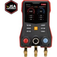
UT336E - Measuring equipment Uni-T - Free user manual and instructions
Find the device manual for free UT336E Uni-T in PDF.


| Product type | Digital refrigerant pressure gauge |
| Brand | Uni-T |
| Model | UT336E |
| Power supply | Rechargeable lithium battery 3.7 V 5200 mAh |
| Battery life | > 30 h (backlight at 50%, wireless connection disabled) |
| Charging time | Approximately 4.5 hours |
| Display | 3.5-inch TFT color screen |
| Pressure range | -1.00 ~ +60.00 bar (0.01 bar resolution) |
| Temperature range (with UT320i) | -50 ~ 150 °C |
| Pressure accuracy | ±0.5% FS |
| Temperature accuracy (UT320i) | ±0.5 °C (-50 ~ 80 °C), ±1 °C elsewhere |
| Ingress protection (UT336E) | IP54 |
| Ingress protection (UT320i) | IP65 |
| Key functions | Dual-channel pressure and temperature measurement, Refrigeration, Evacuation, Pressure test, Delta T modes, database of 162 refrigerants, automatic superheat/subcooling calculation, data recording up to 10,000 records, mobile app |
| Wireless connection | Bluetooth, up to 100 m in open space, compatible with UT320i (up to 2) and UT336V |
| Auto power off | Screen: 1/5/10 min adjustable; device: 15/30 min adjustable or disable |
| Maintenance and cleaning | Clean gently with a soft cloth and a little clean water. Avoid alcohol, solvents, and abrasive products. |
| Safety | Do not use with refrigerants containing ammonia. Check the device before use. Charge only with 5 V DC adapter. |
| Spare parts and repairability | Contact Uni-T customer service for spare parts and warranty repairs. |
| General information | Digital pressure gauge for refrigeration systems, supplied with user manual, USB-C cable, and (depending on KIT version) 2 UT320i clamps and 3 charging hoses. |
Frequently Asked Questions - UT336E Uni-T
User questions about UT336E Uni-T
0 question about this device. Answer the ones you know or ask your own.
Ask a new question about this device
Download the instructions for your Measuring equipment in PDF format for free! Find your manual UT336E - Uni-T and take your electronic device back in hand. On this page are published all the documents necessary for the use of your device. UT336E by Uni-T.
USER MANUAL UT336E Uni-T
No.6, Gong Ye Bei 1st Road
Songshan Lake National High-Tech Industrial
Development Zone, Dongguan City,
Guangdong Province, China
UNI-T

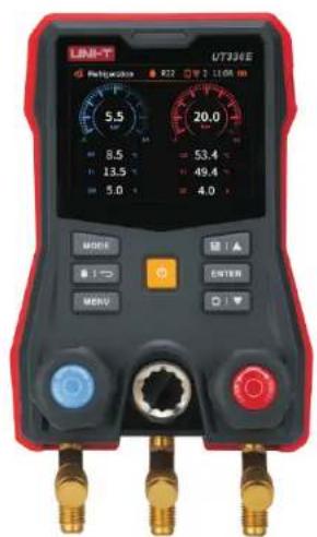
UT336E/UT336E KIT
Digital Manifold Gauge with
Wireless Temperature Clamps User Manual
EN
PREFACE
Thank you for purchasing the new Digital Manifold Gauge. In order to use this product safely and correctly, please read this User Manual thoroughly, especially the Safety part. After reading this guideline, it is recommended to keep the manual and product at an easily accessible place, preferably close to the device, for future reference.
LIMITED WARRANTY AND LIABILITY
Uni-Trend guarantees that the product is free from any defect in material and workmanship within one year since the purchase date. This warranty does not apply to damages caused by accident, negligence, misuse, modification, contamination and improper handling. The dealer shall not be entitled to give any other warranty on behalf of Uni-Trend. If you need warranty service within the warranty period, please contact your seller directly.
This warranty is the only compensation you can obtain. Besides, Uni-Trend does not provide any express or implied warranty, e.g. an implied warranty for some particular purpose. Uni-Trend will not be responsible for any special, indirect, incidental or subsequent damage or loss caused by any reason or speculation. As some areas or countries do not allow limitations on implied warranties and incidental or subsequent damage, the above limitation of liability and stipulation may not apply to you.
Content
- Introduction 4
- Features 4
- Configuration 4
4.Safety 5 - Buttons 5
6.Operations 6 - Modes 9
- Specification 13
- Mobile APP Download 46
10.Maintenance 46
1. Introduction
The UT336E Digital Manifold Gauge (also called AC Diagnoser) integrates functions of pressure and temperature measurement, mainly used for leak detections of refrigeration system (Pressure Holding Method), refrigerant charging, and the troubleshooting and maintenance of refrigeration system.
2. Features
- Equipped with a 3.5-inch TFT color screen, analog dial design, and attractive UI for measurement display and status.
- Dual-channel pressure measurement, Dual-channel temperature measurement (used with UT320i wireless temperature clamp).
Support 4 test mode:Refrigeration,Evacuation,Pressure Test,Delta T. - UT336E supports IP54 protection, while UT320i supports IP65 protection.
- Support mobile APPs for data viewing and report exporting.
- Built-in a database of 160+ refrigerants and with mobile APP updates. Automatically calculate the superheat (SH) and subcooling (SC) according to the Evaporation Temperature (EV) and Condensation Temperature (CO) from database at current pressures (used with UT320i wireless temperature clamp).
- Rechargeable lithium battery
- Auto screen off, with tap-to-wake backlight function.
Maximum 10,000 data storage.
3. Configuration
UT336E Digital Manifold Gauge
UT 320i Wireless Temperature Clamp-1 (For UT336E KIT only)
UT336E/UT336E KIT User Manual
UT320i User Manual-1 (For UT336E KIT only)
Safety Guide 1
Download Guide of Common Files 1
Refrigerant Hose 3 (For UT336E KIT only)
USB-C Charging Cable 1
Tool Box 1
Please contact your dealer directly if any components are missing or damaged.
4.Safety
Read the Safety carefully before you use the device.
- Please read instructions carefully and follow them before you start the measurement.
- UT336E is incompatible with refrigerants containing ammonia and must not be used together with ammonia refrigerants.
- Check the device and accessories before you use the device. Replace a new refrigerant hose when it gets broken by dropping or other damages. If the high/low-pressure valves are damaged, or the housing of device is damaged or no screen display occurs, do not continue to use the device.
- Do not disassemble or change the internal wires of device randomly.
- When the low battery icon shows on the screen, charge the battery to ensure its normal use and accurate measurement.
- Please charge the device using a standard DC 5V adapter. Do not use power supplies or adapters with other voltages, may cause damage.
- Do not store or use the device in high-temperature, high-humidity, flammable, explosive, or strong electromagnetic environments.
- Use soft cloth and neutral detergent to clean the housing of device. Do not use abrasives and solvents to avoid housing corrosion and device damage.
- Buttons
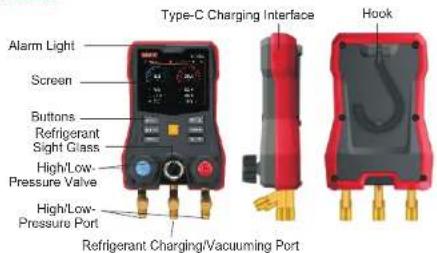
High/Low-Pressure Port: 1/4 SAE refrigerant hose connection; connect a blue hose to the left-side port (low-pressure port); connect a red hose to the right-side port (high-pressure port). Refrigerant Charging/Vacuuming Port: 1/4 SAE refrigerant hose connection, connect a yellow hose.
Button Details:
| Buttons | Short Press | Long Press | |
| MODE | Mode | Enter/Exit Mode Switching | x |
| Refrigerant/Return | Refrigerant/Menu Return | x | |
| Menu Setting | Enter/Exit the setting | x | |
| Power On/Off | x | Power on/off | |
| Record/UP | Start or stop recording/Scroll up | Scroll up fast | |
| Confirm | Confirm | x | |
| Zeroing/DOWN | Scroll down | Zeroing/Scroll down fast | |
6. Operations
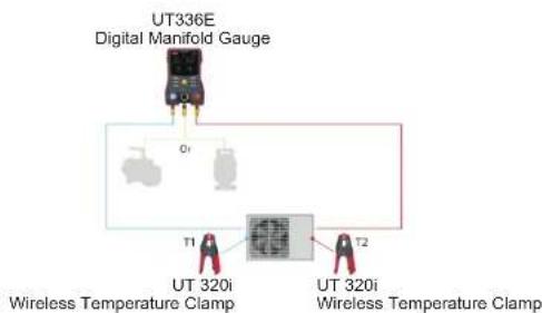
1) Quick Operations
UNI-T
UT336E/UT336E KIT UT336E/UT336E KIT
UNI-T
-
Long press POWER button to power on the device.
-
Refrigeration to select a refrigerant. Enter the mode and short press
- Press and hold the Zeroing button for 3 seconds for sensor zeroing.
- Connect the high-low pressure ports of the device to the measured system using refrigerant hoses.
- Rotate the high-low pressure valves clockwise to close.
- Clamp the wireless temperature clamp to the pipelines of the measured system.
- When adding refrigerant, connect a refrigerant tank to the middle port; when evacuating, connect a vacuum pump to the middle port.
- Start the measured system, and now you can monitor the real-time changes of pressure, temperature, saturation temperature, and other parameters at the high and low pressure of the system.
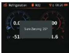
2) Zeroing
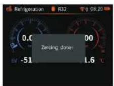
①. Long press Zeroing button
Zeoring or Not?
③. Zeoning Done (after 3s)
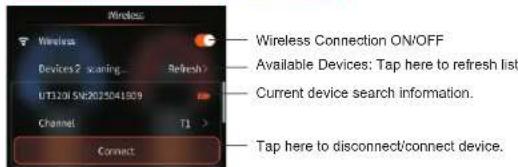
3) Wireless Temperature Clamp UT320i Pairing
7
①. Short press Menu button
②. Select wireless options
②. Follow the instructions above.
Select the device you want to connect in the wireless connection options, e.g. the UT320i Wireless Temperature Clamp and the UT336V Wireless Vacuum Gauge.
After the connection, recorded as a historical connection and automatically connect at next time.
After connecting UT320i Wireless Temperature Clamp, tap the 'Channel' to select T1 or T2.
The UT336E device only supports simultaneous connection of two UT320i Wireless Temperature Clamps and one UT336V Wireless Vacuum Gauge. To connect a new device, please manually disconnect the currently connected device first.
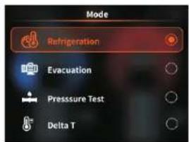
4) Mode Selection
①. Short press Mode button
Select one mode and confirm
8
7. Modes
1) Refrigeration Mode
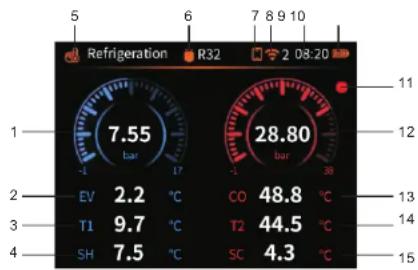
| 1 | Low Pressure Value |
| 2 | Evaporation Temperature |
| 3 | Measured Temperature T1 |
| 4 | Superheat |
| 5 | Refrigeration Mode |
| 6 | Refrigerant Type |
| 7 | Mobile Connection Icon |
| 8 | Wireless Connection Icon & Connected Slave Devices |
| 9 | Time |
| 10 | Battery Icon |
| 11 | Data Record Icon |
| 12 | High Pressure Value |
| 13 | Condensation Temperature |
| 14 | Measured Temperature T2 |
| 15 | Subcooling |
EV/CO:
Evaporation and condensation temperatures are automatically calculated based on the refrigerant's physical properties at different pressures.
T1/T2:
The measured surface temperatures of the low-pressure and high-pressure copper tubes
SH/SC: Superheat SH = T1 - EV Subcooling SC = CO-T2.
Operation Details:
①. Long press POWER button to power on the device.
②. Enter the Refrigeration mode and short press to select a refrigerant.
③. Press and hold the Zeroing button for 3 seconds for sensor zeroing.
③. Connect the high-low pressure ports of the device to the measured system using refrigerant hoses.
⑤. Rotate the high-low pressure valves clockwise to close.
⑧. Enter the wireless connection Setting interface to connect wireless temperature clamp T1 and T2 (If already connected, they will automatically connect after power-on).
⑦. Clamp the wireless temperature clamp to the pipelines of the measured system.
③ Start the measured system, and now you can monitor the real-time changes of pressure, temperature, saturation temperature, and other parameters.
2)Evacuation Mode
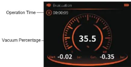
Operation Details:
- Long press POWER button to power on the device.
2 Enter the Refrigeration mode, zeroing the sensor.
3 Short press MODE button to select the Evacuation mode..
4 Connect the device's high-pressure (right side) port to the system requiring
evacuation.(The high-pressure channel is for evacuation test)
5 Connect the device's vacuum (middle) port to the vacuum pump..
6 Rotate the high-pressure valve counter-clockwise to open.
7 Tap 'Confirm' to begin vacuuming, and the device starts to record the operation.
time. The vacuum percentage will display once the system pressure is negative:
otherwise, it will show 0.
Note:
The evacuation function is using a non-professional vacuum sensor, and only for
monitoring the vacuum status of system roughly. For accurate vacuum measurement,
please use the UT336V Wireless Vacuum Gauge.
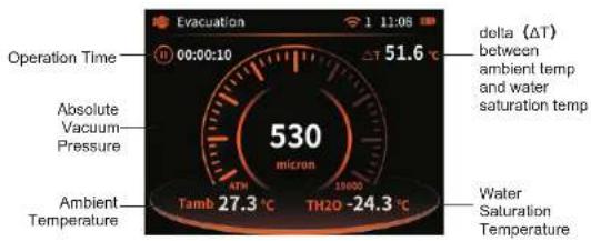
3) Connect UT336V Vacuum Gauge in Evacuation Mode
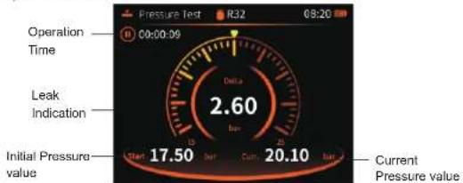
4) Pressure Test Mode
Operation Details:
Long press POWER button to power on the device.
2. Enter the Refrigeration mode, zeroing the sensor.
③. Short press MODE button to select the Pressure test mode.
Connect the device's high-pressure (right side) port to the measured system.
(The high-pressure channel is for pressure test.)
Rotate the high-pressure valves clockwise to close.
©. Tap 'Confirm' button to start the pressure test, and the device will record the
initial pressure, marking it with a triangle icon on the scale. Start to record the
operation time, and the scale will turn yellow if the system leaks.
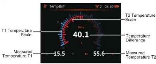
5) Delta T Mode
Operation Details:
Long press POWER button to power on the device.
② Short press MODE button to select the mode.Delta T
Enter the wireless connection options to connect wireless temperature clamp UT320i T1 and T2. (if already connected, they will automatically connect after power-on)
④ Clamp the wireless temperature clamp to the pipelines of the measured system, showing the measured T1, T2 and temperature difference value.
- Specification
| Pressure Range/ Resolution | -1.00~+60.00 bar | 0.01 bar |
| -100 +6000 kPa~ | 1 kPa | |
| -0.100~+6.000 MPa | 0.001 MPa | |
| -14.5~+870.2 psi | 0.1 psi | |
| -1.02~+61.18 kg/cm2 | 0.01 kg/cm2 | |
| -75.0 to 4500 cmHg | 0.1 cmHg | |
| -29.5 to 1771 inHg | 0.1 inHg | |
| Temperature Range/ Resolution (UT 320i) | -50 150°C~ | 0.1°C |
| -58 302°F~ | 0.1°F | |
| Pressure Accuracy | ±0.5% FS | |
| Temperature Accuracy (UT 320i) | \( \pm {0.5}^{ \circ }\mathrm{C}\left( {-{50}^{ \circ }{80}^{ \circ }\mathrm{C}}\right) , \pm {1}^{ \circ }\mathrm{C} \) for other | |
| Unit Memory | The device will remember your last unit selection when it starts up. | |
| Alarm | Yellow LED/Buzzer alarm, the alarm threshold can be set. | |
| Wireless Function | Can be connected with two UT320i, one UT336V and a mobile app simultaneously, range of up to 100 meters in open spaces. | |
| IP Rating | UT336E::IP54: UT320i: IP65 | |
| Measurement Modes | Refrigeration, Evacuation, Pressure Test. Delta T | |
| Refrigerant Type | 162,mobile APP can preset 10 common refrigerant types. | |
| Evaporation & Condensation Temperature | ✓ |
| High/Low-Pressure Measurement | ✓ |
| Superheat/Subcooling | ✓ |
| Pressure Zeroing | ✓ |
| Refrigeration/Heat Pump Mode | ✓ |
| Data Record | Maximum 10000, the record interval can be set. |
| Temperature Compensation | Support, suitable for pressure holding mode. With this function ON, it compensates for the temperature changes on the pressure sensor of device. |
| Auto Screen Off | 1/5/10minute can be set. It can be canceled, and it supports tapping to wake up the screen. |
| Auto Power Off | Auto power off after 15 or 30 minutes if no operations, can be set or canceled. |
| Battery | Built-in rechargeable lithium battery: 3.7V 5200mAh |
| Charging Voltage | 5V 2A |
| Charge Time & LED Indication | About 4.5 hours. LED in red indicates charging, while solid green indicates fully charged. |
| Battery Life | >30h, (backlight 50%, wireless connection OFF) |
| Working Temperature & Humidity | -20 - 50°C < 90%RH (non-condensing) |
| Storage Temperature & Humidity | -20 - 60°C < 90%RH (non-condensing) |
| Altitude | ≤2000m |
| EMC Standard | EN 61326-1:2021(Class A) |
| Size | UT336E: 203×117×70mm; UT320i 156×79×40mm: |
| Weight | UT336E: ~836g; UT320i: ~156g |
Built-in 160+ refrigerants
Prior to the release of this manual, 162 types of refrigerants had been cataloged in the databasa:
| R11 | R1123 | R113 | R114 | R115 | R1150 |
| R116 | R12 | R1216 | R123 | R1233ZDE | R1234YF |
| R1234ZEE | R1234ZEZ | R124 | R1243ZF | R125 | R1270 |
| R13 | R134A | R14 | R141B | R142B | R143A |
| R150 | R152A | R161 | R170 | R21 | R218 |
| R22 | R227EA | R23 | R236EA | R236FA | R245CA |
| R245FA | R290 | R32 | R40 | R401A | R401B |
| R401C | R402A | R402B | R403A | R403B | R404A |
| R405A | R406A | R407A | R407B | R407C | R407D |
| R407E | R407F | R407G | R407H | R408A | R409A |
| R409B | R41 | R410A | R410B | R411A | R411B |
| R412A | R413A | R414A | R414B | R415A | R415B |
| R416A | R417A | R417B | R417C | R418A | R419A |
| R419B | R420A | R421A | R421B | R422A | R422B |
| R422C | R422D | R422E | R423A | R424A | R425A |
| R426A | R427A | R428A | R429A | R430A | R431A |
| R432A | R433A | R433B | R433C | R434A | R435A |
| R436A | R436B | R437A | R438A | R439A | R440A |
| R441A | R442A | R443A | R444A | R444B | R445A |
| R446A | R447A | R447B | R448A | R449A | R449B |
| R449C | R450A | R451A | R451B | R452A | R452B |
| R452C | R453A | R454A | R454B | R454C | R455A |
| R456A | R457A | R458A | R459A | R459B | R460A |
| R460B | R466A | R469A | R50 | R500 | R501 |
| R502 | R503 | R504 | R507A | R508A | R508B |
| R509A | R510A | R511A | R512A | R513A | R513B |
| R515A | R600 | R600A | R601A | R718 | R744 |
9. Mobile APP Download
Download the mobile app iENV in the following ways:
a) For iOS, search and download iENV in the App Store.
b) For Android, search and download iENV in the Google Play.
10. Maintenance
1) Operating Environment: a precision instruments. To UT336E/UT320i are measurement accuracy, please keep it strictly away from impacts, severe ensure its moisture, strong electric fields, magnetic fields, oil, and dusty environments shocks.
2) Case Cleaning: Alcohol and thinners are corrosive to the case, especially the LCD screen. Please gently wipe it with a little clean water.
The User Manual is subject to change without prior notice!
Due to different batches, the materials and details of actual products may be slightly different from the graphic information, please refer to the actual product received. Experimental data provided in the page is from internal laboratory of UNI-T, but it should not be a reference for customer to place orders. Any questions, please contact the customer service, thanks!
UNI-T


UT336E/UT336E KIT
UT336E/UT336E KIT UT336E/UT336E KIT
UNI-T
4. Sécurité
UT336E/UT336E KIT UT336E/UT336E KIT
UNI-T
UT336E/UT336E KIT UT336E/UT336E KIT
UNI-T
UT336E/UT336E KIT UT336E/UT336E KIT
UNI-T
4. Sicherheit
UT336E/UT336E KIT UT336E/UT336E KIT
UNI-T
UT336E/UT336E KIT UT336E/UT336E KIT
UNI-T
4. Sicurezza
UT336E/UT336E KIT UT336E/UT336E KIT
UNI-T
UT336E/UT336E KIT UT336E/UT336E KIT
UNI-T
4. Sakerhet
UT336E/UT336E KIT UT336E/UT336E KIT
UNI-T
Driftdetailer
- PREFACE
- LIMITED WARRANTY AND LIABILITY
- Content
- Introduction
- Features
- Configuration
- 4.Safety
- Operations
- UNI-T
- UT336E/UT336E KIT UT336E/UT336E KIT
- Modes
- 1) Refrigeration Mode
- EV/CO:
- T1/T2:
- Operation Details:
- 2)Evacuation Mode
- Note:
- Built-in 160+ refrigerants
- Mobile APP Download
- Maintenance
- Sécurité
- Sicherheit
- Sicurezza
- Sakerhet
- Driftdetailer
Brand : Uni-T
Model : UT336E
Category : Measuring equipment