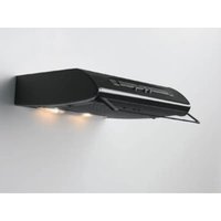
DVK5510SW - Range hood ELECTROLUX - Free user manual and instructions
Find the device manual for free DVK5510SW ELECTROLUX in PDF.


User questions about DVK5510SW ELECTROLUX
0 question about this device. Answer the ones you know or ask your own.
Ask a new question about this device
Download the instructions for your Range hood in PDF format for free! Find your manual DVK5510SW - ELECTROLUX and take your electronic device back in hand. On this page are published all the documents necessary for the use of your device. DVK5510SW by ELECTROLUX.
USER MANUAL DVK5510SW ELECTROLUX
natural_image
Line drawing of a mechanical device with a curved housing and internal components (no text or symbols)| DE | Bedienungsanleitung |
| FR | Manuel d’Instructions |
| IT | Libretto Istruzioni |
| GB | Instruction Manual |
DE
text_image
Diagram illustrating shopping order with a shopping cart icon and two circular insets showing a person moving through a cart, labeled 'W'.natural_image
Illustration of a hand holding a small object over a tablet screen, with 'ZZ' text visible (no other text or symbols)natural_image
Technical line drawing of a curved mechanical part with dimension annotations (no readable text or symbols)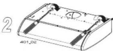
natural_image
Technical line drawing of a mechanical component with mounting holes and a curved housing (no text or symbols)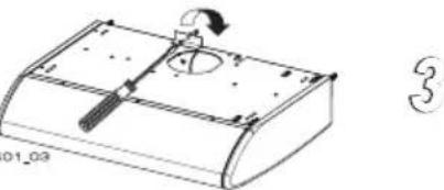
natural_image
Technical line drawing of a mechanical component with no visible text or symbolsnatural_image
3D technical diagram of a mechanical assembly with mounting base and cylindrical component (no text or symbols)natural_image
Diagram showing a curved line with directional arrows and a labeled section (no readable text or symbols)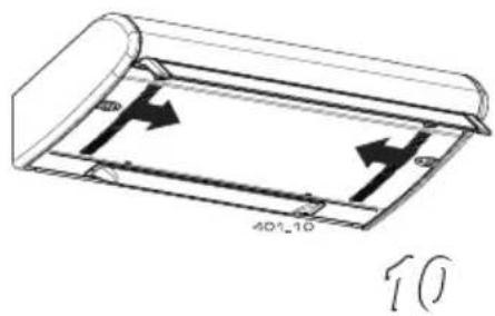
text_image
401-10 10
natural_image
Technical line drawing of a mechanical device with two circular components and an inset close-up view (no text or symbols)text_image
0 1 0 1 1 2 3 L M V12
6. WARTUNG
natural_image
Technical line drawing of a mechanical device with internal components and mounting bracket (no text or symbols)natural_image
Diagram of concentric circles with a small object inside, no text or symbols present14
6.3 - Pflege
natural_image
Technical line drawing of a mechanical device with internal components and ventilation grilles (no text or symbols)natural_image
Illustration of a hand holding a small object on a screen, with 'ZZ' text visible (no other text or symbols)natural_image
Technical line drawing of a curved mechanical component with dimension annotations (no readable text or symbols)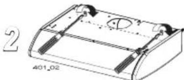
natural_image
Technical line drawing of a mechanical housing or enclosure with mounting flanges and internal components (no text or symbols)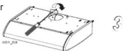
natural_image
Technical line drawing of a mechanical component with a curved base and central hub (no text or symbols)natural_image
3D technical diagram of a mechanical assembly with mounting base and cylindrical component (no text or symbols)natural_image
Diagram showing a curved line with directional arrow and label '401_09' (no readable text or symbols beyond labels)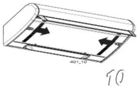
text_image
401.10 10
natural_image
Technical line drawing of a mechanical device with two circular components and an inset close-up showing internal components (no text or symbols)text_image
0 1 1 2 0 1 L M V6. ENTRETIEN
natural_image
Technical line drawing of a mechanical device with internal components and no visible text or symbolsnatural_image
Diagram of concentric circles with a central vertical line and a small circular object inside, labeled '14' at bottom (no text or symbols within the diagram itself)6.3 - Nettoyage
natural_image
Technical line drawing of a mechanical device with internal components and a mesh base (no text or symbols)| Ampoule | Absorption (W) | Culot Voltage (V) Dimensions (mm) Code ILCOS | |||
 | 4 E14 220-240 107 x 37 | DRBB/F-4-220-240-E14-35/100 | |||
 | 5 GU10 230 52 x 50 | DRPAR-5/840-220/240-GU10-35/36DRPAR-5/830-220/240-GU10-35/36 | |||
1-2. CONSIGLI E SUGGERIMENTI
INSTALLAZIONE
text_image
Diagram illustrating shopping order with a shopping cart icon and two circular insets showing a person moving through a cart, labeled 'W'.natural_image
Illustration of a hand holding a small object on a tablet screen, with 'ZZ' text visible (no other text or symbols)natural_image
Technical line drawing of a curved mechanical component with dimension annotations (no readable text or symbols)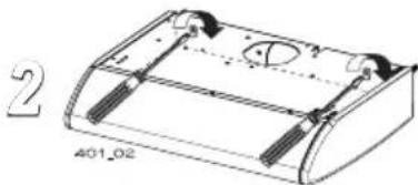
natural_image
Technical line drawing of a mechanical component with mounting holes and internal features (no text or symbols)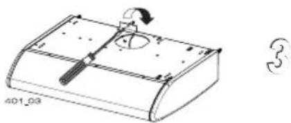
natural_image
Technical line drawing of a mechanical component with no visible text or symbolsnatural_image
3D technical diagram of a mechanical assembly with mounting base and cylindrical component (no text or symbols)3.4 - Connessione aspirante o filtrante
natural_image
Diagram showing a door with an upward arrow and a numbered label '401_08' (no readable text or symbols beyond labels)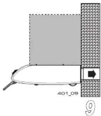
natural_image
Diagram showing a curved line with a shaded area and a brick wall, no text or symbols present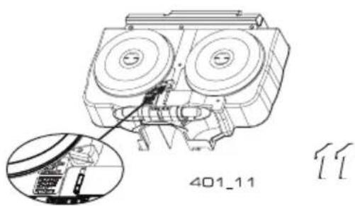
natural_image
Technical line drawing of a mechanical assembly with two circular components and a close-up inset showing internal components (no text or symbols)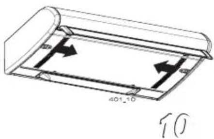
text_image
401_10 10text_image
0 1 0 1 1 2 3 L M V12
6. MANUTENZIONE
natural_image
Technical line drawing of a mechanical device with internal components and a circular component (no text or symbols)natural_image
Simple line drawing of concentric circles with a central dot and a small sphere at the bottom (no text or symbols)6.3 - Pulizia
natural_image
Technical line drawing of a mechanical device with internal components and a mesh base (no text or symbols)| Lampada Assorbimento (W) Attacco | Voltaggio (V) Dimensione (mm) | Codice ILCOS | |
 | 4 E14 220-240 107 x 37 | DRBB/F-4-220-240-E14-35/100 | |
 | 5 GU10 230 52 x 50 | DRPAR-5/840-220/240-GU10-35/36DRPAR-5/830-220/240-GU10-35/36 |
1-2. RECOMMENDATIONS AND SUGGESTIONS
INSTALLATION
- The Instructions for Use apply to several versions of this appliance. Accordingly, you may find descriptions of individual features that do not apply to your specific appliance.
- The manufacturer will not be held liable for any damages resulting from incorrect or improper installation.
- The minimum safety distance between the cooker top and the extractor hood is 650 mm (some models can be installed at a lower height, please refer to the paragraphs on working dimensions and installation).
- Check that the mains voltage corresponds to that indicated on the rating plate fixed to the inside of the hood.
- For Class I appliances, check that the domestic power supply guarantees adequate earthing. Connect the extractor to the exhaust flue through a pipe of minimum diameter 120 mm. The route of the flue must be as short as possible.
- Do not connect the extractor hood to exhaust ducts carrying combustion fumes (boilers, fireplaces, etc.).
- If the extractor is used in conjunction with non-electrical appliances (e.g. gas burning appliances), a sufficient degree of aeration must be guaranteed in the room
in order to prevent the backflow of exhaust gas. The kitchen must have an opening communicating directly with the open air in order to guarantee the entry of clean air. When the cooker hood is used in conjunction with appliances supplied with energy other than electric, the negative pressure in the room must not exceed 0,04 mbar to prevent fumes being drawn back into the room by the cooker hood.
- In the event of damage to the power cable, it must be replaced by the manufacturer or by the technical service department, in order to prevent any risks.
- If the instructions for installation for the gas hob specify a greater distance specified above, this has to be taken into account. Regulations concerning the discharge of air have to be fulfilled.
- Use only screws and small parts in support of the hood.
Warning: Failure to install the screws or fixing device in accordance with these instructions may result in electrical hazards.
- Connect the hood to the mains through a two-pole switch having a contact gap of at least 3 mm.
USE
- The extractor hood has been designed exclusively for domestic use to eliminate kitchen smells.
- Never use the hood for purposes
other than for which it has been designed.
- Never leave high naked flames under the hood when it is in operation.
- Adjust the flame intensity to direct it onto the bottom of the pan only, making sure that it does not engulf the sides.
- Deep fat fryers must be continuously monitored during use: overheated oil can burst into flames.
- Do not flambè under the range hood; risk of fire.
- This appliance can be used by children aged from 8 years and above and persons with reduced physical, sensory or mental capabilities or lack of experience and knowledge if they have been given supervision or instruction concerning use of the appliance in a safe way and understand the hazards involved. Children shall not play with the appliance. Cleaning and user maintenance shall not be made by children without supervision.
- “CAUTION: Accessible parts may become hot when used with cooking appliances.”
MAINTENANCE
- The symbol on the product or on its packaging indicates that this product may not be treated as household waste. Instead it shall be handed over to the applicable collection point for the recycling of electrical and electronic equipment. By ensuring this product
is disposed of correctly, you will help prevent potential negative consequences for the environment and human health, which could otherwise be caused by inappropriate waste handling of this product. For more detailed information about recycling of this product, please contact your local city office, your household waste disposal service or the shop where you purchased the product.
- Switch off or unplug the appliance from the mains supply before carrying out any maintenance work.
- Clean and/or replace the Filters after the specified time period (Fire hazard).
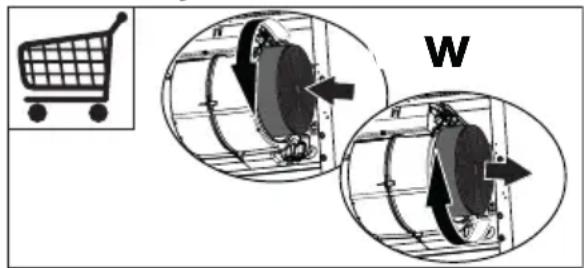
- The Activated charcoal filter is not washable and cannot be regenerated, and must be replaced approximately every 4 months of operation, or more frequently for particularly heavy usage (W). A long life filter, washable and reusable, can be used, as an accessory, for some models.
text_image
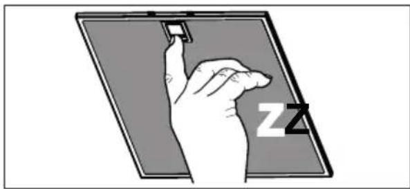
Diagram illustrating shopping order with a shopping cart icon and two circular insets showing mechanical components with arrows, labeled 'W'.- The Grease filters must be cleaned every 2 months of operation, or more frequently for particularly heavy usage, and can be washed in a dish-washer (Z).
natural_image
Illustration of a hand holding a small object on a screen, with 'ZZ' text visible (no other text or symbols)- Control lights, if present.
- Clean the hood using a damp cloth and a neutral liquid detergent.
3. INSTALLATION
3.1 - Fitting the splashback
Before installing the hood it is possible to fit the splash-back provided, if required.
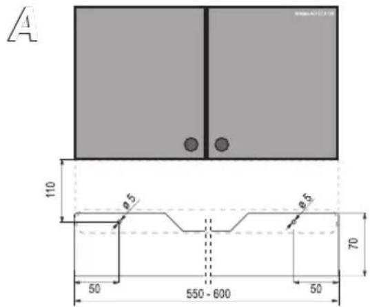
- Mark the holes required to fix it to the wall, as shown in fig. A.
- Drill the wall (2 holes ∅ 5mm) and insert the wall plugs.
- Fix the splashback to the wall using the two 3x35 screws (provided).
3.2 - Wall installation
The hood can be supplied with two different fixing kits:
a) screws, plugs and safety square.
b) screws, plugs and metal brackets.
1 - Fixing with screws
Using the cardboard template, mark and drill the holes on the wall (2 holes ∅ 8 mm see instructions on the template), insert the plugs in the holes, tighten both 4,2 x 44,4 screws(supplied) leaving about 5 mm un-screwed, hook the hood onto the screws (fig. 1) and secure tightly from inside (fig. 2). Mount the safety square (supplied) above the hood (fig. 3).
text_image
A 110 8.5 8.5 70 50 550 - 600 50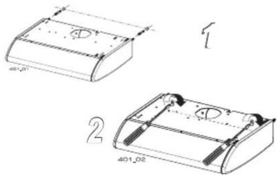
text_image
401.01 401.02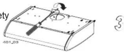
natural_image
Technical line drawing of a mechanical component with a handle and circular opening (no text or symbols)3.3 - Wall unit installation
Using the cardboard template, mark and drill the bottom of the wall unit, (see instructions on the template).
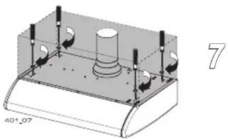
Fasten the hood from inside the unit using four screws 4,2 x 44,4 (supplied) (fig.7). For suction hoods, the wall unit must be drilled to allow for the air discharge duct. Filter hoods do not require this type of drilling operation since the air is recycled into the room through vents situated on the front of the hood.
natural_image
3D technical diagram of a mechanical assembly with mounting base and cylindrical component (no text or symbols)3.4 - Connecting suction or filter hoods
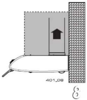
1 - Connecting suction hoods (air is discharged into the atmosphere) The hood comes with two air outlets, a plastic cover fitted in the rear hole and a flange to be fitted according to the solution chosen: top discharge (fig. 8), rear discharge (fig. 9). In case of installation with rear discharge, fit the plastic cover in the top hole and the flange in the rear hole. Using a pipe ∅ 100 o 120 mm, connect the air discharge flange to the external discharge duct. Open the grid panel by pressing inwards on the knobs (fig. 10), check that the lever (hood with one motor) or the handle (hood with two motors) points to the ducting mode position (fig. 11), remove the charcoal filter, if any, by turning the handle anti-clockwise (see par.3.3 2 part 2°).
Respect warning 2.1
2 - Connecting filter hoods (air is filtered and recirculated inside the room) Open the grid panel, check that the lever (hood with one motor) or the handle (hood with two motors) points to the filter mode position (fig. 11), insert the charcoal filter (see par.3.3 2 part 2°).
text_image
401_08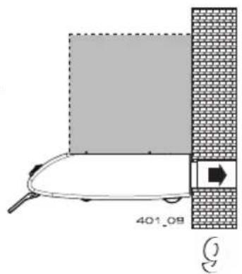
text_image
401.08
natural_image
Technical line drawing of a mechanical device with two circular components and an inset close-up showing internal components (no text or symbols)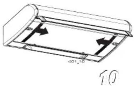
text_image
401_10 103.5 - Electrical connection and working test
Once the electrical connection has been completed, check that the worktop illumination, motor and speeds work properly.
4. SAFETY WARNINGS
(It is most important that all the warnings shown in paragraph 2 of the Installation Instructions are strictly observed). Moreover, special attention must be paid to the following warnings during the use and maintenance of the cooker hood:
4.1- The grease filters and the charcoal filters should be cleaned or replaced as recommended by the manufacturer or more frequently if the hood is used consistently (more than 4 hours per day).
4.2- When using a gas hob in connection with the cooker hood never leave the burners of the hob uncovered while the hood is in use or when the pans have been removed. Switch off the gas before removing the pan or for just short periods and never leave the hob unattended.
4.3- Always ensure that the appliance is kept at the correct intensity to prevent the flame from licking round from the bottom of the pan; this will save energy and will avoid a dangerous concentration of heat.
4.4 - Always ensure that the appliance is used in accordance with the manufacturer's instructions for the removal of contaminated odours during cooking.
5. USE
L Light Switches the lighting system on and off.
M Motor Switches the extractor motor on and off.
V Speed Sets the operating speed of the extractor.
-
Low speed, used for a continuous and silent air change in the presence of light cooking vapour.
-
Medium speed, suitable for most operating conditions given the optimum treated air flow/noise level ratio.
-
Maximum speed, used for eliminating the highest cooking vapour emission, including long periods.

text_image
0 1 0 1 1 2 3 L M V12
6. MAINTENANCE
Regular maintenance will ensure good performance and extend the working life of the hood. Special attention should be taken to the grease filters and, for the filter hoods only, to the charcoal filters.
6.1 - Metal grease filters
1 - Cleaning
These filters need to be washed with ordinary household detergent every 2 months maximum. Thanks to their reduced dimensions, they can also be washed in the dishwasher.
2 - Removing the filter
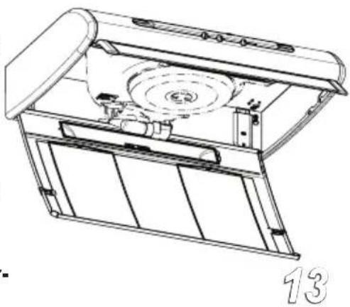
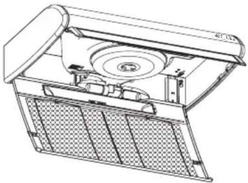
Open the grid panel, remove the steel wire clips and the grease filter (fig. 13). Make sure that the filter is dry before replacing it, close the grid panel.
WARNING : Respect replacement and maintenance schedules recommended in order to avoid fire hazards caused by over-saturated filters.
natural_image
Technical line drawing of a mechanical device with internal components and a circular component (no text or symbols)6.2 - Charcoal filters
1 - How they work
Charcoal filters can absorb smells and odours until they are saturated. They cannot be washed or recycled and so they should be replaced at least every 4 months or more frequently if the hood is heavily used.
2 - Replacement:
Open the grid panel, replace the charcoal filter by turning the locking handle anti-clockwise for removing and clockwise for replacing (fig. 14). Close the grid panel.

natural_image
Simple line drawing of concentric circles with a central dot and a small sphere at the center (no text or symbols)6.3 - Cleaning
When cleaning the hood:
- Never use a wet cloth or sponge, or running water.
- Never use thinners or products containing alcohol, as they might damage the paintwork.
- Never use abrasive cleaning materials, in particular when cleaning stainless steel surfaces.
It is recommended to use a damp cloth and mild liquid household cleaner.
6.4 - Lighting
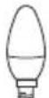
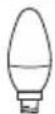
If a lamp fails to function at any time, open the metal grille panel and check that the lamp is fully screwed into the holder.A
When changing the lamp, an identical replacement must be fitted to ensure a safe working of the hood.
natural_image
Technical line drawing of a mechanical device with internal components and mounting bracket (no text or symbols)| Lamp Power (W) Socket Voltage (V) Dimension (mm) ILCOS Code | |||||
| [5WSX] | 4 E14 220-240 107 x 37 | DRBB/F-4-220-240-E14-35/100 | |||
 | 5 GU10 230 52 x 50 | DRPAR-5/840-220/240-GU10-35/36DRPAR-5/830-220/240-GU10-35/36 | |||
CE
