
VT6367 - Compressor Campbell Hausfeld - Free user manual and instructions
Find the device manual for free VT6367 Campbell Hausfeld in PDF.

User questions about VT6367 Campbell Hausfeld
0 question about this device. Answer the ones you know or ask your own.
Ask a new question about this device
Download the instructions for your Compressor in PDF format for free! Find your manual VT6367 - Campbell Hausfeld and take your electronic device back in hand. On this page are published all the documents necessary for the use of your device. VT6367 by Campbell Hausfeld.
USER MANUAL VT6367 Campbell Hausfeld
CH CAMPBELL HAUSFELD®
Portable Air Compressor
Operating Instructions and Parts Manual
natural_image
Exterior view of a black Campbell Hausfeld air compressor on a four-tire chassis (no visible text or symbols beyond branding)Models: VT6367 and VT6358

CAMPBELL HAUSFELD.
Please read and save these instructions. Read carefully before attempting to assemble, install, operate or maintain the product described.
Protect yourself and others by observing all safety information. Failure to comply with instructions could result in personal injury and/or property damage! Retain instructions for future reference.
REMINDER: Keep your dated proof of purchase for warranty purposes! Attach it to this manual or file it for safekeeping.
For parts, product & service information visit www.campbellhausfeld.com
Model #: ____
Serial #: ____
Purchase Date: ____
Campbell Hausfeld
100 Production Drive
Harrison, Ohio 45030
BEFORE YOU BEGIN
Introduction
Air compressor units are intended to provide compressed air to power pneumatic tools, operate spray guns and supply air for pneumatic valves and actuators. The pumps supplied with these units have oil lubricated bearings. A small amount of oil carryover is present in the compressed air stream. Applications requiring air free of oil vapor should have the appropriate filters installed. The air compressor units are to be mounted per the instructions provided on a solid floor. Any other use of these units will void the warranty and the manufacturer will not be responsible for problems or damages resulting from such misuse.
| QUICK REFERENCE |
| RECOMMENDED OIL (2 OPTIONS) |
| Single viscosity SAE30 ISO100 nondetergent compressor oil. Part number ST125303AV (0.5 qt) or ST126701AV (4 qt). |
| 10W30 synthetic oil such as Mobile 1 or CE0032 (1 qt). |
| OIL CAPACITY |
| Approximately 8.5 oz. |
UNPACKING
⚠️ CAUTION Do not lift or move unit without appropriately rated equipment. Be sure the unit is securely attached to lifting device used. Do not lift unit by holding onto tubes or coolers. Do not use unit to lift other attached equipment.
After unpacking the unit, inspect carefully for any damage that may have occurred during transit. Check for loose, missing or damaged parts. Check to be sure all supplied accessories are enclosed with the unit. In case of questions, damaged or missing parts, please visit www.campbellhausfeld.com for customer assistance.
Do damage unit if damaged during shipping, handling or use. Damage may result in bursting and cause injury or property damage.
GENERAL SAFETY INSTRUCTIONS
Safety Guidelines
This manual contains information that is very important to know and understand. This information is provided for SAFETY and to PREVENT EQUIPMENT PROBLEMS. To help recognize this information, observe the following symbols.
A DANGER
imminently hazardous situation which, if not avoided, WILL result in death or serious injury.
WARNING
Warning indicates a potentially hazardous situation which, if not avoided, COULD result in ath or serious injury.
CAUTION
Caution indicates a potentially hazardous situation which, if not avoided, MAY result in minor or moderate injury.
NOTICE
Notice indicates important information, that if not followed, may cause damage to equipment.
IMPORTANT: Information that requires special attention.
Safety Symbols
The following Safety Symbols appear throughout this manual to alert you to important safety hazards and precautions.

Wear Eye and Mask Protection
Read Manual First

Risk of Fire

Risk of Moving Parts

Risk of Hot Parts
Risk of Explosion

Risk of Fumes
Risk of Pressure

Risk of Shock
California Proposition 65
WARNING
This product or its power cord may contain chemicals known to the State of California to cause cancer and birth defects or other reproductive harm. Wash hands after
handling.
You can create clust WARNING
when you cut, sand, drill or grind materials such as wood, paint, metal, concrete, cement, or other masonry. This dust often contains chemicals known to defects, or other reproductive harm. Wear protective gear.
cause cancer, birth defects, or other reproductive harm. Wear protective gear.
Important Safety Information
Please read and save these instructions. Read carefully before attempting to assemble, install, operate or maintain the product described. Protect yourself and others by observing all safety information. Failure to comply with instructions could result in personal injury and/or property damage! Retain instructions for future reference.
This manual contains important safety, operational and maintenance information. If you have any questions, please visit www.campbellhausfeld.com for customer assistance.
Since the air compressor and other components (material pump, spray guns, filters, lubricators, hoses, etc.) used make up a high pressure pumping system, the following safety precautions must be observed at all times:
DANGER
BREATHABLE AIR WARNING
This compressor/pump is not equipped and should not be used "as is" to supply breathing quality air. For any application of air for human consumption, the air compressor/pump will need to be fitted with suitable in-line safety and alarm equipment. This additional equipment is necessary to properly filter and purify the air to meet minimal specifications for Grade D breathing as described in Compressed Gas Association Commodity Specification G 7.1, OSHA 29 CFR 1910. 134, and/or Canadian Standards Associations (CSA).
DISCLAIMER OF WARRANTIES
In the event the compressor is used for the purpose of breathing air application and proper in-line safety and alarm equipment is not simultaneously used, existing warranties shall be voided, and the manufacturer disclaims any liability whatsoever for any loss, personal injury or damage.
General Safety
- Read all manuals included with this product carefully. Be thoroughly familiar with the controls and the proper use of the equipment.
- Follow all local electrical and safety codes as well as the United States National Electrical Codes (NEC) and Occupational Safety and Health Act (OSHA).
- Only persons well acquainted with these rules of safe operation should be allowed to use the compressor.
- Keep visitors away and NEVER allow children in the work area.
- Wear safety glasses and use hearing protection when operating the unit.
- Do not stand on or use the unit as a handhold.
- Before each use, inspect compressed air system and electrical components for signs of damage, deterioration, weakness or leakage. Repair or replace defective items before using.
- Check all fasteners at frequent intervals for proper tightness.

⚠ WARNING Motors, electrical equipment and controls can cause electrical arcs that will ignite a flammable gas or vapor. Never operate or repair in or near a flammable gas or vapor. Never store flammable liquids or gases in the vicinity of the compressor.
⚠ WARNING Never operate compressor without a beltguard. This unit can start automatically without warning. Personal injury or property damage could occur from contact with moving parts.
- Do not wear loose clothing or jewelry that will get caught in the moving parts of the unit.
CAUTION Compressor parts may be hot even if the unit is stopped.
- Keep fingers away from a running compressor; fast moving and hot parts will cause injury and/or burns.
- If the equipment should start to vibrate abnormally, STOP the engine/motor and check immediately for the cause. Vibration is generally an indication of trouble.
- To reduce fire hazard, keep engine/motor exterior free of oil, solvent, or excessive grease.
⚠ WARNING An ASME code safety relief valve with a setting no higher than the Maximum Allowable Working Pressure (MAWP) of the tank MUST be installed in the air lines or in the tank for this compressor. The ASME safety valve must have sufficient flow and pressure ratings to protect the pressurized components from bursting. The flow rating can be found in the parts manual. The safety valve in the intercooler does not provide system protection.
⚠ WARNING Maximum operating pressure is 135 psi for single stage compressors. Do not operate with pressure switch or pilot valves set higher than 135 psi (single stage).
- Never attempt to adjust ASME safety valve. Keep safety valve free from paint and other accumulations.
Important Safety Information (Continued)
⚠ WARNING
Never attempt to repair or modify a tank! Welding, drilling or any other modification will weaken the tank resulting in damage from rupture or explosion. Always replace worn, cracked
or damaged tanks.
NOTICE
Drain liquid from tank daily.
- Tanks rust from moisture build-up, which weakens the tank. Make sure to drain tank regularly and inspect periodically for unsafe conditions such as rust formation and corrosion.
- Fast moving air will stir up dust and debris which may be harmful. Release air slowly when draining moisture or depressurizing the compressor system.
Spraying Precautions
Do not spray flammable materials in vicinity of open flame or near ignition sources including the compressor unit.
- Do not smoke when spraying paint, insecticides, or other flammable substances.
- Use a face mask/respirator when spraying and spray in a well ventilated area to prevent health and fire hazards.
- Do not direct paint or other sprayed material at the compressor. Locate compressor as far away from the spraying area as possible to minimize overspray accumulation on the compressor.
- When spraying or cleaning with solvents or toxic chemicals, follow the instructions provided by the chemical manufacturer.

Save These Instructions Do Not Discard
The DANGER, WARNING, CAUTION, and NOTICE notifications and instructions in this manual cannot cover all possible conditions and situations that may occur. It must be understood by the operator that caution is a factor which cannot be built into this product, but must be supplied by the operator.
Getting To Know Your Compressor
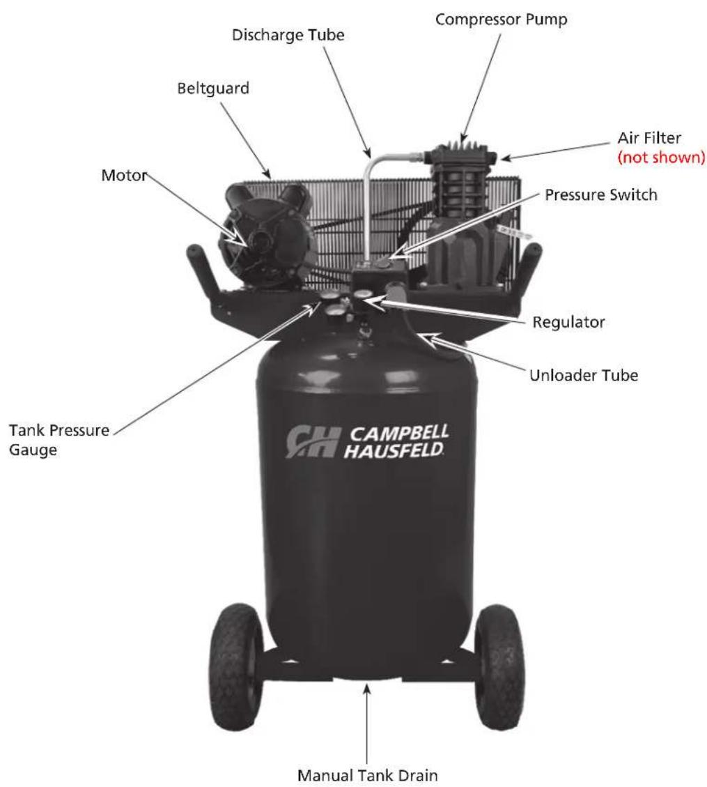
text_image
Discharge Tube Beltguard Motor Tank Pressure Gauge CAMPBELL HAUSFELD. Compressor Pump Air Filter (not shown) Pressure Switch Regulator Unloader Tube Manual Tank DrainFigure 1 - Vertical Unit Identification
SPECIFICATIONS
| VT6358 and VT6367 | |
| Motor HP 2 | |
| Power 120V/240V | |
| Phase 1 (single) | |
| Displacement CFM 7.2 | |
| Air Delivery CFM @ 90 PSI 5.5 | |
| Air Delivery CFM @ 135 PSI 4.9 | |
| Max PSI 135 | |
| Pump RPM 1020 | |
| Tank Capacity 30 gallon | |
| Unit Weight 178 lbs. | |
| Amp Draw | 15A / 7.5A |
| Max Duty Cycle | 75% |
| Tank Outlet | 1/4 NPT |
DIMENSIONS
| VT6358 and VT6367 | |
| Length | 23 in. |
| Width | 24 in. |
| Height | 46 in. |
INSTALLATION INSTRUCTIONS
Grounding
This product must be grounded. In the event of an electrical short circuit, grounding reduces the risk of electric shock by providing an escape wire for the electric current. This product is equipped with a cord having a grounding wire with an appropriate grounding plug. The plug must be plugged into an outlet that is properly installed and grounded in accordance with all local codes and ordinances. Do not use grounding adapter.
WARNING
Risk of electric shock. Improper use of grounding plug can result in a risk of electrical shock. Plug must be plugged into an outlet that is properly installed and grounded in accordance with local
codes and ordinances by a qualified electrician.
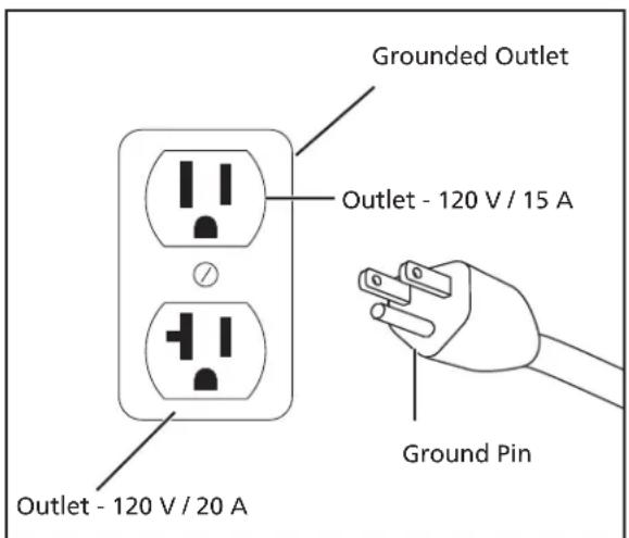
This product comes from the factory ready for use on a nominal 120 volt circuit and has a grounding plug similar to the plug illustrated in Figure 2. If the listed conditions cannot be met or if nuisance tripping of the current protection device occurs, it may be possible to operate the compressor from a 120 volt 20 amp circuit. See Figure 2.
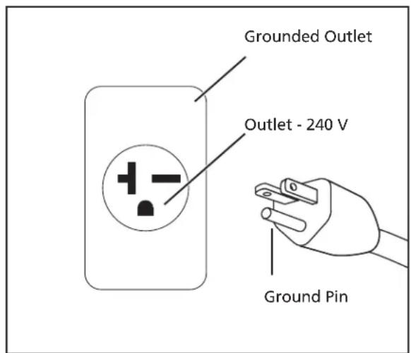
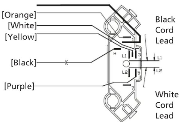
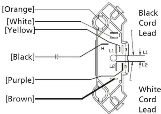
Check motor data plate for 240 volt compatibility. A 240 volt unit must be operated on a 240 volt circuit. The cord must only plug into a 240 volt grounded outlet and may require a new cord and plug. See Figure 3. This product may be modified to operate at 240V. To do so, a 240V power cord needs to be purchased and installed on the unit and wired into the pressure switch just like the 120V cord. The panel on the back of the motor needs to be opened and the flag terminals need to be moved so that the brown wire that is on terminal #1 is on terminal #7 and the white wire that is on terminal #3 needs to be moved to terminal #1 (where the brown wire was originally). See Figure 4.
WARNING
All wiring and electrical connections should be performed by a qualified electrician. Installation must be in accordance with local codes and national electrical codes. If not properly grounded, the electrical shock, particularly when used in damp locations, in proximity of plumbing, outdoors.
this tool can cause an electrical shock, particularly when used in damp locations, in proximity of plumbing, outdoors.
WARNING
Installation of grounding plug can result in electric shock. When repair or replacement of the cord or plug is required, do not connect the grounding wire to either flat blade terminal. The
wire with insulation having an outer surface that is green with or without yellow stripes is the grounding wire. Never connect green (or green and yellow) wire to a live terminal.
text_image
Grounded Outlet Outlet - 120 V / 15 A Outlet - 120 V / 20 A Ground PinFigure 2 - 120V
text_image
Grounded Outlet Outlet - 240 V Ground PinFigure 3 - 240V
INSTALLATION INSTRUCTIONS (CONTINUED)
Use only a 3-wire extension cord that has a 3-blade grounding plug and a 3-slot receptacle that accepts the plug on the product. Make sure your extension cord is not damaged. When using an extension cord, be sure to use one heavy enough to carry the current your product draws. For lengths less than 25 ft. 16-3 AWG extension cords shall be used. An undersized cord results in a drop in the voltage and loss of power and overheating. (NOTICE: Table below shows the correct size to use depending on cord length. When in doubt, use the next heavier gauge. The smaller the gauge number, the heavier the cord.)
Use of an extension cord may cause excess heat to motor. This could lead to tripped breaker (at electrical panel) or tripped thermal overload (on compressor motor). If this occurs, eliminate extension cord and plug compressor directly into electrical outlet. Avoid using extension cords; use longer air hose(s) instead.
Check with a qualified electrician or serviceman when the grounding instructions are not completely understood, or when in doubt as to whether the product is properly grounded. Do not modify the plug provided; if it does not fit the outlet, have the proper outlet installed by a qualified electrician. Only connect the product to an outlet having the same configuration as the plug. Do not use an adapter with this product.
| Amp Rating Range | Voltage Cord Length in Feet | |||||||||
| 120V | 25 ft. | 50 ft. | 100 ft. | 150 ft. | 200 ft. | 250 ft. | 300 ft. | 400 ft. | 500 ft. | |
| 14-16 | 16 12 10 | 8 6 6 | 4 | 4 2 | ||||||
120V Configuration
text_image
[Orange] [White] [Yellow] [Black] [Purple] Black Cord Lead H L1 3 L2 5 7 L1 L2 White Cord Lead240V Configuration
text_image
[Orange] [White] [Yellow] [Black] [Purple] [Brown] Black Cord Lead L1 H L2 3 5 7 L1 L2 White Cord LeadFigure 4 - 120V and 240 Configuration
INSTALLATION INSTRUCTIONS (CONTINUED)
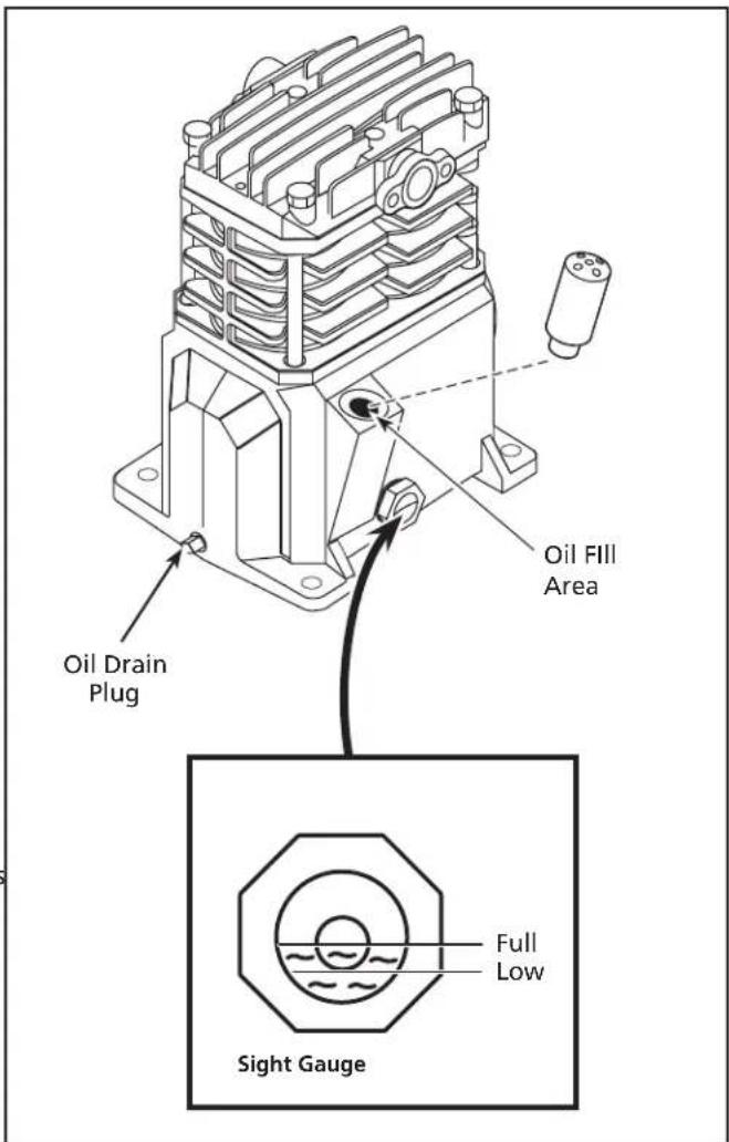
Lubrication
Refererating compressor, ensure oil is filled to the center of the sight gauge (see figure 5).
Using a plotype of oil may shorten pump life and damage valves.
RECOMMENDED OIL (2 OPTIONS)
Single viscosity SAE30 ISO100 nondetergent compressor oil. Part number ST125303AV (0.5 qt) or ST126701AV (4 qt).
10W30 synthetic oil such as Mobile 1 or CE0032 (1 qt).
OIL CAPACITY
Approximately 8.5 oz.
Remove cap from oil fill opening. Install breather (found in parts bag with this manual). Check oil level. See specification label on compressor pump for the proper oil capacity and oil type. All lubricated compressor pumps discharge some condensed water and oil with the compressed air. Install appropriate water/oil removal equipment and controls as necessary for the intended application.
Do not use regular automotive oil. Additives in regular motor oil can cause valve deposits and reduce pump life. For maximum pump life, drain and replace oil after the first fifty (50) hours of operation. Then perform oil changes every three (3) months.
text_image
Oil Drain Plug Oil Fill Area Full Low Sight GaugeFigure 5 - Lubrication
OPERATING INSTRUCTIONS
All lubricated compressor pumps discharge some condensed water and oil with the compressed air. Install appropriate water/oil removal equipment and controls as necessary for the intended application.
Failure to install appropriate water/oil removal equipment may result in damage to machinery or workpiece.
Start-up / Break-in Procedure
Risk WARNING Injury. Do not attach air tools to open end of the hose until start-up is completed and the unit checks okay.
WARNING
Risk of Personal Injury. Never disconnect threaded joints with pressure in tank!
- Check oil level per the Lubrication Section of this manual.
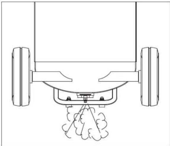
- Open the bottom tank drain valve (see Figure 6). Turn outlet valve to open air flow.
- Plug unit in.
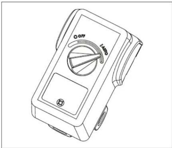
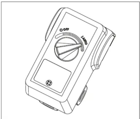
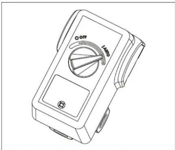
- Move pressure switch to the AUTO position to run the unit (see Figure 7).
- Run the unit for thirty (30) minutes at zero (0) psi (under no load) to break in pump parts.
- Move the pressure switch lever or knob to OFF and turn tank drain valve to shut off air flow. The compressor is now ready for use.
- Change oil after first fifty (50) hours of operation. Then perform oil changes every three (3) months or two hundred (200) hours of run time, whichever comes first.
natural_image
Technical line drawing of a vehicle suspension system with two wheels and a spray nozzle (no text or symbols)Figure 6
Compressor Use
It is extremely important to operate the compressor in a clean, well-ventilated area where the surrounding air temperature will not be more than 100^ F. Do not locate the compressor air inlet near steam, paint spray, sandblast areas or any other source of contamination.
natural_image
Line drawing of a handheld electronic device with labeled buttons (OFF, AUTO) and no readable text or symbols beyond the label.Figure 7
On/Off Cycling of Compressor
Pis of WARNING drain tank every day to prevent corrosion and possible injury due to tank damage. Do not operate drain with more than 40 psi in tank or drain valve may be damaged. Drain tank of moisture daily using the drain valve in the bottom of the tank.
NOTICE
Unit care and maintenance. Drain liquid from tank daily.
In the AUTO position, the compressor pumps air into the tank. When a shut-off (preset "cut-out") pressure is reached, the compressor automatically shuts off.
If the compressor is left in the AUTO position and air is depleted from the tank by use of a tire chuck, tool, etc., the compressor will restart automatically at its preset "cut-in" pressure. When a tool is being used continuously, the compressor will cycle on and off automatically.
In the OFF position, the compressor will not operate.
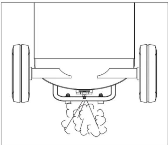
Drain Tank. Disconnect, tag, unplug and lock out power source; release pressure. Drain moisture from tank by opening drain valve underneath tank (See Figure 8).
natural_image
Technical line drawing of a vehicle suspension system with two wheels and a central car component (no text or symbols)Figure 8
MOISTURE IN COMPRESSED AIR
Moisture in compressed air will form into droplets as it comes from an air compressor pump. When humidity is high or when a compressor is in continuous use for an extended period of time, this moisture will collect in the tank. When using a paint spray or sandblast gun, this water will be carried from the tank through the hose, and out of the gun as droplets mixed with the spray material.
IMPORTANT: This condensation will cause water spots in a paint job, especially when spraying other than water based paints. If sandblasting, it will cause the sand to cake and clog the gun, rendering it ineffective. A filter in the air line, located as near to the gun as possible, will help eliminate this moisture.
TROUBLESHOOTING GUIDE
SYMPTOM POSSIBLE CAUSE(S) CORRECTIVE ACTION
| Low discharge pressure 1. Air demand exceeds pump capacity 1. Reduce air demand or use a compressor with more capacity. | ||
| 2. Restricted air intake 2. Clean or replace the air filter element. | ||
| 3. Air leaks (fittings, tubing on compressor, or plumbing outside of system) | 3. Listen for escaping air. Apply soap solution to all fittings and connections. Bubbles will appear at points of leakage. Tighten or replace leaking fittings or connections. Use pipe thread sealant. | |
| 4. Blown gaskets 4. Replace any gaskets proven faulty on inspection. | ||
| 5. Leaking or damaged valves 5. Remove head and inspect for valve breakage, misaligned valves, damaged valve seats, etc. Replace defective parts and reassemble. | ||
| time the head is removed. | ||
| Excessive noise (knocking) | 1. Loose motor pulley or flywheel | 1. Tighten pulley/flywheel clamp bolts and set-screws. |
| 2. Loose fasteners on pump or motor | 2. Tighten fasteners. | |
| 3. Lack of oil in crankcase | 3. Check for proper oil level; if low, check for possible damage to bearings. Dirty oil can cause excessive wear. | |
| 4. Worn connecting rod | 4. Replace connecting rod. Maintain oil level and change oil more frequently. | |
| 5. Worn piston pin bores | 5. Remove piston assemblies from the compressor and inspect for excess wear. Replace excessively worn piston pin or pistons, as required. Maintain oil level and change oil more frequently. | |
| 6. Piston hitting the valve plate | 6. Remove the compressor head and valve plate and inspect for carbon deposits or other foreign matter on top of piston. Replace head and valve plate using new gasket. See Lubrication section for recommended oil. | |
| 7. Noisy check valve in compressor system | 7. Replace check valve. | |
| pressure in tank. | ||
| Large quantity of oil in the discharge airNOTE: In an oil-lubed compressor there will always be a small amount of oil in the air stream. | 1. Worn piston rings | 1. Replace with new rings. Maintain oil level and change oil more frequently. |
| 2. Compressor air intake restricted | 2. Clean or replace filter. Check for other restrictions in the intake system. | |
| 3. Excessive oil in compressor | 3. Drain down to full level. | |
| 4. Wrong oil viscosity | 4. Use Mobil 1® 10W-30 or full synthetic. | |
| Water in discharge air/tank | Normal operation. The amount of water increases with humid weather | 1. Drain tank more often. At least daily. |
| 2. Add a filter to reduce the amount of water in the air line. | ||
| Motor hums and runs slowly or not at all | 1. Low voltage | 1. Check incoming voltage. It should be approximately 230 volts. Motor will not run properly on 208 volts. Low voltage could be due to wires (from electrical source to compressor) being too small in diameter and / or too long. Have a qualified electrician check these conditions and make repairs as needed. |
| 2. Use of extension cord | 2. Do not use an extension cord. Use longer air hose with larger diameter. | |
| 3. Too many devices on same circuit | 3. Limit the circuit to the use of compressor only | |
| 4. Loose electrical connections | 4. Check all electrical connections. | |
| 5. Malfunctioning pressure switch - contacts will not close | 5. Replace pressure switch. | |
| 6. Malfunctioning check valve | 6. Replace check valve. | |
TROUBLESHOOTING GUIDE (CONTINUED)
SYMPTOM POSSIBLE CAUSE(S) CORRECTIVE ACTION
| Motor hums and runs slowly or not at all (Continued) | 7. Defective unloader valve on pressure switch8. Defective motor capacitor(s) 8. Replace capacitor(s).9. Defective motor 9. Replace motor. | 7. Replace unloader valve. |
| Reset mechanism cuts out repeatedly or circuit breaker trips repeatedly | 1. Lack of proper ventilation/room temperature too high2. Too many devices on same circuit 2. Limit the circuit to the use of only the air compressor.3. Restricted air intake 3. Clean or replace filter element.4. Loose electrical connection 4. Check all electrical connections.5. Pressure switch shut-off pressure set too high6. Malfunctioning check valve 6. Replace check valve.7. Defective unloader valve on pressure switch8. Defective motor capacitor(s) 8. Replace capacitor(s).9. Malfunctioning motor | 1. Move compressor to well-ventilated area.1. Do not disassemble check valve with air pressure in tank.7. Replace unloader valve.9. Replace motor. |
| Tank does not hold pressure when compressor is off and the shut off valve is closed | 1. Air leaks (fittings, tubing on compressor, or plumbing outside system)2. Worn check valve3. Check tank for cracks or pin holes | 1. Check all connections with soap and water solution. Tighten; or remove and apply sealant to threads, then reassemble.2. Replace check valve.3. Replace tank. Never repair a damaged tank. |
| Pressure switch continuously blows air out the unloader valve | Malfunctioning check valve | Replace the check valve if the unloader valve on the pressure switch bleeds off constantly when unit shuts off.4. Do not disassemble check valve with air pressure in tank. |
| Excessive vibration | 1. Loose fasteners on pump or motor2. Belt needs replaced3. Belt alignment | 1. Tighten fasteners.2. Replace with correct size.3. Align flywheel and pulley. |
| Pressure switch does not release air when the unit shuts off | Malfunctioning unloader valve on pressure switch | Replace the unloader valve if it does not release the pressure for a short period of time when the unit shuts off.5. Do not disassemble unloader valve with air pressure in tank. |
MAINTENANCE AND INSPECTION INSTRUCTIONS
WARNING
Disconnect, tag and lock out power source then release all pressure from the system before attempting to install, service, relocate or perform any maintenance.
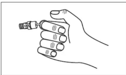
In order to maintain efficient operation of the compressor system, check the air filter and oil level before each use. The ASME safety valve should also be checked daily (see Figure 9). Pull ring on safety valve and allow the ring to snap back to normal position. This valve automatically releases air if the tank pressure exceeds the preset maximum. If air leaks after the ring has been released, or the valve is stuck and cannot be actuated by the ring, the ASME safety valve must be replaced.
WARNING
Do not tamper with the ASME safety valve.
natural_image
Line drawing of a hand holding a small mechanical component (no text or symbols)Figure 9 - ASME Safety Valve
Tank
WARNING
Never attempt to repair or modify a tank! Welding, drilling or any other modification will weaken the tank resulting in damage from rupture or explosion. Always replace worn, cracked
or damaged tanks.
Drain liquid from tank daily.
The tank should be carefully inspected at a minimum of once a year. Look for cracks forming near the welds. If a crack is detected, remove pressure from tank immediately and replace.
Compressor Lubrication
See Installation. Add oil as required. The oil should be changed every three months or after every 200 hours of operation; whichever comes first.
If the compressor is run under humid conditions for short periods of time, the humidity will condense in the crankcase and cause the oil to look creamy. Oil contaminated by condensed water will not provide adequate lubrication and must be changed immediately. Using contaminated oil will damage bearings, pistons, cylinders and rings and is not covered under warranty. To avoid water condensation in the oil, periodically run the compressor with tank pressure near 120 psi for single stage compressors by opening the drain cock or an air valve connected to the tank or hose. Run the pump for an hour at a time at least once a week or more often if the condensation reoccurs.
IMPORTANT: Change oil after first 50 hours of operation.
Air Filter
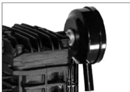
Never run the compressor pump without an intake air filter or with a clogged intake air filter. The air filter element should be checked monthly (see Figure 10). Operating compressor with a dirty filter can cause high oil consumption and increase oil contamination in the discharge air. If the air filter is dirty it must be replaced.
Components
Turn off all power and clean the cylinder head, motor, fan blades, air lines, aftercooler and tank on a monthly basis.
natural_image
Close-up of a mechanical component with gears and shafts (no visible text or symbols)Figure 10 - Air Filter Element
MAINTENANCE AND INSPECTION INSTRUCTIONS (CONTINUED)
Belts
Look to bring the power then release all pressure from the tank to prevent unexpected movement of the unit.
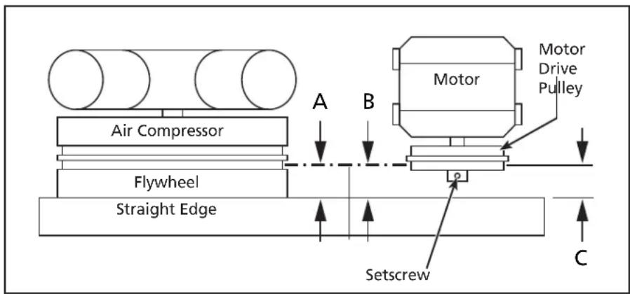
Check belt tension every 3 months. Adjust belt tension to allow 3/8 inch to 1/2 inch deflection with normal thumb pressure. Also, align belts using a straight edge against the face of the flywheel and touching the rim on both sides of the face. The belts should be parallel to this straight edge (see Figure 11). Dimension A should be the same as B and C to ensure proper alignment of the belts.
Slots in the bed-plate allow for sliding the motor back and forth to adjust belt tension.
text_image
Air Compressor Flywheel Straight Edge A B Motor Motor Drive Pulley Setscrew CFigure 11 - Top View
Removing Belt Guard
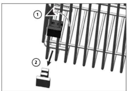
When we are in belt guard front to inspect or replace belts, inspect plastic retaining clips and replace if damaged or if clip can be removed without a tool.
Removing Retaining Clips
- Using crescent wrench on pliers, rotate clip 90°.
- Pull clip out and away from beltguard.
- Reverse process to reinstall after inspecting the clip.
Storage
If compressor is to be stored for a short period of time, make sure that it is stored in a normal position and in a cool protected area.
text_image
Diagram showing a mechanical assembly with labeled parts ① and ②, likely illustrating a gear or rack mechanism.Figure 12
Maintenance Schedule
| OPERATION DAILY MONTHLY 3 MONTHS | |
| Check Safety Valve | ● |
| Drain Tank (see Figure 6) | ● |
| Check Oil Level | ● |
| Clean or Change Air Filter | ● |
| Check Intercooler | ● |
| Clean Unit Components | ● |
| Check Belt Tightness | ● |
| Change Oil (see Figure 5) | ● |
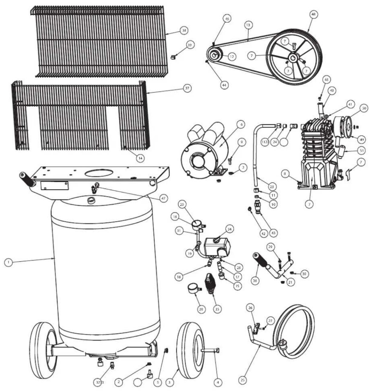
REPAIR PARTS ILLUSTRATION FOR VT6358 AND VT6367
text_image
Technical diagram of an automotive air conditioning system with labeled components and exploded viewsFor Repair Parts, visit www.campbellhausfeld.com to find your local distributor 24 hours a day – 365 days a year
Please provide following information:
- Model number
- Serial number (if any)
- Part description and number as shown in parts list
Ref.
No. Description Part Number Qty
| 1 | TANK, 30 GALLONS AR067500CG 1 | ||
| 2 | SPINLOCK NUT, 5/16 IN.-18 | ST146001AV 1 | |
| 3 | PNUEMATIC WHEEL, 10 IN. | WA006000AV 2 | |
| 4 | AXLE BOLT, 3/8 IN.-16 X 3 IN. | ST084700AV 2 | |
| 5 | FLANGE NUT, 3/8 IN.-16 | ST033500AV 2 | |
| 6 | MOTOR, 2HP 120/240V MC019800SJ 2 | ||
| 7 | COMPRESSOR PUMP | VT482200AJ | 4 |
| 8 | SELF TAPPING SCREW, 5/16 IN.-12 | ST016500AV 1 | |
| 9 | HEX HEAD BOLT, 5/16 IN. -18 X 3/4" | ST016000AV 3 | |
| 10 | RUBBER FERRULE, 1/2 IN. TUBE | ST085200AV 1 | |
| 11 | COMPRESSION NUT, 1/2 IN. | ST033001AV 4 | |
| 12 | MOTOR PULLEY | PU015200AV 4 | |
| 13 | BELT, AX48 | BT020401AV 6 | |
| 14 | SELF TAPPING SCREW, #5-5/8 IN. | ST073277AV ▲ | 2 |
| 15 | REDUCING BUSHING, 1/2 IN. X 1/4 IN. NPT | ST071428AV 1 | |
| 16 | REDUCING BUSHING, 1/4 IN. X 1/8 IN. NPT | ST071407AV 1 | |
| 17 | PIPE NIPPLE, 1/4 IN. NPT | ST016800AV 1 | |
| 18 | HEX PIPE NIPPLE, 1/4 IN. NPT | HF002401AV | 1 |
| 19 | ASME SAFETY VALVE, 175 PSI | V-215109AV | 1 |
| 20 | PRESSURE GAUGE, 300 PSI | GA016306AV | 1 |
| 21 | HANDLE | HL705600AV | 2 |
| 22 | COMPRESSION FITTING | ST159001AV 1 | |
| 23 | EXHAUST TUBE , 1/2 IN. | VT035801AP 1 | |
| 24 | BRASS FERRULE, 1/2 IN. TUBE | ST032900AV 1 | |
| 25 | POWER CORD, 120V | EC012601AV 1 | |
| 26 | PRESSURE SWITCH CORD GRIP | CW209500AV | 1 |
| 27 | STRAIN RELIEF SCREW | ST209800AV 1 | |
| 28 | HEX HEAD SELF TAPPIN SCREW. #8 X 3/8 IN. | ST074407AV 1 | |
Ref.
No. Description Part Number Qty
| 29 | HANDLE BOLT, 1/4 IN.-20 X 1.25 IN. | PM001901AV | 1 |
| 30 | HANDLE NUT, 1/4 IN.-20 | PM031101AV | 1 |
| 31 | MOTOR POWER CORD | EC012800AV | 1 |
| 32 | DRAINCOCK, 1/4 IN. | D-1403 | 1 |
| 33 | RUBBER FOOT | ST162602AV | 1 |
| 34 | PRESSURE SWITCH | CW209000AV | 1 |
| 35 | REGULATOR | RE206202AV | 1 |
| 36 | GRIP | - | 1 |
| 37 | BELT GUARD BACK | BG313200AV▲ | 2 |
| 38 | BELT GUARD FRONT BG313300AV▲ | 2 | |
| 39 | PLASTIC RETAINING CLIP | ST199700AV▲ | 1 |
| 40 | BELT GUARD BRACKET | BG220400AV | 1 |
| 41 | WASHER, 5/16 IN. ST011200AV▲ | 4 | |
| 42 | QUICK CONNECT FITTING, 1/4 IN. TUBE X 1/8 IN. NPT | - | 1 |
| 43 | CHECK VALVE | CV221503SJ | 1 |
| 44 | MOTOR KEY | KE000900AV | 1 |
| 45 | SET SCREW, 1/4 IN.-20 X 1/2 IN. | ST012200AV | 2 |
| 46 | SELF TAPPING SCREW, #10-3/8 IN. | ST073278AV | 1 |
| 47 | PTFE TUBE, 1/4 IN. X 13 IN. | ST117802AV | 1 |
| 48 | PUMP FLYWHEEL | PU015901SJ | 6 |
| 49 | AIR FILTER HOUSING | VH901700AV | 4 |
| 50 | AIR FILTER ELEMENTS | VH901800AV | 1 |
| 51 | CRANK CASE BREATHER VH901100AV | 4 | |
| 51 | SELF TAPPING SCREW | -- | 1 |
Repair Parts Kits
| ▲ | BELT GUARD KIT | VT551953AV |
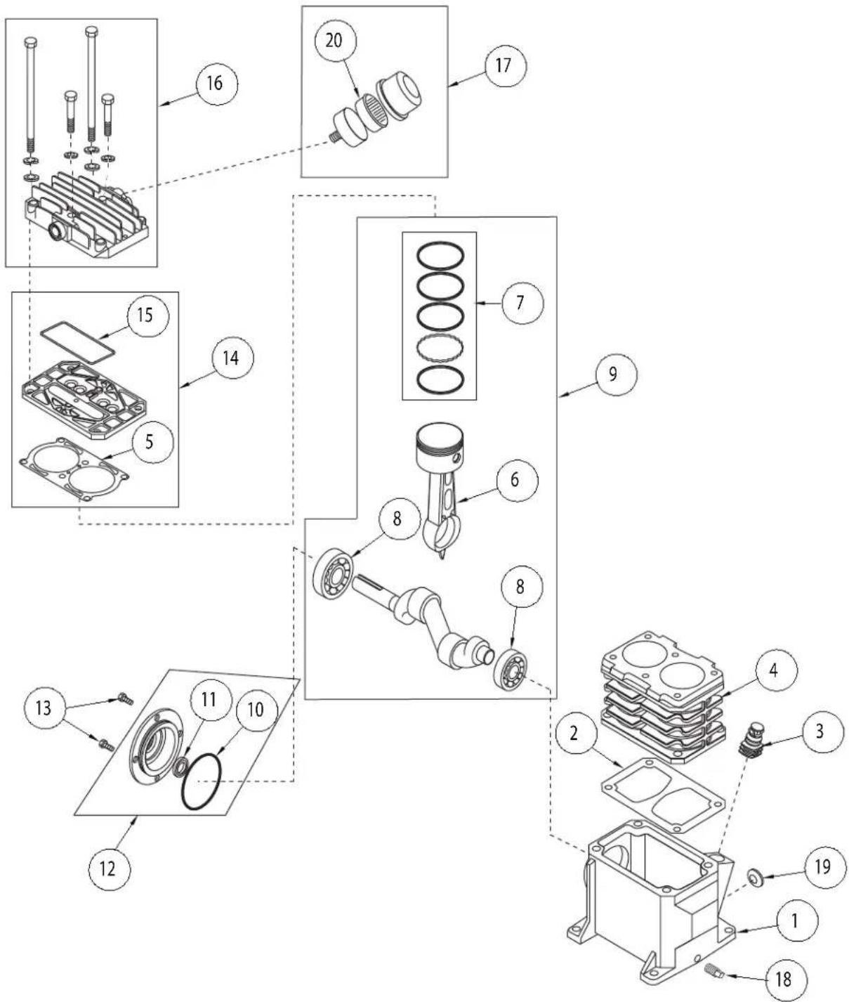
REPAIR PARTS ILLUSTRATION FOR VT4800
text_image
Exploded view diagram of a mechanical assembly with numbered parts for identification and assembly reference.For Repair Parts, visit www.campbellhausfeld.com to find your local distributor 24 hours a day – 365 days a year
Please provide following information:
- Model number
- Serial number (if any)
- Part description and number as shown in parts list
REPAIR PARTS LIST FOR VT4800
| Ref.No. | Description Part Number: Qty. | ||
| 1 | CRANKCASE -- 1 | ||
| 2 | CRANKCASE GASKET | ▲ | 1 |
| 3 | BREATHER VH901100AV 1 | ||
| 4 | CYLINDER | -- 1 | |
| 5 | CYLINDER GASKET | ▲ | 1 |
| 6 | CONNECTING ROD AND PISTON ASSEMBLY | VT020500AV | 2 |
| 7 | PISTON RING SET | -- 2 | |
| 8 | BALL BEARING | -- 2 | |
| 9 | CRANKSHAFT, BEARINGS, RODS, PISTON ASSEMBLY | -- 1 | |
| 10 | O-RING | ▲ | 1 |
| 11 | OIL SEAL | -- 1 | |
| 12 | BEARING CAP ASSEMBLY | VT040200AJ | 1 |
| 13 | M6 X 10 MM SCREW | † | 4 |
| 14 | VALVE PLATE ASSEMBLY | VT491100AV | 1 |
| 15 | VALVE PLATE MOLDED SEAL | ▲ | 1 |
| 16 | CYLINDER HEAD AND FASTENERS | -- 1 | |
| 17 | AIR FILTER ASSEMBLY | VH901700AV 1 | |
| 18 | 1/8 IN.-27 OIL DRAIN PLUG | -- 1 | |
| 19 | SIGHT GLASS | ST191700AV | 1 |
| 20 | AIR FILTER ELEMENT | VH901800AV 1 | |
| REPAIR PARTS KITS | |||
| ▲ | GASKET KIT | VT470900AJ | |
| -- | NOT AVAILABLE | ||
| † | AVAILABLE AT LOCAL HARDWARE STORE | ||
Reminder: Keep your dated proof of purchase for warranty purposes! Attach it to this manual or file it for safekeeping.
LIMITED WARRANTY
- DURATION: From the date of purchase by the original purchaser as follows: One Year.
- WHO GIVES THIS WARRANTY (WARRANTOR): Campbell Hausfeld a Marmon/Berkshire Hathaway Company, 100 Production Drive, Harrison, Ohio, 45030. Visit: www.campbellhausfeld.com
- WHO RECEIVES THIS WARRANTY (PURCHASER): The original purchaser (other than for purposes of resale) of the Campbell Hausfeld compressor.
- WHAT PRODUCTS ARE COVERED BY THIS WARRANTY: Any Campbell Hausfeld air compressor.
- WHAT IS COVERED UNDER THIS WARRANTY: Substantial defects due to material and workmanship with the exceptions noted below.
- WHAT IS NOT COVERED UNDER THIS WARRANTY:
A. Implied warranties, including those of merchantability and FITNESS FOR A PARTICULAR PURPOSE ARE LIMITED FROM THE DATE OF ORIGINAL PURCHASE AS STATED IN THE DURATION. If this compressor is used for commercial, industrial or rental purposes, the warranty will apply for ninety (90) days from the date of purchase. Extreme Duty Contractor Compressors are not limited to a ninety (90) day warranty when used in contractor applications. Four cylinder single-stage and two-stage compressors are not limited to a ninety (90) day warranty when used in commercial or industrial applications. Some States do not allow limitations on how long an implied warranty lasts, so the above limitations may not apply to you.
B. ANY INCIDENTAL, INDIRECT, OR CONSEQUENTIAL LOSS, DAMAGE, OR EXPENSE THAT MAY RESULT FROM ANY DEFECT, FAILURE, OR MALFUNCTION OF THE CAMPBELL HAUSFELD PRODUCT. Some States do not allow the exclusion or limitations of incidental or consequential damages, so the above limitation or exclusion may not apply to you.
C. Any failure that results from an accident, purchaser's abuse, neglect or failure to operate products in accordance with instructions provided in the owner's manual(s) supplied with compressor.
D. Pre-delivery service, i.e. assembly, oil or lubricants, and adjustment.
E. Items or service that are normally required to maintain the product, i.e. lubricants, filters and gaskets, etc.
F. Gasoline engines and components are expressly excluded from coverage under this limited warranty. The Purchaser must comply with the warranty given by the engine manufacturer which is supplied with the product.
G. Additional items not covered under this warranty:
- All Compressors
a. Any component damaged in shipment or any failure caused by installing or operating unit under conditions not in accordance with installation and operation guidelines or damaged by contact with tools or surroundings.
b. Pump or valve failure caused by rain, excessive humidity, corrosive environments or other contaminants.
c. Cosmetic defects that do not interfere with compressor functionality.
d. Rusted tanks, including but not limited to rust due to improper drainage or corrosive environments.
e. Electric motors, check valves and pressure switches after the first year of ownership.
f. Drain cocks.
g. Damage due to incorrect voltage or improper wiring.
h. Other items not listed but considered general wear parts.
i. Pressure switches, air governors and safety valves modified from factory settings.
- Lubricated Compressors
a. Pump wear or valve damage caused by using oil not specified.
b. Pump wear or valve damage caused by any oil contamination or by failure to follow proper oil maintenance guidelines.
- Belt Drive / Direct Drive / Gas Driven Compressors
a. Belts.
b. Ring wear or valve damage from inadequate filter maintenance.
c. Manually adjusted load/unload and throttle control devices.
-
RESPONSIBILITIES OF WARRANTOR UNDER THIS WARRANTY: Repair or replace, at Warrantor's option, compressor or component which is defective, has malfunctioned and/or failed to conform within duration of the warranty period.
-
RESPONSIBILITIES OF PURCHASER UNDER THIS WARRANTY:
A. Provide dated proof of purchase and maintenance records.
B. Portable compressors or components must be delivered or shipped to the nearest Campbell Hausfeld Authorized Service Center. Freight costs, if any, must be borne by the purchaser.
C. Use reasonable care in the operation and maintenance of the products as described in the owner's manual(s).
- WHEN WARRANTOR WILL PERFORM REPAIR OR REPLACEMENT UNDER THIS WARRANTY: Repair or replacement will be scheduled and serviced according to the normal work flow at the servicing location, and depending on the availability of replacement parts.
This Limited Warranty applies in the U.S., Canada and Mexico only and gives you specific legal rights. You may also have other rights which vary from State to State or country to country.
CH CAMPBELL HAUSFELD®
natural_image
Exterior view of a black Campbell Hausfeld air compressor on a four-tire chassis (no visible text or symbols beyond branding)natural_image
Technical line drawing of a vehicle suspension system with two wheels and exhaust plume (no text or symbols)Figure 6
natural_image
Line drawing of a mechanical device with two rotary controls labeled 'OFF' and 'AUTO', no text or symbols present.Figure 7
natural_image
Technical line drawing of a vehicle suspension system with two wheels and exhaust plume (no text or symbols)Figure 8
HUMIDITÉ PRÉSENTE DANS L'AIR COMPRIMÉ
natural_image
Line drawing of a hand holding a small mechanical component (no text or symbols)natural_image
Close-up of a mechanical device with gears and shafts (no visible text or symbols)text_image
Diagram showing mechanical assembly with labeled parts ① and ②, likely illustrating a gear or rack mechanism.Figure 12
Horaire D'entretien
text_image
Technical diagram of an automotive air conditioning system with labeled components and exploded viewstext_image
Exploded view diagram of a mechanical assembly with numbered parts for identification and assembly reference.natural_image
Exterior view of a black Campbell Hausfeld air compressor on a four-tire chassis (no signage or text beyond branding)CH CAMPBELL HAUSFELD.
Harrison, Ohio 45030
ANTES DE COMENZAR
Introducción
natural_image
Technical line drawing of a vehicle chassis with two wheels and a base mount, showing exhaust airflow (no text or symbols)Figura 6
natural_image
Line drawing of a handheld electronic device with a dial and control knob (no text or symbols)Figura 7
natural_image
Technical line drawing of a vehicle suspension system with two wheels and exhaust plume (no text or symbols)Figura 8
natural_image
Line drawing of a hand holding a small mechanical component (no text or symbols)natural_image
Close-up of a mechanical device with gears and shafts (no visible text or symbols)Figura 10 - Filtro de aire
text_image
Diagram showing mechanical assembly with labeled parts ① and ②, likely illustrating a gear or rack mechanism.Figura 12
Almacenamiento
text_image
Technical diagram of a mechanical device with numbered components for identification and assembly reference.Para refacciones, visite www.campbellhausfeld.com para encontrar su distribuidor local.
Ref. No. Description Part Number Qty
| 1 TANQUE, 30 GALONES | AR067500CG 1 | ||
| 2 TUERCA CON ALA,5/16 PULG. -18 | ST146001AV 1 | ||
| 3 RUEDA NEUMÁTICA,10 PULG. | WA006000AV 2 | ||
| 4 PERNO DE ÁRBOL,3/8 PULG.-16 X 3 PULG. | ST084700AV 2 | ||
| 5 TUERCA DE BRIDA,3/8 PULG.-16 | ST033500AV 2 | ||
| 6 MOTOR, 2 HP 120/240 V | MC019800SJ 2 | ||
| 7 BOMBA DE COMPRESOR | VT482200AJ 4 | ||
| 8 TORNILLOAUTORROSCANTE,5/16 PULG. -12 | ST016500AV 1 | ||
| 9 PERNO DE CABEZAHEXAGONAL, 5/16PULG.-18 X 3/4 PULG. | ST016000AV 3 | ||
| 10 | CASQUILLO DE CAUCHO,1/2 PULG. TUBERÍA | ST085200AV 1 | |
| 11 | TUERCA DE COMPRESIÓN,1/2 PULG. | ST033001AV 4 | |
| 12 | POLEA DEL MOTOR | PU015200AV | 4 |
| 13 | BANDA, AX48 | BT020401AV | 6 |
| 14 | TORNILLOAUTORROSCANTE, #5-5/8PULG. | ST073277AV▲ | 2 |
| 15 | CASQUILLO REDUCTOR,1/2 PULG. X 1/4 PULG. NPT | ST071428AV 1 | |
| 16 | CASQUILLO REDUCTOR,1/4 PULG. X 1/8 PULG. NPT | ST071407AV 1 | |
| 17 | NIPLE DE TUBERÍA,1/4 PULG. NPT | ST016800AV 1 | |
| 18 | NIPLE HEXAGONAL DETUBERÍA, 1/4 PULG. NPT | HF002401AV 1 | |
| 19 | VÁLVULA DE SEGURIDADASME, 175 PSI | V-215109AV 1 | |
| 20 | MEDIDOR DE PRESIÓN,300 PSI | GA016306AV | 1 |
| 21 | MANIJA | HL705600AV 2 | |
| 22 | CONECTOR DECOMPRESIÓN | ST159001AV 1 | |
| 23 | TUBO DE ESCAPE, 1/2 PULG. | VT035801AP 1 | |
| 24 | CASQUILLO DE LATÓN, 1/2PULG. TUBERÍA | ST032900AV 1 | |
| 25 | CABLE DE ALIMENTACIÓN,120 V | EC012601AV | 1 |
| 26 | AGARRADERA DEL CABLEDEL INTERRUPTOR DEPRESIÓN | CW209500AV | 1 |
Ref. No. Description Part Number Qty
| 27 | TORNILLO DEL TUBO PASACABLES | ST209800AV 1 | |
| 28 | TORNILLO AUTORROSCANTE DE CABEZA HEXAGONAL, #8 X 3/8 PULG. | ST074407AV 1 | |
| 29 | PERNO DE LA MANIJA, 1/4 PULG.-20 X 1.25 PULG. | PM001901AV | 1 |
| 30 | TUERCA DE LA MANIJA, 1/4 PULG.-20 | PM031101AV | 1 |
| 31 | CABLE DE ALIMENTACIÓN DEL MOTOR | EC012800AV | 1 |
| 32 | VÁLVULA DE DRENAJE, 1/4 PULG. | D-1403 | 1 |
| 33 | SOPORTE DE CAUCHO | ST162602AV 1 | |
| 34 | INTERRUPTOR DE PRESIÓN | CW209000AV | 1 |
| 35 | REGULADOR | RE206202AV | 1 |
| 36 | AGARRADERA | - | 1 |
| 37 | PROTECTOR DE BANDAS, TRASERO | BG313200AV ▲ | 2 |
| 38 | PROTECTOR DE BANDAS, DELANTERO | BG313300AV ▲ | 2 |
| 39 | CLIP DE SUJECIÓN DE PLÁSTICO | ST199700AV ▲ | 1 |
| 40 | SOPORTE DE PROTECTOR DE BANDAS | BG220400AV 1 | |
| 41 | ARANDELA, 5/16 PULG. | ST011200AV ▲ | 4 |
| 42 | CONECTOR QUICK CONNECT, 1/4 PULG. TUBERÍA X 1/8 PULG. NPT | - | 1 |
| 43 | VÁLVULA DE RETENCIÓN | CV221503SJ | 1 |
| 44 | CHAVETA DE MOTOR | KE000900AV 1 | |
| 45 | TORNILLO DE FIJACIÓN, 1/4 PULG.-20 X 1/2 PULG. | ST012200AV 2 | |
| 46 | TORNILLO AUTORROSCANTE, #10-3/8 PULG. | ST073278AV 1 | |
| 47 | TUBO PTFE, 1/4 PULG. X 13 PULG. | ST117802AV 1 | |
| 48 | VOLANTE DE BOMBA | PU015901SJ | 6 |
| 49 | CARCASA DEL FILTRO DE AIRE | VH901700AV | 4 |
| 50 | ELEMENTOS DEL FILTRO DE AIRE | VH901800AV | 1 |
| 51 | RESPIRADERO DEL CÁRTER | VH901100AV | 4 |
| 51 | TORNILLO AUTORROSCANTE | -- | 1 |
Kits de refacciones
| ▲ | KIT DE PROTECTOR DE BANDAS | VT551953AV |
text_image
Exploded view diagram of a mechanical assembly with numbered parts for identification and assembly reference.Para refacciones, visite www.campbellhausfeld.com para encontrar su distribuidor local.


