
DXCM20020US - Compressor DEWALT - Free user manual and instructions
Find the device manual for free DXCM20020US DEWALT in PDF.

| Product type | Electric workshop compressor, two-stage, extremely quiet |
| Brand | DeWalt |
| Model | DXCM20020US |
| Dimensions (L x W x H) | 552 x 469 x 1005 mm |
| Weight | 56.3 kg |
| Tank capacity | 76 liters (20 gallons) |
| Maximum pressure | 200 PSI (1379 kPa) |
| Air flow at 90 PSI | 141.6 L/min (5 SCFM) |
| Motor power | 1.6 HP |
| Power supply | 120 V, 60 Hz, AC, 13.5 A |
| Duty cycle | 5 min on / 5 min off (S3 cycle 50%) |
| Pump type | Oil-free, sealed bearings (lubricated for life) |
| Air outlet fitting | 1/4 inch universal NPT |
| Main features | Quiet operation, thermal protection, safety valve, pressure gauges, pressure regulator |
| Safety | Grounding required, eye and ear protection recommended, safety valve, thermal overload |
| Maintenance | Daily tank drain, weekly air filter check, safety valve inspection before each use |
| Cleaning | Clean exterior with a clean cloth, avoid harsh solvents |
| Spare parts and repairability | Repairs by authorized DeWalt service center, identical replacement parts required |
| Warranty | 1 year limited (material and workmanship defects) |
| General information | Use for pneumatic tools < 5 SCFM, inflation, cleaning. Do not use for breathing. |
Frequently Asked Questions - DXCM20020US DEWALT
User questions about DXCM20020US DEWALT
0 question about this device. Answer the ones you know or ask your own.
Ask a new question about this device
Download the instructions for your Compressor in PDF format for free! Find your manual DXCM20020US - DEWALT and take your electronic device back in hand. On this page are published all the documents necessary for the use of your device. DXCM20020US by DEWALT.
USER MANUAL DXCM20020US DEWALT
Extremely Quiet 2-Stage, 200 PSI max, 20 gallon (76 l) Electric Workshop Compressor
Definitions: Safety Alert Symbols and Words
This instruction manual uses the following safety alert symbols and words to alert you to hazardous situations and your risk of personal injury or property damage.

NOTICE: Indicates a practice not related to personal injury which, if not avoided, may result in property damage.
Fig. A
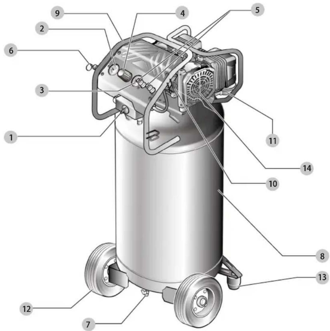
1 On/off switch
2 Air tank pressure gauge
3 Regulated pressure gauge
4 Pressure regulator knob
5 Quick couplers
6 Safety valve
7 Air tank drain valve
8 Air tank
9 Handle
10 Power cord wrap
11 Air intake filter
12 Wheel
13 Rubber foot
14 Electric motor & air compressor pump
WARNING! Read all safety warnings and all instructions. Failure to follow the warnings and instructions may result in electric shock, fire and/or serious injury.

WARNING: To reduce the risk of injury, read the instruction manual.
Safety symbol
Some of the following symbols may be used on this compressor. Please study them and learn their meaning. Proper interpretation of these symbols will allow you to operate the compressor better and safer.
Symbol Name Designation / Explanation
| V Volts Voltage. | ||
| A Amperes Current. | ||
| Hz Hertz Frequency (cycles per second). | ||
| ~ | Alternating Current Type of current. | |
| Class II Construction Double-insulated construction. | ||
 | Wet Conditions Alert Do not expose to rain or use in damp locations. | |
 | Read the Operator's Manual | To reduce the risk of injury, user must read and understand operator's manual before using this product. |
 | Eye Protection | Always wear safety goggles, safety glasses with side shields, or a full face shield when operating this product. |
 | Safety Alert Precautions that involve your safety. | |
 | Risk of Bursting | Do not adjust the regulator to result in output pressure greater than the marked maximum pressure of the attachment. Do not use at a pressure greater than the rated maximum pressure of this compressor. |
 | Risk of Fire of Explosion | Do not spray flammable liquid in a confined area. Spray area must be well ventilated. Do not smoke while spraying or spray where spark or flame is present. Keep compressors as far from the spraying area as possible, at least 15 feet from the spraying area and all explosive vapors. |
 | Risk of Electrical Shock | Hazardous Voltage: disconnect from power source before servicing. Compressor must be grounded. |
 | Hot Surface | To reduce the risk of injury or damage, avoid contact with any hot surface. |
 | Risk to Hearing | Always wear ear protection when using this compressor. Failure to do so may result in hearing loss. |
 | Risk to Breathing | Air obtained directly from the air compressor should never be used to supply air for human consumption. |
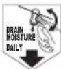 | Drain Moisture Daily Drain out the tank daily. | |
Intended Use
Your compressor is designed for use in a variety of air system applications. Always match hoses, connectors, air tools, and accessories to the capabilities of the air compressor.
IMPORTANT SAFETY INSTRUCTIONS
SAVE ALL WARNINGS AND INSTRUCTIONS FOR FUTURE REFERENCE

GER: RISK OF EXPLOSION OR FIRE

What can happen How to prevent it
| It is normal for electrical contacts within the motor and pressure switch to spark. | Always operate the compressor in a well ventilated area free of combustible materials, gasoline, or solvent vapors. |
| If electrical sparks from compressor come into contact with flammable vapors, they may ignite, causing fire or explosion. | If spraying flammable materials, locate compressor at least 20 feet (6.1 m) away from spray area. An additional length of hose may be required. |
| Store flammable materials in a secure location away from compressor. | |
| Restricting any of the compressor ventilation openings will cause serious overheating and could cause fire. | Never place objects against or on top of compressor pump. |
| Operate compressor in an open area at least 12" (30.5 cm) away from any wall or obstruction that would restrict the flow of fresh air to the ventilation openings. | |
| Operate compressor in a clean, dry well ventilated area. Do not operate unit indoors or in any confined area. | |
| Unattended operation of this product could result in personal injury or property damage. To reduce the risk of fire, do not allow the compressor to operate unattended. | Always remain in attendance with the product when it is operating. |
| Always turn off and unplug unit when not in use. |

ION: RISK FROM NOISE

What can happen How to prevent it
| Under some conditions and duration of use, noise from this product may contribute to hearing loss. | Always wear certified safety equipment: ANSI S12.6 (S3.19) hearing protection. |
What can happen How to prevent it
| The compressed air directly from your compressor is not safe for breathing. The air stream may contain carbon monoxide, toxic vapors, or solid particles from the air tank. Breathing these contaminant's can cause serious injury or death. | Air obtained directly from the compressor should never be used to supply air for human consumption. In order to use air produced by this compressor for breathing, suitable filters and in-line safety equipment must be properly installed. In-line filters and safety equipment used in conjunction with the compressor must be capable of treating air to all applicable local and federal codes prior to human consumption. |
| Exposure to chemicals in dust created by power sanding, sawing, grinding, drilling, and other construction activities may be harmful. | Work in an area with good cross ventilation. Read and follow the safety instructions provided on the label or safety data sheets for the materials you are spraying. Always use certified safety equipment: OSHA/MSHA/NIOSH respiratory protection designed for use with your specific application. |
| Sprayed materials such as paint, paint solvents, paint remover, insecticides, weed killers, may contain harmful vapors and poisons. |

ING: RISK OF BURSTING

Air Tank: On February 26, 2002, the U.S. Consumer Product Safety Commission published Release # 02-108 concerning air compressor tank safety:
Air compressor receiver tanks do not have an infinite life. Tank life is dependent upon several factors, some of which include operating conditions, ambient conditions, proper installations, field modifications, and the level of maintenance. The exact effect of these factors on air receiver life is difficult to predict.
If proper maintenance procedures are not followed, internal corrosion to the inner wall of the air receiver tank can cause the air tank to unexpectedly rupture allowing pressurized air to suddenly and forcefully escape, posing risk of injury to consumers.
Your compressor air tank must be removed from service by the end of the year shown on your tank warning label. The following conditions could lead to a weakening of the air tank, and result in a violent air tank explosion::
What can happen How to prevent it
| Failure to properly drain condensed water from air tank, causing rust and thinning of the steel air tank. | Drain air tank daily or after each use. If air tank develops a leak, replace it immediately with a new air tank or replace the entire compressor. |
| Modifications or attempted repairs to the air tank. | Never drill into, weld, or make any modifications to the air tank or its attachments. Never attempt to repair a damaged or leaking air tank. Replace with a new air tank. |
English
| Unauthorized modifications to the safety valve or any other components which control air tank pressure. | The air tank is designed to withstand specific operating pressures. Never make adjustments or parts substitutions to alter the factory set operating pressures. |
Attachments & accessories:
| Exceeding the pressure rating of air tools, spray guns, air operated accessories, tires, and other inflatables can cause them to explode or fly apart, and could result in serious injury. | Follow the equipment manufacturers recommendation and never exceed the maximum allowable pressure rating of attachments. Never use compressor to inflate small low pressure objects such as children's toys, footballs, basketballs, etc. |
Tires:
| Over inflation of tires could result in serious injury and property damage. | Use a tire pressure gauge to check the tires pressure before each use and while inflating tires; see the tire sidewall for the correct tire pressure.NOTE: Air tanks, compressors and similar equipment used to inflate tires can fill small tires similar to these very rapidly. Adjust pressure regulator on air supply to no more than the rating of the tire pressure. Add air in small increments and frequently use the tire gauge to prevent over inflation. |

NING: RISK OF ELECTRICAL SHOCK

What can happen How to prevent it
| Your air compressor is powered by electricity. Like any other electrically powered device, If it is not used properly it may cause electric shock. | Never operate the compressor outdoors when it is raining or in wel conditions. |
| Never operate compressor with protective covers removed or damaged. | |
| Repairs attempted by unqualified personnel can result in serious injury or death by electrocution. | Any electrical wiring or repairs required on this product should be performed by a DeWALT factory service center or a DeWALT authorized service center in accordance with national and local electrical codes. |
| Electrical Grounding:Failure to provide adequate grounding to this product could result in serious injury or death from electrocution. SeeGrounding Instructionsunder Electrical Safety. | Make certain that the electrical circuit to which the compressor is connected provides proper electrical grounding, correct voltage and adequate fuse protection. |

NING: RISK FROM FLYING OBJECTS

What can happen How to prevent it
| The compressed air stream can cause soft tissue damage to exposed skin and can propel dirt, chips, loose particles, and small objects at high speed, resulting in property damage or personal injury. | Always wear certified safety equipment: ANSI Z87.1 eye protection (CAN/CSA Z94.3) with side shields when using the compressor. |
| Never point any nozzle or sprayer toward any part of the body or at other people or animals. | |
| Always turn the compressor off and bleed pressure from the air hose and air tank before attempting maintenance, attaching tools or accessories. |

NING: RISK OF HOT SURFACES

What can happen How to prevent it
| Touching exposed metal such as the compressor head, engine head, engine exhaust or outlet tubes, can result in serious burns. | Never touch any exposed metal parts on compressor during or immediately after operation. Compressor will remain hot for several minutes after operation. Do not reach around protective shrouds or attempt maintenance until unit has been allowed to cool. |

NING: RISK OF INJURY FROM LIFTING

What can happen How to prevent it
| Serious injury can result from attempting to lift too heavy an object. | The compressor is too heavy to be lifted by one person. Obtain assistance from others before lifting. |

NING: RISK FROM MOVING PARTS

What can happen How to prevent it
| Moving parts such as the pulley, flywheel, and belt can cause serious injury if they come into contact with you or your clothing. | Never operate the compressor with guards or covers which are damaged or removed |
| Keep your hair, clothing, and gloves away from moving parts. Loose clothes, jewelry, or long hair can be caught in moving parts. | |
| Air vents may cover moving parts and should be avoided as well. | |
| Attempting to operate compressor with damaged or missing parts or attempting to repair compressor with protective shrouds removed can expose you to moving parts and can result in serious injury. | Any repairs required on this product should be performed by a DeWALT factory service center or a DeWALT authorized service center. |
What can happen How to prevent it
| Unsafe op er a tion of your air compressor could lead to se ri ous in ju ry or death to you or others. | Review and understand all instructions and warnings in this manual. |
| Becomefamiliarwiththeoperation and con trols of the air compressor. | |
| Keep operating area clear of all persons, pets, and obstacles. | |
| Keep chil dren away from the air compressor at all times. | |
| Do not operate the product when fatigued or under the influence of alcohol or drugs. Stay alert at all times. | |
| Never defeat the safety fea tures of this product. | |
| Equip area of operation with a fire extinguisher. | |
| Do not op er ate machine with missing, broken, or unauthorized parts. | |
| Never stand on the compressor. |

NING: RISK OF FALLING

What can happen How to prevent it
| A portable compressor can fall from a table, workbench, or roof causing damage to the compressor and could result in serious injury or death to the operator. | Always operate compressor in a stable secure position to prevent accidental movement of the unit. Never operate compressor on a roof or other elevated position. Use additional air hose to reach high locations. |
SAVE THESE INSTRUCTIONS FOR FUTURE USE
WARNING: Some dust created by power sanding,
saving, grinding, drilling, and other construction activities contains chemicals known to the State of California to cause cancer, birth defects or other reproductive harm. Some examples of these chemicals are:
- lead from lead-based paints,
• crystalline silica from bricks and cement and other masonry products, and
• arsenic and chromium from chemically-treated lumber.
Your risk from these exposures varies, depending on how often you do this type of work. To reduce your exposure to these chemicals: work in a well ventilated area, and work with approved safety equipment, such as those dust masks that are specially designed to filter out microscopic particles.
- Avoid prolonged contact with dust from power sanding, sawing, grinding, drilling, and other
construction activities. Wear protective clothing and wash exposed areas with soap and water. Allowing dust to get into your mouth, eyes, or lay on the skin may promote absorption of harmful chemicals.
WARNING: Use of this tool can generate and/or adverse dust, which may cause serious and permanent respiratory or other injury. Always use NIOSH/OSHA approved respiratory protection appropriate for the dust exposure. Direct particles away from face and body.
English
GENERAL SAFETY RULES
WARNING: Read and understand all instructions. Suppose to follow all instructions listed below may result in electric shock, fire, and/or serious personal injury.
WARNING: To avoid serious personal injury, do not attempt to use this product until you read thoroughly and understand completely the operator's manual. Save this operator's manual and review frequently for continuing safe operation and instructing others who may use this product.
SAVE THESE INSTRUCTIONS
Work area
- Keep your work area clean and well lit. Cluttered benches and dark areas invite accidents. The floor must not be slippery from wax or dust.
- Do not operate compressor in explosive atmospheres, such as in the presence of flammable liquids, gases, or dust. Compressors create sparks which may ignite the dust or fumes.
- Keep bystanders, children, and visitors away while operating compressor and tools. Distractions can cause you to lose control.
- Operate the air compressor in an open area at least 18 in. away from any wall or object that could restrict the flow of fresh air to ventilation openings.
Electrical safety
- Avoid body contact with grounded surfaces such as pipes, radiators, ranges, and refrigerators. There is an increased risk of electric shock if your body is grounded.
- Don't expose compressor to rain or wet conditions. Water entering a compressor will increase the risk of electric shock.
- Do not abuse the cord. Never use the cord to carry the compressor or pull the plug from an outlet. Keep the cord away from heat, oil, sharp edges, or moving parts. Replace damaged cords immediately. Damaged cords increase the risk of electric shock.
- When operating a compressor outside, use an outdoor extension cord marked "W-A" or "W".
These cords are rated for outdoor use and reduce the risk of electric shock.
Personal safety
- Eye protection which conforms to ANSI specifications and provides protection against flying particles both from the FRONT and SIDE should ALWAYS be worn by the operator and
others in the work area when loading, operating, or servicing this compressor. Eye protection is required to guard against flying fasteners and debris, which could cause severe eye injury.
- The employer and/or user must ensure that proper eye protection is worn. We recommend a Wide Vision Safety Mask for use over eyeglasses or standard safety glasses that provide protection against flying particles both from the front and side. Always use eye protection which is marked to comply with ANSI Z87.1.
- Additional safety protection will be required in some environments. For example, the working area may include exposure to a noise level which can lead to hearing damage. The employer and user must ensure that any necessary hearing protection is provided and used by the operator and others in the work area. Some environments will require the use of head protection equipment. When required, the employer and user must ensure that head protection marked to comply with ANSI Z89.1 is used.
- Stay alert, watch what you are doing, and use common sense when operating a compressor. Do not use compressor and tools while tired or under the influence of drugs, alcohol, or medication. A moment of inattention while operating compressors may result in serious personal injury.
- Dress properly. Do not wear loose clothing or jewelry. Contain long hair. Keep your hair, clothing, and gloves away from moving parts. Loose clothes, jewelry, or long hair can be caught in moving parts.
- Do not overreach. Keep proper footing and balance at all times. Proper footing and balance enables better control of the tool in unexpected situations.
- Use safety equipment. Always wear eye protection. A dust mask, nonskid safety shoes, hard hat, or hearing protection must be used for appropriate conditions.
Do not use on a ladder or unstable support. Stable footing on a solid surface enables better control of the tool in unexpected situations.
Compressor use and care
- Do not exceed the pressure rating of any component in the system.
- Protect material lines and air lines from damage or puncture. Keep the hose and power cord away from sharp objects, chemical spills, oil, solvents, and wet floors.
- Check hoses for weak or worn condition before each use, making certain all connections are secure. Do not use if a defect is found. Purchase a new hose or notify an authorized service center for examination or repair.
- Release the pressure within the system slowly. Dust and debris may be harmful.
- Store idle tools out of the reach of children and other untrained persons. Tools are dangerous in the hands of untrained users.
- Maintain tools with care. Follow maintenance instructions. Properly maintained tools are easier to control.
- Check for misalignment or binding of moving parts, breakage of parts, and any other condition that may affect the compressor's operation. If damaged, have the compressor serviced before using. Many accidents are caused by poorly maintained compressors.
- Never point any tool toward yourself or others.
- Keep the exterior of the air compressor dry, clean, and free from oil and grease. Always use a clean cloth when cleaning. Never use brake fluids, gasoline, petroleum-based products, or any strong solvents to clean the unit. Following this rule will reduce the risk of deterioration of the enclosure plastic.
Service
- Compressor service must be performed only by qualified repair personnel. Service or maintenance performed by unqualified personnel may result in a risk of injury.
- Disconnect the power supply, open the drain valve to decompress the tank and allow water to drain, and allow the air compressor to become cool to the touch before servicing. Turn the pressure regulator knob fully counterclockwise after shutting off the compressor.
- When servicing a compressor, use only identical replacement parts. Follow the instructions in the Maintenance section of this manual. Use of unauthorized parts or failure to follow the Maintenance instructions may create a risk of injury.
DANGER: This compressor/pump is not equipped should not be used to supply breathing quality air. Additional equipment would be necessary to properly filter and purify the air to meet minimal specifications for Grade D breathing as described in Compressed Gas Association Commodity Specification G 7.1 - 1996, OSHA 29 CFR 1910.134.
Compressed Gas Association, 14501 George Carter Way, Suite 103, Chantilly VA 20151-1788, (703) 788-2700,
www.cganet.com. Any such additional equipment has not been examined and no implication of proper use for breathing air is intended or implied.
If this compressor is altered in any way, existing warranties shall be voided. Seller disclaims any liabilities whatsoever for any loss, personal injury, or damage.
SPECIFIC SAFETY RULES
- Know your compressor. Read the operator's manual carefully. Learn its applications and limitations, as well as the specific potential hazards related to this compressor. Following this rule will reduce the risk of electric shock, fire, or serious injury.
- Drain the tank of moisture after each day's use. If the unit will not be used for a while, it is best to leave the drain valve open until such time as it is to be used. This will allow moisture to completely drain out and help prevent corrosion on the inside of tank.
- Risk of Fire or Explosion. Do not spray flammable liquid in a confined area. The spray area must be well ventilated. Do not smoke while spraying or spray where sparks or a flame is present. Keep compressors as far from the spraying area as possible, at least 15 feet from the spraying area and all explosive vapors.
- Risk of Bursting. Do not adjust the regulator to result in output pressure greater than the marked maximum pressure of the attachment. Do not use at a pressure greater than the rated maximum pressure of this compressor.
- If connected to a circuit protected by fuses, use time-delay fuses with this product.
-
To reduce the risk of electric shock, do not expose to rain. Store indoors.
-
Inspect the tank yearly for rust, pin holes, or other imperfections that could cause it to become unsafe. Never weld or drill holes in the air tank.
- Make sure the hose is free of obstructions or snags. Entangled or snarled hoses can cause loss of balance or footing and may become damaged.
- Use the air compressor only for its intended use. Do not alter or modify the unit from the original design or function.
- Always be aware that misuse and improper handling of this compressor can cause injury to yourself and others.
- Never leave a compressor unattended with the air hose attached.
- Do not operate this compressor if it does not contain a legible warning label.
- Do not continue to use a tool or hose that leaks air or does not function properly.
- Always disconnect the air supply and power supply before making adjustments, servicing a compressor, or when a compressor is not in use.
- Do not attempt to pull or carry the air compressor by the hose.
- Your tool may require more air consumption than this air compressor is capable of providing.
- When a combustible liquid is sprayed there can be danger of fire or explosion, especially in a closed area. Read instruction manual before operating.
- Arcing parts. Use spray gun hose at least 25 feet long and keep the compressor/motor at least 20 feet away from explosive vapors.
English
- Always follow all safety rules recommended by the manufacturer of your tool, in addition to all safety rules for the air compressor. Following these rules will reduce the risk of serious personal injury.
- Never direct a jet of compressed air toward people or animals. Take care not to blow dust and dirt towards yourself or others. Following this rule will reduce the risk of serious injury.
- Protect your lungs. Wear a face or dust mask if the operation is dusty. Following this rule will reduce the risk of serious personal injury.
- Do not use this air compressorto spray chemicals. Your lungs can be damaged by inhaling toxic fumes. A respirator may be necessary in dusty environments or when spraying paint. Do not carry while painting.
- Inspect compressor cords and hoses periodically and, if damaged, have repaired at your nearest Authorized Service Center. Constantly stay aware of cord location. Following this rule will reduce the risk of electric shock or fire.
- Never use an electrical adaptor with this grounded plug.
- Check damaged parts. Before further use of the air compressor or air tool, a guard or other part that is damaged should be carefully checked to determine that it will operate properly and perform its intended function. Check for alignment of moving parts, binding of moving parts, breakage of parts, mounting, and any other conditions that may affect its operation. A guard or other part that is damaged should be properly repaired or replaced by an authorized service center. Following this rule will reduce the risk of shock, fire or serious injury.
- Make sure your extension cord is in good condition. When using an extension cord, be sure to use one heavy enough to carry the current your product will draw. A wire gauge size (A.W.G.) of at least 14 is recommended for an extension cord 50 feet or less in length. A cord exceeding 100 feet is not recommended. If in doubt, use the next heavier gauge. The smaller the gauge number, the heavier the cord. An undersized cord will cause a drop in line voltage resulting in loss of power and overheating.
- Risk of injury from lifting. Serious injury can result from attempting to lift too heavy an object. The compressor is too heavy to be lifted by one person. Obtain assistance from others before lifting.
- Risk of serious injury or property damage when transporting compressor. Oil can leak or spill and could result in fire or breathing hazard; serious injury or death can result. Oil leaks will damage carpet, paint or other surfaces in vehicles or trailers. Always place compressor on a protective mat when transporting to protect against damage to vehicle from leaks. Remove compressor from vehicle immediately upon arrival at your destination.
WARNING: This product can expose you to chemicals including lead, which is known to the state of California to cause cancer and birth defects or other reproductive harm. For more information go to www.p65warnings.ca.gov
- Save these instructions. Refer to them frequently and use them to instruct others who may use this air compressor. If you loan someone this compressor, loan them these instructions also.
WARNING: The operation of any compressor can result in foreign objects being thrown into your eyes, which can result in severe eye damage. Before beginning compressor operation, always wear safety goggles, safety glasses with side shields, or a full face shield when needed. We recommend Wide Vision Safety Mask for use over eyeglasses or standard safety glasses with side shields. Always use eye protection which is marked to comply with ANSI Z87.1.
ELECTRICAL SAFETY
Extension Cords
Using extension cords is not recommended. The use of extension cords will cause voltage to drop resulting in power loss to the motor and overheating.
Instead of using an extension cord, increase the working reach of the air hose by attaching another length of hose to its end. Attach additional lengths of hose as needed.
If an extension cord must be used, be sure to follow these guidelines:
- Use only 3-wire extension cords that have 3-prong grounding plugs and 3-pole receptacles that accept the air compressor's plug.
-
When using the air compressor at a considerable distance from the power source, use an extension cord heavy enough to carry the current that the compressor will draw. An undersized extension cord will cause a drop in line voltage, resulting in a loss of power and causing the motor to overheat. Use the chart provided below to determine the minimum wire size required in an extension cord.
-
Only round jacketed cords listed by Underwriter's Laboratories (UL) should be used.
**Ampere rating (on air compressor data plate)
0-2.0 2.1-3.4 3.5-5.0 5.1-7.0 7.1-12.0 12.1-16.0
| Cord Length | Wire Size (A.W.G.) |
| 25' 14 14 14 14 14 14 | |
| 50' 14 14 14 14 14 12 | |
| 100' 14 14 14 12 10 – |
** Used on 12 gauge - 20 amp circuit.
Note: A.W.G. = American Wire Gauge
- When working with the air compressor outdoors, use an extension cord that is designed for outside use. This is indicated by the letters "W-A" on the cord's jacket.
- Before using an extension cord, inspect it for loose or exposed wires and cut or worn insulation.
WARNING: Keep the extension cord clear of the working area. Position the cord so that it will not get caught on lumber, tools, or other obstructions while you are working with a compressor. Failure to do so can result in serious personal injury.
WARNING: Check the extension cords before each damaged, replace immediately. Never use the air compressor with a damaged cord since touching the damaged area could cause electrical shock resulting in serious personal injury.
NOTE: Use longer air hoses instead of long extension cords. Your air compressor will run better and last longer.
Electrical Connection
- This air compressor is powered by a precision built electric motor. It should be connected to a power
supply that is 120 volts, 60 Hz, AC only (normal household current).
- Do not operate this compressor on direct current (DC). A substantial voltage drop will cause a loss of power and the motor will overheat. If the air compressor does not operate when plugged into an outlet, double check the power supply.
Speed and Wiring
- The no-load speed of the electric motor varies by model and specification. The motor speed is not constant and decreases under a load or with lower voltage. For voltage, the wiring in a shop is as important as the motor's horsepower rating.
- A line intended only for lights cannot properly carry a compressor motor. Wire that is heavy enough for a short distance will be too light for a greater distance. A line that can support one compressor may not be able to support two or three compressors.
Grounding Instructions
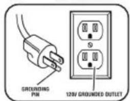
WARNING: Risk of electrical shock. In the event of a short circuit, grounding reduces the risk of shock by providing an escape wire for the electric current. This air compressor must be properly grounded.
The portable air compressor is equipped with a cord having a grounding wire with an appropriate grounding plug.
- The cord set and plug 16 with this unit contains a grounding pin 17. This plug MUST be used with a grounded outlet 18.
Fig. B
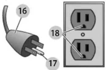
IMPORTANT: The outlet being used must be installed and grounded in accordance with all local codes and ordinances.
- Ensure the outlet being used has the same configuration as the grounded plug. DO NOT USE AN ADAPTER.
- Inspect the plug and cord before each use. Do not use if there are signs of damage.
- If these grounding instructions are not completely understood, or if in doubt as to whether the compressor is properly grounded, have the installation checked by a qualified electrician.
DANGER: Risk of electrical shock. IMPROPER COUNDED CAN RESULT IN ELECTRICAL SHOCK.
- Do not modify the plug provided. If it does not fit the available outlet, a correct outlet should be installed by a qualified electrician.
• Repairs to the cord set or plug MUST be made by a qualified electrician.
SPECIFICATIONS
| Model DXCM20020US |
| Weight 124 lbs (56.3 kg) |
| Height 39.6" (1005.0 mm) |
| Width 18.5" (469.0 mm) |
| Length 21.7" (552.0 mm) |
| Air Tank Capacity (Gallons) 20 (76 liters) |
| Air Pressure 200 PSI max. (1379 kPa) |
| Air delivery @ 90 PSI (620.5 kPa) 5 |
| Running Horsepower 1.6 HP |
| Input 120 V, 60 Hz, AC only, 13.5 Amps. |
| Duty Cycle 5 Minutes ON /5 Minutes OFF |
FEATURES
Know your Air Compressor
See Figure 2.
Before attempting to use this product, familiarize yourself with all operating features and safety rules.
Oil-free Universal Motor
Your air compressor features permanently lubricated bearings.
Manual On/Off Power Switch
This switch is used to start or stop the air compressor. Moving the switch to the (ON) position will provide automatic power to the pressure switch which will allow the motor to start when the air tank pressure is below the factory set cut-in pressure. When in the (ON) position, the pressure switch stops the motor when the air tank pressure reaches the factory set cut-out pressure. Moving the switch to the (OFF) position will remove power from the motor and stop the air compressor.
Air intake filter
This filter is designed to clean air coming into the pump. To ensure the pump continually receives a clean, cool, dry air supply this filter must always be clean and ventilation opening free from obstructions.
Electric Motor & Air Compressor Pump
The motor is used to power the pump. The electric motor has a thermal overload protector. If the motor overheats for any reason, the thermal overload will cut off power, thus preventing the motor from being damaged. Wait until the motor is cool.
Air compressor pump: to compress air, the piston moves up and down in the cylinder. On the down stroke, air is drawn in through the air intake valve while the exhaust valve remains closed. On the upstroke, air is compressed, the intake valve
closes and compressed air is forced out through the exhaust valve, into the discharge line, through the check valve and into the air tank.
Safety Valve
This valve is designed to prevent system failures by relieving pressure from the system when the compressed air reaches a predetermined level. The valve is preset by the manufacturer and must not be modified in any way.
Air Tank Drain Valve
The drain valve is used to remove moisture from the air tank.
Air Tank Pressure Gauge
The tank pressure gauge indicates the pressure of the air in the tank.
Regulated Pressure Gauge
The current line pressure is displayed on the regulator pressure gauge. This pressure can be adjusted by rotating the pressure regulator knob.
Pressure Regulator Knob
Use the pressure regulator knob to adjust the amount of air being delivered through the hose.
The air pressure coming from the air tank is controlled by the regulator knob. Turn the pressure regulation knob clockwise to increase discharge pressure, and counterclockwise to decrease discharge pressure. Follow tool operating instructions for recommended pressure range.
Air Tank
The tank is used to store the compressed air.
Quick Coupler
The outlet is used to connect the 1/4 in. NPT air hose.
Overload Protector (not shown)
This air compressor is equipped with a thermal overload device which will turn the air compressor off automatically, if the air compressor becomes overheated. If the motor turns OFF repeatedly, check for the following possible causes first: Low Voltage from the outlet. Lack of proper ventilation or outside air or room temperature too high. Extension cord too long or wrong gauge wire used.
To reset the air compressor:
- Turn the air compressor off.
- Unplug the air compressor and allow it to cool for 30 minutes.
- Plug the air compressor into an approved outlet.
- Turn the air compressor on.
ASSEMBLY
Unpacking
This product has been shipped completely assembled, except the wheels and the rubber feet.
- Carefully remove the unit and any accessories from the box.
- Inspect the compressor and tools carefully to make sure no breakage or damage occurred during shipping.
- Do not discard the packing material until you have carefully inspected and satisfactorily operated the compressor.
Packing List
-Air Compressor (1)
-Operator's Manual (1)
WARNING: If any parts are missing do not operate the compressor until the missing parts are replaced. Failure to do so could result in possible serious personal injury.
WARNING: Do not attempt to modify a compressor or create accessories not recommended for use with this compressor. Any such alteration or modification is misuse and could result in a hazardous condition leading to possible serious personal injury.
CAUTION: Do not lift compressor from rear haw.
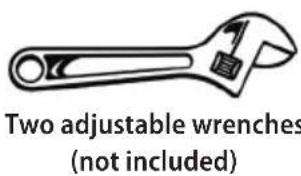
Tools needed
- The following tools are needed to tighten the screws to the nuts of wheels and rubber feet.
Fig. C
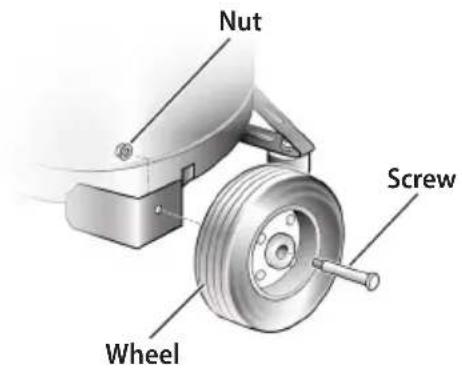
Assembling the wheels
- Mount the wheels as shown in figure D.
● Tighten firmly with an adjustable wrench (not included) to secure the wheels in position.
Fig. D
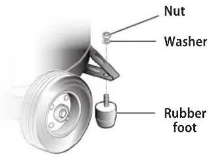
Assembling the rubber feet
- Mount the rubber feet as shown in figure E.
- Tighten firmly with an adjustable wrench (not included) to secure the rubber foot in position.
Fig. E
Attaching Hose
- The quick coupling supplied with the unit is universal type and accepts the three most popular styles of quick connect plugs: Industrial, Automotive and ARO. One hand push-to-connect operation makes connections simple and easy. The two quick connect bodies allow the use of two tools at the same time.
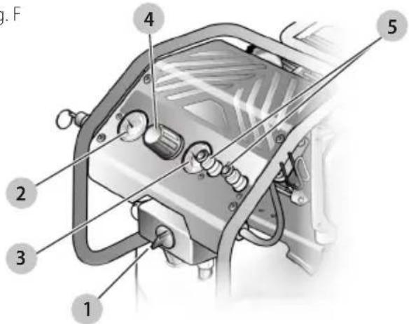
- Insert the hose into the quick coupler ⑤ already installed on the compressor (Fig. F).
WARNING: Do not attach any tools to the open door of the hose until breaking in of the pump has been completed.
- Firmly grasp the open end of the hose; hold facing away from yourself and others.
Fig. F
ENGLISH
Breaking in the Pump
- Check and tighten all fittings.
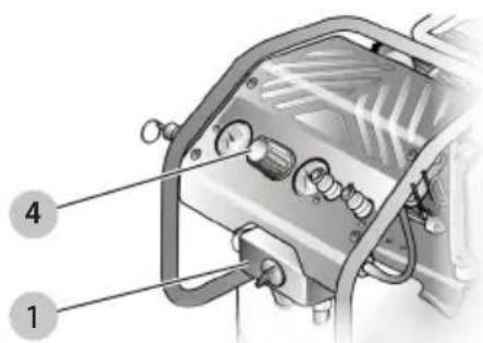
- Turn the pressure regulator knob ④ (Fig. F) fully clockwise to open the air flow.
- Place the switch ① in the OFF (O) position (Fig. G) and plug in the power cord.
Fig. G
![OFF [O] / AUTO [I] OFF [O] / AUTO [I]](/content/2026/05/749820/images/f4f60660f5933c6881761658e7b0907177c9512f9cfc0225dabb9c71636bd1ce.jpg)
- Open the drain valve completely.
Fig. H
- Turn the air compressor ON (I) and run the air compressor for 10 minutes to break in pump parts.
- Place the switch ① in the OFF (O) position.
- Close the drain valve.
LIFT AND TRANSPORT
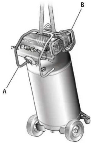
Lift
- To lift the compressor, use the front handle only (A) or both handles (A and B).
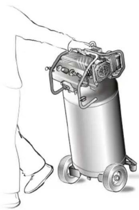
- We suggest you use a couple of straps wrapped around the two handles as shown in fig. 1.
WARNING: Do not attempt to lift the compressor by yourself.
WARNING: Do not use the rear handle B alone for lifting.
WARNING: Do not lift the unit by the pipes.
WARNING: Do not touch the pipes as they are very hot.
Transport
- You can use the front handle for pulling the unit (see Fig. J).
CAUTION: DO NOT try to pull the unit by the rear table.
- When transporting the compressor, do not drop the unit or allow the unit to fall from its vertical position.
Fig. J
natural_image
Illustration of a person pushing a cylindrical industrial machine with wheels (no text or symbols visible)OPERATION
Applications
Air compressors are utilized in a variety of air system applications. Match hoses, connectors, air tools, and accessories to the capabilities of the air compressor.
You may use this compressor for purposes listed below:
- Operating air powered compressor and tools requiring less than 5 SCFM @ 90 PSI.
- Powering pneumatic nail guns, inflating tires, cleaning / blowing with pressurized air.
WARNING: Do not allow familiarity with compressor and tools to make you careless. Remember that a careless fraction of a second is sufficient to inflict serious injury.
WARNING: Always wear safety goggles or safety glasses with side shields when operating compressor. Failure to do so could result in objects being thrown into your eyes resulting in possible serious injury.
CAUTION: Do not use in an environment that is dusty or otherwise contaminated. Using the air compressor in this type of environment may cause damage to the unit.
Using the Air Compressor
WARNING: Always ensure the switch is in the (O) position and the regulator pressure gauge reads zero before changing air tools or disconnecting the hose from the air outlet. Failure to do so could result in possible serious personal injury.
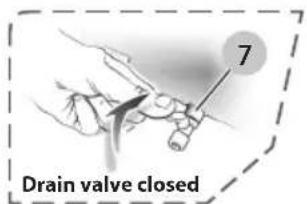
- Ensure the tank drain valve ⑦ is closed (see Fig. K).
- Ensure the ON/OFF switch ① is in the OFF (O) position and the air compressor is unplugged (see Fig. K).
- Ensure the pressure regulator knob ④ is turned fully counterclockwise (see Fig. K).
- If not already installed, attach the hose to the compressor.
Fig. K
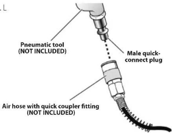
- Connect the air powered tools to the air hose by inserting the male quick-connect plug to the quick-coupler at the
end of the hose (see Fig. L).
Fig. L
- Connect the power cord to the power supply.
- Turn the ON/OFF switch ① to the ON (I) position.
- Rotate the pressure regulator knob ④ to the desired line pressure. Turning the knob clockwise increases air pressure at the outlet; turning the knob counterclockwise reduces air pressure at the outlet.
NOTE: Before connecting or disconnecting air tools, turn the regulator knob counterclockwise to stop the flow of air. - Following all safety precautions in this manual and the manufacturer's instructions in the air tool manual, you may now use your air-powered tool.
- If using an inflation accessory with a quick-connect fitting, control the amount of air flow with the pressure regulator knob. Turning the knob fully counterclockwise will completely stop the flow of air.
NOTE: Always use the minimum amount of pressure necessary for your application. Using a higher pressure than needed will drain air from the tank more rapidly and cause the unit to cycle on more frequently. - When finished, always drain the tank and unplug the unit. Never leave the unit plugged in and/or running unattended.
WARNING: Check the air tool manual to ensure correct air pressure regulator setting for optimum operation of your air tools. If you are using an air tool not originally included in the package contents list (not necessarily supplied with the air compressor model you have purchased), your tool may require more air consumption than this air compressor is designed to supply. Always read your air tool owner's manual to match the correct air supply to your air tool to avoid damage to the tool or risk of personal injury.
Duty cycle:
To avoid overheating of the electric motor, this compressor is designed for intermittent operation as indicated on the dataplate: 5 minutes ON / 5 minutes OFF. This indication is equivalent to a S3 50% duty cycle: if the compressor run time exceeds 5 minutes in any 10 minute period, then the application requires more air than the compressor is capable to deliver.
ENGLISH
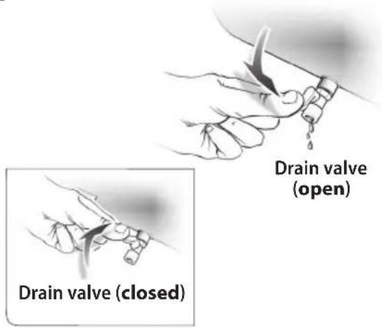
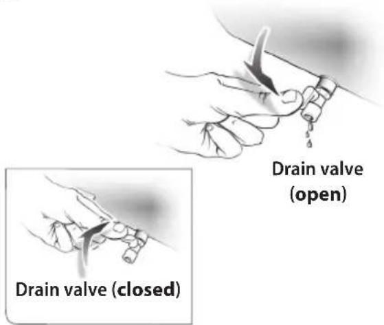
Draining the Tank
To help prevent tank corrosion and keep moisture out of the air used, the tank of the compressor should be drained daily.
To drain:
- Verify that the compressor is turned off.
- Holding the handle, tilt the compressor toward the drain valve so that it's set in a lower position.
- Open the drain valve by rotating it 14 turn counterclockwise.
- Keep the compressor tilted until all moisture has been removed.
- Drain moisture from tank into a suitable container.
NOTE: Condensate is a polluting material and should be disposed of in compliance with local regulations.
- If drain valve is clogged, release all air pressure by pulling the safety valve. Remove and clean valve, then reinstall.
Fig. M
WARNING: Unplug the air compressor and release all air from the tank before servicing. Failure to depressurize tank before attempting to remove valve may cause serious personal injury.
- Close the drain valve by rotating it 14 turn clockwise.
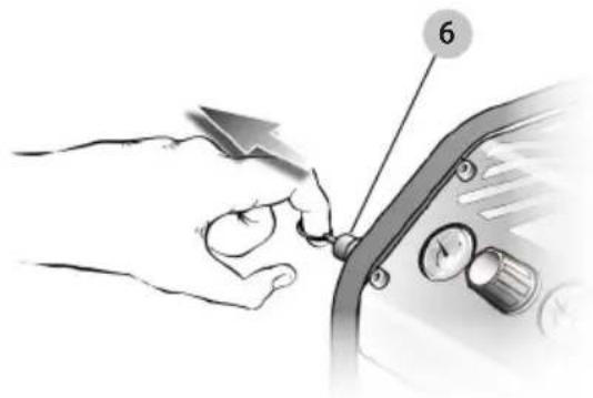
Checking the Safety Valve
DANGER: Do not attempt to tamper with safety Anything loosened from this device could fly up and hit you. Failure to heed this warning could result in death or serious personal injury.
The safety valve will automatically release air if the air receiver pressure exceeds the preset maximum. The valve should be checked before each day of use by pulling the ring by hand.
- Turn the air compressor on and allow the tank to fill. The compressor will shut off when the pressure reaches the preset maximum.
- Turn the air compressor off.
- Pull the ring on the safety valve ⑥ to release air for three to five seconds.
- Release the ring. Air must immediately stop escaping when the ring is released. Any continued loss of air after releasing the safety valve ring indicates a problem with the safety
valve. Discontinue use and seek service before continued use of the air compressor.
Fig. N
natural_image
Illustration of a hand turning a knob on a car intake manifold with a dial (no text or symbols)WARNING: If air leaks after the ring has been reused, or if the valve is stuck and cannot be actuated by the ring, do not use the air compressor until the safety valve has been replaced. Use of the air compressor in this condition could result in serious personal injury.
End of Operation/Storage
- Turn the ON/OFF switch to the OFF (O) position.
- Unplug power cord from wall outlet and wrap around handle area to prevent damage when not in use.
- Wearing safety glasses, drain tank of air by pulling the ring on the safety valve. Use other hand to deflect fast moving air from being directed toward your face.
- Drain tank of condensation by opening drain valve on bottom of tank. Tank pressure should be below 10 PSI when draining tank.
● Air hose should be disconnected from compressor and hung open ends down to allow any moisture to drain. - Compressor and hose should be stored in a cool, dry place.
MAINTENANCE
WARNING: When servicing, use only identical replacement parts. Use of any other parts may create a hazard or cause product damage.
WARNING: Always wear safety goggles or safety glasses with side shields during compressor operation or when blowing dust. If operation is dusty, also wear a dust mask.
WARNING: Always release all pressure, disconnect from power supply, and allow unit to cool to the touch before cleaning or making repairs on the air compressor.
General Maintenance
Humidity in the air causes condensation to form in the air tank. This condensation should be drained daily and/or every hour, using the instructions found in Draining the Tank. The safety valve automatically releases air if the air receiver pressure exceeds the preset maximum. Check the safety valve before each use following the instructions found in
Checking the Safety Valve.
Inspect the tank yearly for rust, pin holes, or other imperfections that could cause it to become unsafe.
Avoid using solvents when cleaning plastic parts. Most plastics are susceptible to damage from various types of commercial solvents and may be damaged by their use. Use clean cloths to remove dirt, dust, oil, grease, etc.
WARNING: Do not at any time let brake fuel, gasoline, petroleum-based products, penetrating oils, etc., come in contact with plastic parts. Chemicals can damage, weaken or destroy plastic which may result in serious personal injury.
Lubrication
All the bearings in this compressor are lubricated with a sufficient amount of high grade lubricant for the life of the unit under normal operating conditions. Therefore, no further lubrication of the bearings is required.
NOTE: Any service operations not included in this section should be performed by a DeWALT factory service center or a DrWALT authorized service center.
MAINTENANCE CHART
| Procedure Before each use | Daily or after each use | Weekly See tank warning label |
| Check safety valve X | ||
| Inspect air filter ^1X | ||
| Drain air tank | X | |
| Check for unusual noise/vibration | X | |
| Check for air leaks ^2 | X | |
| Clean compressor exterior | X | |
| Remove tank from service | X ^3 | |
| ^1 Perform more frequent in dusty or humid conditions. | ||
| ^2 To check for air leaks apply a solution of soapy water around joints. While compressor is pumping to pressure and after pressure cuts out, look for air bubbles to form. | ||
| ^3 For more information, call 1-833-913-1299 | ||
TROUBLESHOOTING
| Problem Possible Cause Possible Solution | ||
| The compressor does not run. Loss of power or overheating.There is no electrical power being supplied to compressor or the power switch is in the OFF position.A fuse has blown at the power supply.A breaker has tripped at the power supply.Thermal overload open.The pressure switch is bad.Tank is full of air. | Check for proper use of extension cord.Check to be sure the compressor is plugged in and the power switch is in the ON position.Replace the fuse at the power supply.Reset the breaker at the power supply and determine why the problem happened.First unplug the compressor and wait until it becomes cool. Motor will restart when cool.Replace the pressure switch.Compressor will turn on when tank pressure drops to cut-in pressure. | |
| The motor hums, but does not run or runs slowly. | The voltage from the power supply is low.The gauge wire or the length of extension cord is wrong.The motor winding is shorted or broken.The unloader or check valve is defective. | Check the voltage with a voltmeter.Use the correct wire gauge and length extension cord.Take the compressor to a service center.Take the compressor to a service center. |
| The fuses blow or the circuit breaker trips repeatedly. | The fuse size is incorrect or the circuit is overloaded.The gauge wire or the length of extension cord is wrong.The unloader or check valve is defective. | Check the fuse or breaker at the power supply is the correct size and type. Be sure to use only time-delay fuses to avoid overloading a circuit, disconnect other electrical appliances from circuit or operate compressor on its own branch circuit.Use the correct wire gauge and length extension cord.Take the compressor to a service center. |
| The thermal overload protector cuts out repeatedly. | The voltage from the power supply is low.A poorly ventilated room is causing the motor to overheat.The gauge wire or the length of extension cord is wrong. | Check the voltage with a voltmeter.Move the compressor to well-ventilated area.Check for proper gauge wire and cord length. |
| The air receiver pressure drops when the compressor shuts off. | The connections are loose or leaking (fittings, tubing, etc.).The drain valve is loose.The check valve is leaking. | Check all the connections with soapy water and look for bubbles. Tighten any loose connections until the leak stops.Tighten the drain valve.Take the compressor to a service center. |
| There is excessive moisture in the air discharge. | There is excessive water in the air tank.The humidity is high. | Drain the tank to remove water.Move the compressor to an area of less humidity or use an air line filter to reduce moisture discharge in the tank. |
| Air is leaking from the compressor. The hose connection is loose or improperly sealed.The air hose is broken or damaged. | Ensure connections are sealed with thread sealing tape and tightened.Replace the air hose. | |
| The compressor runs continuously. The tank drain valve is open.The pressure switch is defective.The usage is excessive. | Ensure the tank drain valve is closed.Take the compressor to a service center.Decrease the amount of tool run-time; the compressor is not large enough to supply the air requirement of the tool. | |
| The compressor vibrates. The compressor mounting bolts are loose. Tighten mounting bolts. | ||
| The air output is lower than normal. The inlet valves are broken.The connections are leaking. | Take the compressor to a service center.Apply thread sealing tape to fitting and tighten. | |
REPAIRS
WARNING: To assure product SAFETY and RECEPTIBILITY, repairs, maintenance and adjustment (including brush inspection and replacement, when applicable) should be performed by a DEWALT factory service center or a DEWALT authorized service center. Always use identical replacement parts.
Register Online
Thank you for your purchase. Register your product now for:
- WARRANTY SERVICE: Registering your product will help you obtain more efficient warranty service in case there is a problem with your product.
- CONFIRMATION OF OWNERSHIP: In case of an insurance loss, such as fire, flood or theft, your registration of ownership will serve as your proof of purchase.
- FOR YOUR SAFETY: Registering your product will allow us to contact you in the unlikely event a safety notification is required under the Federal Consumer Safety Act.
Register online at www.dewalt.com/register.
Limited 1 Year Warranty
DrWALT will repair, without charge, any defects due to faulty materials or workmanship for one year from the date of purchase. This warranty does not cover part failure due to normal wear or tool abuse. For further detail of warranty coverage and warranty repair information, visit www.dewalt.com or call 1-833-913-1299. This warranty does not apply to accessories or damage caused where repairs have been made or attempted by others. This warranty gives you specific legal rights and you may have other rights which vary in certain states or provinces.
FREE WARNING LABEL REPLACEMENT: If your warning labels become illegible or are missing, call 1-833-913-1299 for a free replacement.
English
GLOSSARY
Air Filter: Porous element contained within a metal or plastic housing attached to the compressor cylinder head which removes impurity from the intake air of the compressor.
Air Tank: Cylindrical component which contains the compressed air.
Check Valve: Device that prevents compressed air from flowing back from the air tank to the compressor pump.
Cut-In Pressure: The low pressure at which the motor will automatically restart.
Cut-Off Pressure: The high pressure at which the motor will automatically shut off.
Electric Motor: Device which provides the rotational force necessary to operate the compressor pump.
Manual On/Off Switch: Control which turns the air compressor on or off. The pressure switch will not automatically start and control the compressor unless the manual on/off switch is in the ON (1) position.
NPT (National Pipe Thread): National Pipe Thread is a U.S. standard for tapered (NPT) or straight (NPS) threads used to join pipes and fittings. A thread sealing tape must be used to provide a leak-free seal on pipe threaded connections.
Pressure Regulator Knob: Regulates the outgoing pressure from the air outlet to the tool. It is possible to increase or decrease the pressure at the outlet by adjusting this control knob.
Pressure Switch: Automatically controls the on/off cycling of the compressor. It stops the compressor when the cut-off pressure in the tank is reached and starts the compressor when the air pressure drops below the cut-in pressure.
PSI (Pounds Per Square Inch): Measurement of the pressure exerted by the force of the air. The actual psi is measured by a pressure gauge on the compressor.
Pump: Produces the compressed air with a reciprocating piston contained within the cylinder.
Regulator Pressure Gauge (Outlet pressure): Displays the current line pressure. Line pressure is adjusted by rotating the pressure regulator knob.
Safety Valve: Prevents air pressure in the air tank from rising over a predetermined limit.
SCFM (Standard Cubic Feet Per Minute): A unit of measure of air delivery.
L/min (Liter Per Minute): A unit of measure of air delivery.
Tank Pressure Gauge: Indicates the pressure in the air tank.
Thermal Overload Switch: Automatically shuts off the compressor if the temperature of the electric motor exceeds a predetermined limit.
natural_image
Illustration of a person pushing a cylindrical industrial machine with wheels (no text or symbols visible)UTILISATION
Applications
natural_image
Illustration of a hand turning a knob on a vehicle's side panel with a dial (no text or symbols)ESPAÑOL
natural_image
Illustration of a person pushing a cylindrical industrial machine with wheels (no text or symbols visible)FUNCIONAMIENTO
Usos
natural_image
Illustration of a hand turning a car's keyway with a knob and dial (no text or symbols)| 10.0 | 10.0 | |
| 10.0 | 10.0 | |
| 10.0 | 10.0 | |
| 10.0 | 10.0 | |
| 10.0 | 10.0 | |
| 10.0 | 10.0 | |
| 10.0 | 10.0 | |
| 10.0 | 10.0 | |
| 10.0 | 12.5 | |
| 10.0 | 12.5 | |
| 10.0 | 12.5 | |
| 10.0 | 12.5 | |
| 10.0 | 12.5 | |
| 10.0 | 12.5 | |
| 10.0 | 12.5 | |
| 10.0 | 12.5 | |
| 10.0, 12.5, 13.5, 14.5, 15.5, 16.5, 17.5, 18.5, 19.5, 20.5, 21.5, 22.5, 23.5, 24.5, 25.5, 26.5, 27.5, 28.5, 29.5, 30.5, 31.5, 32.5, 33.5, 34.5, 35.5, 36.5, 37.5, 38.5, 39.5, 40.5, 41.5, 42.5, 43.5, 44.5, 45.5, 46.5, 47.5, 48.5, 49.5, 50.5, 51.5, 52.5, 53.5, 54.5, 55.5, 56.5, 57.5, 58.5, 59.5, 60.5, 61.5, 62.5, 63.5, 64.5, 65.5, 66.5, 67.5, 68.5, 69.5, 70.5, 71.5, 72.5, 73.5, 74.5, 75.5, 76.5, 77.5, 78.5, 79.5, 80.5, 81.5, 82.5, 83.5, 84.5, 85.5, 86.5, 87.5, 88.5, 89.5, 90.5, 91.5, 92.5, 93.5, 94.5, 95.5, 96.5, 97.5, 98.5, 99.5, 100 |
The Ground Truth image displays a single, continuous horizontal line, which is a stylistic or background element (like a rule line on paper). According to Rule 2, such lines must be ignored by the OCR result. The provided OCR content is "____", which consists of underscores. Underscores are not equivalent to a solid line and are not permitted under the “Stylistic/Background Lines (Ignore)” rule. Outputting underscores for a stylistic line violates the rule and constitutes an error. Therefore, the OCR result is inconsistent with the Ground Truth.
[Non-Text]
[Non-Text]
[Non-Text]
The Ground Truth image displays a single, solid horizontal line, which is a stylistic or background element (like a rule line on paper). According to Rule 2, such lines must be ignored by the OCR result. The provided OCR content is "____", which consists of underscores. Underscores are not equivalent to a solid line and are not permitted under the “Stylistic/Background Lines (Ignore)” rule. Outputting underscores for a solid line violates the rule and constitutes an error. Therefore, the OCR result is inconsistent with the Ground Truth.
[Non-Text]
The Ground Truth image displays a single, solid horizontal line, which is a stylistic or background element (like a rule line on paper). According to Rule 2, such lines must be ignored by the OCR result. The OCR content provided is "", which consists of no characters. Since the OCR output correctly ignores the stylistic line, it complies with Rule 2. Therefore, the OCR result is consistent with the Ground Truth.
[Non-Text]
The Ground Truth image displays a single, solid horizontal line, which is a stylistic or background element (like a rule line on paper), not a placeholder for text. According to Rule 2, such stylistic/background lines must be ignored by the OCR result. The OCR content provided is four underscores (`____`), which incorrectly interprets the line as a fill-in-the-blank placeholder. This is a formatting error because the OCR output should not contain any text symbols for stylistic lines. Therefore, the OCR result is inconsistent with the Ground Truth.
[Non-Text]
[Non-Text]
The Ground Truth image displays a single, solid horizontal line. According to Rule 2 (UNDERSCORE & LINE RULES), this is a stylistic or background line, not a placeholder underscore. Therefore, the OCR result must ignore it and output nothing or only meaningful text. The provided OCR content is "____", which consists of four underscores. This is an incorrect interpretation of the line as a placeholder, violating the rule that stylistic lines must be ignored. The OCR has hallucinated placeholder underscores where none should exist in the GT. This adheres to the strict requirement to ignore such lines.
The Ground Truth image displays a single, solid horizontal line. According to Rule 2 (UNDERSCORE & LINE RULES), this is a stylistic or background line, not a placeholder underscore. Therefore, the OCR result must ignore it. The provided OCR content is "____", which consists of four underscores. This is an incorrect interpretation of the line as a placeholder, violating the rule that stylistic lines must be ignored. The OCR has hallucinated text (underscores) where none should exist based on the GT's visual context. Hence, the OCR result is inconsistent with the Ground Truth.
[Non-Text]
The Ground Truth image displays a single, solid horizontal line, which is a stylistic or background element (like a rule line on paper). According to Rule 2, such lines must be ignored by the OCR result. The OCR content provided is "", which consists of no characters. Since the OCR output correctly ignores the stylistic line, it complies with Rule 2. Therefore, the OCR result is consistent with the Ground Truth.
[Non-Text]
The Ground Truth image displays a single, continuous horizontal line, which is a stylistic or background element (like a rule line on paper). According to Rule 2, such lines must be ignored by the OCR result. The provided OCR content is "____", which consists of underscores. Underscores are not equivalent to a solid line and are not permitted under the “Stylistic/Background Lines (Ignore)” rule. Outputting underscores for a stylistic line violates the rule and constitutes an error. Therefore, the OCR result is inconsistent with the Ground Truth.
The Ground Truth image displays a single, continuous horizontal line, which is a stylistic or background element (like a rule line on paper). According to Rule 2, such lines must be ignored by the OCR result. The OCR content provided is "", which consists of no characters. Since the OCR output correctly ignores the stylistic line, this complies with Rule 2. Therefore, the OCR result is consistent with the Ground Truth.
[Non-Text]
[Non-Text]
[Non-Text]
(1) AD = BD = 1
[Non-Text]
[Non-Text]
The Ground Truth image displays a single, solid horizontal line, which is a stylistic or background element (like a rule line on paper). According to Rule 2, such lines must be ignored by the OCR result. The provided OCR content is "____", which consists of underscores. Underscores are not equivalent to a solid line and are not permitted under the “Stylistic/Background Lines (Ignore)” rule. Outputting underscores for a solid line violates the rule and constitutes an error. Therefore, the OCR result is inconsistent with the Ground Truth.
[Non-Text]
The Ground Truth image displays a single, solid horizontal line, which is a stylistic or background element (like a rule line on paper). According to Rule 2, such lines must be ignored by the OCR result. The OCR content provided is "", which consists of no characters. Since the OCR output correctly ignores the stylistic line, it complies with Rule 2. Therefore, the OCR result is consistent with the Ground Truth.
[Non-Text]
The Ground Truth image displays a single, solid horizontal line, which is a stylistic or background element (like a rule line on paper), not a placeholder for text. According to Rule 2, such stylistic/background lines must be ignored by the OCR result. The OCR content provided is four underscores (`____`), which incorrectly interprets the line as a fill-in-the-blank placeholder. This is a formatting error because the OCR output should not contain any text symbols for stylistic lines. Therefore, the OCR result is inconsistent with the Ground Truth.
[Non-Text]
[Non-Text]
The Ground Truth image displays a single, solid horizontal line. According to Rule 2 (UNDERSCORE & LINE RULES), this is a stylistic or background line, not a placeholder underscore. Therefore, the OCR result must ignore it and output nothing or only meaningful text. The provided OCR content is "____", which consists of four underscores. This is an incorrect interpretation of the line as a placeholder, violating the rule that stylistic lines must be ignored. The OCR has hallucinated placeholder underscores where none should exist in the GT. This adheres to the strict requirement to ignore such lines.
The Ground Truth image displays a single, solid horizontal line. According to Rule 2 (UNDERSCORE & LINE RULES), this is a stylistic or background line, not a placeholder underscore. Therefore, the OCR result must ignore it and output nothing or only meaningful text. The provided OCR content is "____", which consists of four underscores. This is an incorrect interpretation of the line as a placeholder, violating the rule that stylistic lines must be ignored. The OCR has hallucinated placeholder underscores where none exist in the GT. Hence, the OCR result is inconsistent with the Ground Truth.
[Non-Text]
The Ground Truth image displays a single, solid horizontal line, which is a stylistic or background element (like a rule line on paper). According to Rule 2, such lines must be ignored by the OCR result. The OCR content provided is "", which consists of no characters. Since the OCR output correctly ignores the stylistic line, it complies with Rule 2. Therefore, the OCR result is consistent with the Ground Truth.
[Non-Text]
The Ground Truth image displays a single, solid horizontal line, which is a stylistic or background element (like a rule line on paper). According to Rule 2, such lines must be ignored by the OCR result. The OCR content provided is "", which consists of no characters. Since the OCR output correctly ignores the stylistic line, it complies with Rule 2. Therefore, the OCR result is consistent with the Ground Truth.
DEWALT® and the DEWALT logo are registered trade marks of Stanley Black & Decker, Inc. or an affiliate thereof and are used under license.
Manufactured by: FNA S.p.A. - Via Einaudi 6, Robassomero (TO) Italy.
The following are trademarks for one or more DeWALT power tools: the yellow and black color scheme, the "D" shaped air intake grill, the array of pyramids on the handgrip, the kit box configuration, and the array of lozenge-shaped humps on the surface of the tool.

- Definitions: Safety Alert Symbols and Words
- Safety symbol
- Intended Use
- IMPORTANT SAFETY INSTRUCTIONS
- SAVE ALL WARNINGS AND INSTRUCTIONS FOR FUTURE REFERENCE
- NING: RISK OF FALLING
- SAVE THESE INSTRUCTIONS FOR FUTURE USE
- English
- GENERAL SAFETY RULES
- SAVE THESE INSTRUCTIONS
- Work area
- Electrical safety
- Personal safety
- Compressor use and care
- Service
- SPECIFIC SAFETY RULES
- Extension Cords
- Electrical Connection
- Speed and Wiring
- Grounding Instructions
- FEATURES
- Know your Air Compressor
- Oil-free Universal Motor
- Manual On/Off Power Switch
- Air intake filter
- Electric Motor & Air Compressor Pump
- Safety Valve
- Air Tank Drain Valve
- Air Tank Pressure Gauge
- Regulated Pressure Gauge
- Pressure Regulator Knob
- Air Tank
- Quick Coupler
- Overload Protector (not shown)
- To reset the air compressor:
- ASSEMBLY
- Unpacking
- Packing List
- Tools needed
- Assembling the wheels
- Assembling the rubber feet
- Attaching Hose
- Breaking in the Pump
- LIFT AND TRANSPORT
- Lift
- Transport
- OPERATION
- Applications
- Using the Air Compressor
- Duty cycle:
- Draining the Tank
- To drain:
- Checking the Safety Valve
- End of Operation/Storage
- MAINTENANCE
- General Maintenance
- Checking the Safety Valve.
- Lubrication
- REPAIRS
- Register Online
- Limited 1 Year Warranty
- GLOSSARY
- UTILISATION
- ESPAÑOL
- FUNCIONAMIENTO
- Usos
Brand : DEWALT
Model : DXCM20020US
Category : Compressor