H-11632 - Fan Uline - Free user manual and instructions
Find the device manual for free H-11632 Uline in PDF.

User questions about H-11632 Uline
0 question about this device. Answer the ones you know or ask your own.
Ask a new question about this device
Download the instructions for your Fan in PDF format for free! Find your manual H-11632 - Uline and take your electronic device back in hand. On this page are published all the documents necessary for the use of your device. H-11632 by Uline.
USER MANUAL H-11632 Uline
TOOLS NEEDED
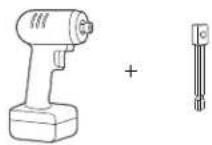
Impact Wrench with Socket Adapter (optional)

8 mm Socket (optional)

10 mm Socket (optional)
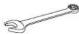
8 mm Wrench
10 mm Wrench
14 mm Wrench
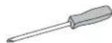
Phillips Screwdriver
natural_image
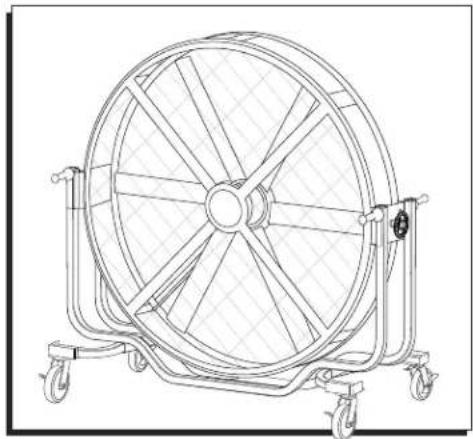
Technical line drawing of a large industrial fan with multiple blades mounted on wheels (no text or symbols)TECHNICAL DATA
| Size 72" | |
| Voltage 120V | |
| Frequency 60Hz | |
| Amps 6A | |
| Wattage | 450W |
| Maximum Speed | 300 RPM |
| Net Weight | 397 lbs. |
| Gross Weight | 584 lbs. |
SAFETY

CAUTION! Read and save these instructions. Read carefully before attempting to assemble, install, operate or maintain this product. Do not use the fan if any part is damaged or missing. Automatic reset safety device in motor. To reduce risk of injury, disconnect power supply before servicing. Protect yourself and others by observing all safety information. Failure to comply with instructions could result in personal injury and/or property damage. Retain instructions for future reference.

WARNING! To reduce the risk of fire or electric shock, do not use this fan with any solid-state speed control device. This fan has a grounded plug. To reduce the risk of fire or electric shock, this plug is intended to fit in an outlet only one way. If the plug does not fit into the outlet, contact a qualified electrician. Do not attempt to bypass this safety feature. To reduce the risk of fire, electric shock or injury to persons, do not use replacement parts that have not been recommended by the manufacturer.

NOTE: To comply with UL507, fan should not be used in unattended areas.
- Ensure that the power source conforms to the electrical requirements of the fan.
- Where a two-prong wall receptacle is encountered, it must be replaced with a properly grounded three-prong receptacle installed in accordance with the United States National Electrical Code (NEC) and all applicable local codes and ordinances. This work must be done by a qualified electrician, using copper wire only.
- Where possible, avoid the use of extension cords. If they must be used, minimize the risk of overheating by ensuring that they are UL Listed and of the proper gauge and length. Never use a single extension cord to operate more than one fan.
- Do not kink the cord or allow it to contact oil, grease, chemicals, hot surfaces, or sharp or abrasive objects.
SAFETY CONTINUED
- Operate fan only with its OSHA-compliant guards in place to prevent persons and/or objects from contacting the revolving fan blades. Any other use voids warranty and may create unsafe conditions.
- Fan is intended for general air circulation only. It must not be used in potentially dangerous locations such as flammable, explosive, chemical-laden or wet atmospheres. Do not attach ductwork to the fan.
-
Fan motor is equipped with an automatically resetting control circuit that will disconnect power if the motor experiences overcurrent. Always unplug fan before removing guard, as motor may start unexpectedly.
-
Do not operate any fan with a damaged cord or plug. Discard fan or contact Uline Customer Service at 1-800-295-5510.
- Do not run cord under carpeting. Do not cover cord with throw rugs, runners or similar coverings. Do not route cord under furniture or appliances. Arrange cord away from traffic area and where it will not be tripped over.
- Disconnect the fan when moving it from one location to another.
- Ensure the fan is on a stable, flat surface while it is in operation.
- Disconnect fan when removing guards for cleaning.
- Do not use outdoors.
FEATURES
text_image
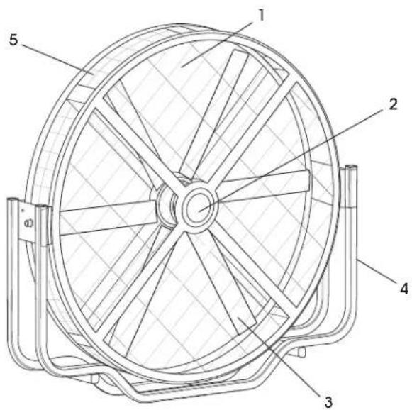
Technical diagram of a fan with numbered components labeled 1 through 5
text_image
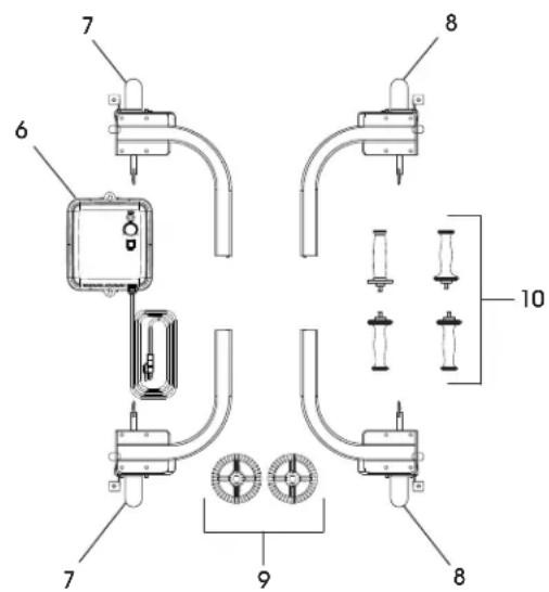
Technical diagram of a mechanical or electrical component assembly with numbered parts and labeled parts 6, 7, 8, 9, and 10.| # DESCRIPTION QTY. | |
| 1 Grill 8 | |
| 2 Logo Cover 1 | |
| 3 Fan Blade 6 | |
| 4 Frame Tubing | 1 |
| 5 Side Grill | 1 |
| # | DESCRIPTION QTY. | |
| 6 | Control Box | 1 |
| 7 | Caster Assembly – Left Side | 2 |
| 8 | Caster Assembly – Right Side | 2 |
| 9 | Tilt Knob | 2 |
| 10 | Handle | 4 |
UNPACKING
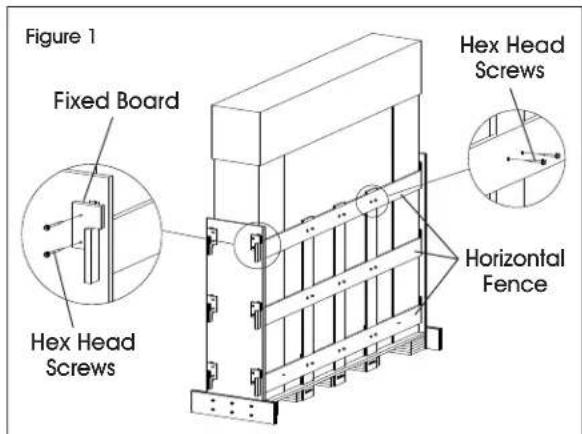
- Remove hex head screws from the horizontal fence and the fixed board on the left and right side using an 8 mm wrench. Take off all the fixed boards. (See Figure 1)
text_image
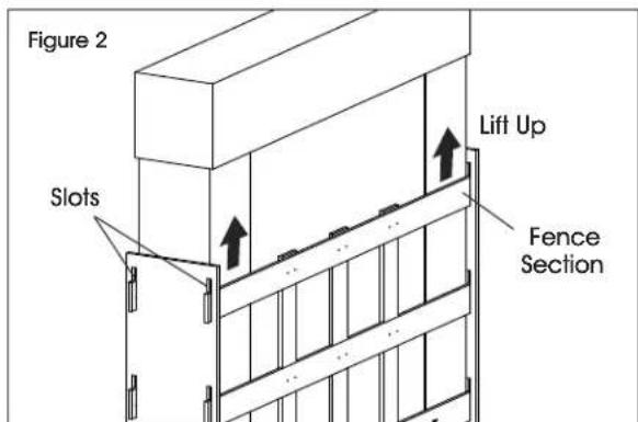
Figure 1 Fixed Board Hex Head Screws Horizontal Fence- Lift the top horizontal fence section up and pull it out slowly through slots in side boards. Repeat for remaining five fences. (See Figures 2-3)
text_image
Figure 2 Slots Lift Up Fence Section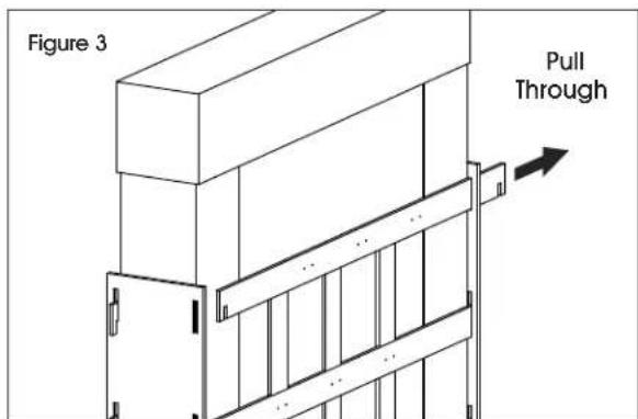
text_image
Figure 3 Pull Through- Remove the top carton cover, then remove the carton surrounding the fan. (See Figures 4-5)
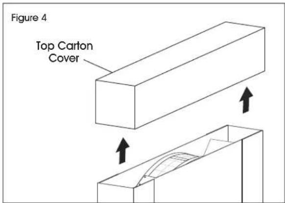
text_image
Figure 4 Top Carton Cover
natural_image
Technical line drawing of a mechanical device with internal components and external supports (no text or symbols)- Take off the accessory box from the fan head carefully. It contains control box, tilt knobs and handles. (See Figure 6)
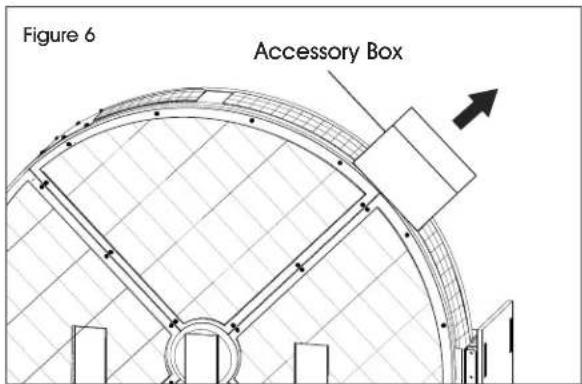
text_image
Figure 6 Accessory BoxUNPACKING CONTINUED
- Remove the hex head screws fixed to side boards using a 10 mm wrench and pull out the side boards. (See Figure 7)
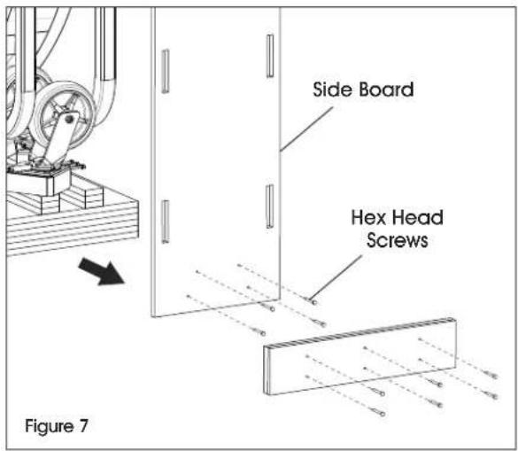
text_image
Side Board Hex Head Screws Figure 7- Take out the caster assembly from the frame tubing of the fan. (See Figure 8)
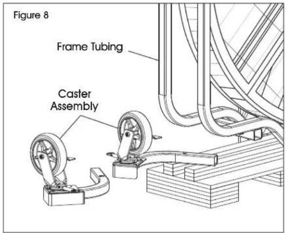
text_image
Figure 8 Frame Tubing Caster AssemblyASSEMBLY
CASTER ASSEMBLY INSTALLATION
- Loosen the hex head screws from the base of the frame tubing using a 14 mm wrench. (See Figure 9)
- Push down on snap buttons and insert caster assembly into the base of the frame tubing. Snap buttons will lock into place once fully inserted. (See Figure 9)
- Re-tighten the hex head screws located in frame tubing.
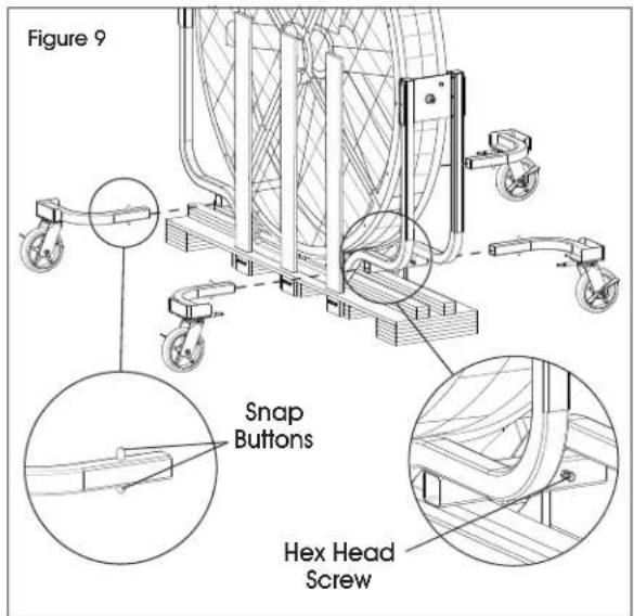
text_image
Figure 9 Snap Buttons Hex Head Screw
CAUTION! The caster assembly includes a brake and direction lock. When finished with the installation, lock the brakes before powering on the fan. (See Figure 10)
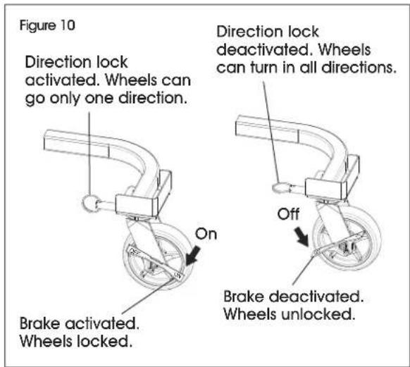
text_image
Figure 10 Direction lock activated. Wheels can go only one direction. On Brake activated. Wheels locked. Direction lock deactivated. Wheels can turn in all directions. Off Brake deactivated. Wheels unlocked.ASSEMBLY CONTINUED
REMOVE THE REMAINING FENCE

NOTE: To reduce risk of injury, finish the caster assembly installation before removing remaining fence pieces.
Remove the hex head screws from the bottom of fencing using a 10 mm wrench and pull out the remaining fence pieces. (See Figure 11)
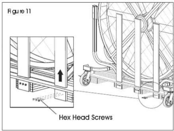
text_image
Figure 11 Hex Head ScrewsREMOVE THE FLOOR PLATE
Lift one side of fan. While lifted, pull out entire floor plate. (See Figure 12)
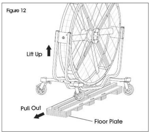
text_image
Figure 12 Lift Up Pull Out Floor PlateTILT KNOB AND HANDLE ASSEMBLY
-
Loosen the screws from the frame tubing using a Phillips screwdriver. Insert the tilt knobs and tighten the screws. (See Figure 13)
-
Three handle mounting holes are located on each side. Select preferred handle height. Align handles with mounting hole on side of frame tubing and turn clockwise to tighten them. (See Figure 13)
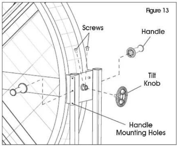
text_image
Figure 13 Screws Handle Tilt Knob Handle Mounting HolesCONTROL BOX ASSEMBLY
- Loosen screws from mounting plate using a 10 mm wrench or Phillips screwdriver. Align control box with the loosened screws on mounting plate and slip the control box over the screws using key hole slots on control box. Re-tighten screws. (See Figure 14)
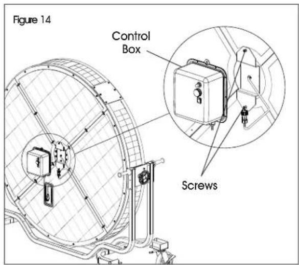
text_image
Figure 14 Control Box ScrewsASSEMBLY CONTINUED
- Insert the power connector to the control box. (See Figure 15)
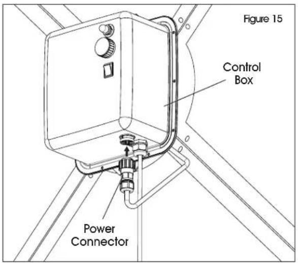
text_image
Figure 15 Control Box Power ConnectorOPERATION
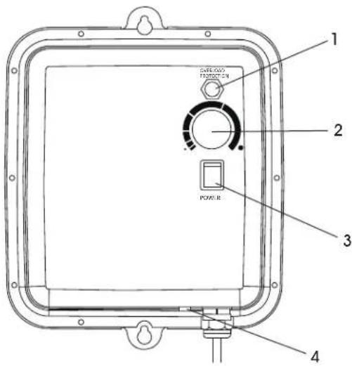
text_image
1 2 3 4 POWER- Switch on fan with power switch.
- Turning knob clockwise will increase fan speed. Turning counterclockwise will decrease fan speed.
- Adjust fan speed to desired output. Turn knob slowly as fan requires time to speed up or slow down.

NOTE: Rotation will always have some natural resonance frequency. This fan has a wide range of speed adjustments which may encounter resonance, causing the fan to vibrate.
| # | DESCRIPTION |
| 1 | Overload Protection |
| 2 | Speed Adjustment Knob |
| 3 | Power Switch |
| 4 | Overheat Indicator |

CAUTION! At a speed where resonance occurs, the whole fan will vibrate somewhat vigorously and with shaking noise. When you notice the fan is vibrating, this may be the resonance. Too much resonance will damage the fan. Skip this speed and the fan will cease vibrating immediately. Resonance is a natural physical phenomenon. Adjust the speed when resonance is observed.
- When the fan is overheated, the overheat indicator will light up. Power off the fan and wait a few minutes until the fan cools down. When the fan cools down to a normal temperature, it is ready for use again.
MAINTENANCE AND CLEANING

WARNING! Parts replacement and troubleshooting should be performed only by qualified personnel.

CAUTION! Do not depend on any switch as the sole means of disconnecting power when installing or servicing the fan. Failure to do so may result in fatal electrical shock.
- Unplug the fan from the wall outlet before servicing or cleaning.

NOTE: There is no user maintenance except regular cleaning as follows. All other servicing or maintenance should be performed by qualified service personnel.
- To clean the fan, use a soft damp cloth. Wipe down with a dry cloth. Do not use cleaners that are harmful to paints or plastics.

CAUTION! Do not use gasoline, benzene, thinner, harsh cleaners, etc., which are dangerous and will damage the fan.

CAUTION! If cleaning requires the removal of a guard, remove only the front guard and re-install when finished in its originally installed position. Do not repair fan blade if it becomes damaged. The fan blade is accurately balanced at the factory and should be replaced if damaged.
- The fan blade, guard and motor should be cleaned periodically to prevent overheating and/or operating in an imbalanced condition.

NOTE: Motor is permanently lubricated.
TROUBLESHOOTING
| OPERATING ISSUE CAUSES RECOMMENDATIONS | ||
| Unit fails to operate. Fan | is not plugged in.Power switch is not on.Electrical outlet is not working property.Unit is damaged or in need of repair. | Ensure fan is plugged in.Move power switch to "ON" position.Check electrical outlet to ensure it is working property.Cease usage and unplug. Contact Uline Customer Service at 1-800-295-5510 for assistance. |
| Air flow is weak or slow. | Air flow is blocked due to an obstruction. | Unplug fan and remove obstruction. Plug fan in and turn it on again. |
| Unit begins to shake. | Considerable vibration. | Adjust to another speed setting.(See Operation on page 6.) |
| Power indicator does not light up when fan is turned ON. Fan does not operate. | Control box power failure. Replace control box. | |
| Fan speed stays low and speed setting knob does not work property. | Control box speed adjustment failure. | Replace control box. |
TROUBLESHOOTING CONTINUED
| OPERATING ISSUE CAUSES RECOMMENDATIONS | ||
| Fan turns on but has significant noise during operation. | Control box driver issue. Replace control box. | |
| Fan can turn ON and works normally for few hours but suddenly stops. Overheat protection red indicator light is lit up on the bottom of the contorl box. | Control box cooling system issue. | Replace control box. |
| Power indicator does not light when fan is turned on. Fan does not operate. | Power failure. Replace control box. | |
| Fan speed remains low after fan is turned on and speed setting knob does not work property. | Speed adjustment failure. Replace control box. | |
| Fan cannot start correctly; fan blade keeps shocking. | Driver issue. Replace control box. | |

NOTE: If you experience a problem with your fan, do not attempt to open or repair the fan yourself. Doing so could damage the fan and/or cause personal injury. Always consult Uline Customer Service at 1-800-295-5510 before further use.
U:IN632
VENTILADOR MÓVIL JUMBO
800-295-5510
uline.mx
natural_image
Technical line drawing of a large industrial fan with multiple blades and wheels (no text or symbols)DATOS TÉCNICOS
text_image
Technical diagram of a fan with numbered components labeled 1 through 5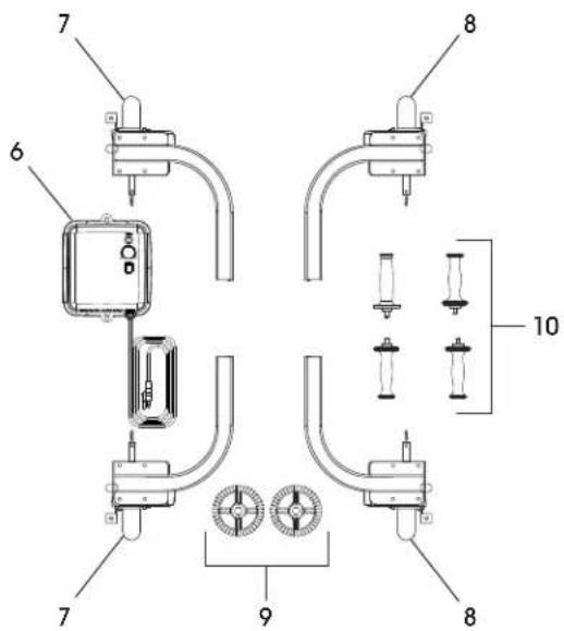
text_image
Technical diagram of a mechanical or electrical device with numbered components and labeled partsnatural_image
Technical line drawing of a mechanical device with internal components and external supports (no text or symbols)natural_image
Mechanical clamp mechanism diagram showing a curved arm and wheel assembly (no text or symbols)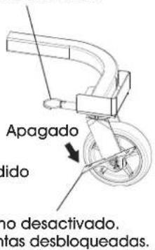
natural_image
Technical line drawing of a large industrial fan with multiple blades and wheels (no text or symbols)DONNÉES TECHNIQUES
text_image
Technical diagram of a fan with numbered components, showing internal blades and mounting brackets.