
H-7096 - Fan Uline - Free user manual and instructions
Find the device manual for free H-7096 Uline in PDF.

User questions about H-7096 Uline
0 question about this device. Answer the ones you know or ask your own.
Ask a new question about this device
Download the instructions for your Fan in PDF format for free! Find your manual H-7096 - Uline and take your electronic device back in hand. On this page are published all the documents necessary for the use of your device. H-7096 by Uline.
USER MANUAL H-7096 Uline
ULINE H-7096, H-7097 HEAVY-DUTY WALL MOUNT FAN – STATIONARY
TOOLS NEEDED
7/16" Wrench (2)
9/16" Wrench (2)
1-800-295-5510
uline.com
natural_image
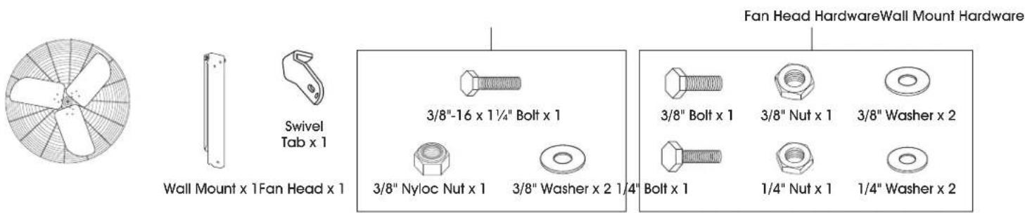
Technical line drawing of a large industrial fan with visible blades and central hub (no text or symbols)PARTS
text_image
Swivel Tab x 1 Wall Mount x 1 Fan Head x 1 3/8"-16 x 1¼" Bolt x 1 3/8" Nyloc Nut x 1 3/8" Washer x 2 1¼" 3/8" Bolt x 1 3/8" Nut x 1 3/8" Washer x 2 Bolt x 1 1/4" Nut x 1 1/4" Washer x 2 Fan Head Hardware Wall Mount HardwareSAFETY

CAUTION! Read all instructions carefully before attempting to assemble, install, operate or service the product. Failure to comply with instructions could result in personal injury and/or property damage. Using this product for any other purpose than it was intended, or not within the operating specifications in these instructions will void the warranty and may cause damage to the fan or serious injury to personnel.

WARNING! To reduce risk of fire, electric shock or personal injury:
- This fan is intended for general use only. Do not use near hazardous or explosive materials or vapors.
- Before operating this fan, check for worn, damaged or missing parts and replace or repair as needed.
- Disconnect from power source before servicing.
- Never insert fingers or any other objects through the guards when fan is in operation.
-
Never operate fan without guards in place.
-
Certain fans have guards that are not OSHA compliant. These units are designed to be intrinsically safe; however, never allow children near fan when in operation. Uline recommends these fans be installed greater than 7' from the ground.
- Unplug the fan before moving from one location to another.
- Fan must be located in an area that allows for adequate airflow around the fan. Starving the fan of air may cause motor to overheat and trigger the unit to shut off.
- Fan motor is thermally protected and will shut off if overheated. Turn unit off and allow motor to cool before restarting.
- Carefully read all safety messages in these instructions and on equipment safety labels.
- Warning labels must be kept in good condition and be replaced if necessary.
- Follow recommended precautions and safe operating practices.
- Suitable for damp locations; GFCI is required.
SAFETY CONTINUED
- Do not use this fan with any speed control device unless otherwise noted.
- Before operating, always check fan for loose or damaged parts. Inspect power cord for damage. Never use fan without safety guards attached.
- Operate only on 120 volt 60 Hz (cycle) current with a minimum 15 amp circuit.
- When used with an extension cord, use a UL-listed, 14 AWG cord equipped with a receptacle to accept the three-prong grounded plug on the fan's power cord and a 3-prong grounded plug for the power source. If extension cord is longer than 50', consult with cord manufacturer for proper cord AWG rating. Always keep power cord and extension cords away from heat, oil and sharp edges. Inspect cords periodically and replace if damaged.
- For general ventilating use only. Do not use to exhaust hazardous or explosive materials and vapors. Never use the fan in spaces which contain products such as gasoline, solvents, paint thinners, dust particles, volatile or airborne combustibles, or any unknown chemicals.
STOP
WARNING! To reduce the risk of fire, electric shock or injury to persons, do not use replacement parts that have not been recommended by the manufacturer (e.g. parts made at home using a 3D printer).
- To reduce the risk of electric shock and injury to persons, do not use in a window.
- Do not move the fan while operating. Moving fan during operation can cause blade damage.
- To guard against electric shock while operating, do not allow fan to come in contact with other grounded objects such as pipes, radiators, etc. Risk of fire, electric shock or personal injury when performing service or maintenance. Unplug or disconnect the fan from the power supply before servicing.

CAUTION! Automatically operated device. To reduce the risk of injury, disconnect from power source before servicing.

CAUTION! All electrical work should be completed by qualified electrician and meet all national, state and local codes.
WIRING
Fans come pre-wired with 120V three-prong power cord:
- The power source must conform to the electrical requirements of the fan.
- The power cord has a three-prong grounded plug that must be plugged into a GFCI (Ground Fault Circuit Interrupter) protected circuit.
- Do not alter the plug to remove the grounding prong and never use a two-prong adapter.
- Replace damaged or worn power cords immediately.
- Where possible, avoid using extension cords. If one must be used, the cord must be UL listed, be the proper size (Amp rating) and have three-prong grounded connections.
Fans are not factory-wired (customer-supplied power cord or hard-wired installations):
- Wiring should only be done by a trained electrician to prevent injury or death.
- Configure internal wires to match supply voltage and wire according to motor nameplate. Test to verify correct rotation.
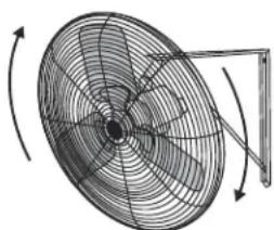
- Many of the electric motors are reversible. Ensure fan is rotating in the proper direction. Blade must spin clockwise when viewing the fan as shown with the blade in front and motor in back. (See Figure 1)
Figure 1
natural_image
Diagram of a fan with rotating blades and a stand, showing no text or symbolsBlade Rotation
- Follow instructions on the motor label to change rotation if necessary.
- It is recommended to install a lockable disconnect switch near each fan.
- Route wire to motor with drip loop and secure. Drip loop will drain accumulated moisture away from motor.
SAFETY CONTINUED
- Only permit power to unit when motor cover plate and all guards are properly installed to prevent injury.

WARNING: This product can expose you to chemicals, including lead and lead compounds, which are known to the State of California to cause cancer and birth defects or other reproductive harm. For more information go to www.P65Warnings.ca.gov.
INSTRUCTIONS
UNPACKING FAN
Inspect the unit for any damage that may have occurred during shipping.
Contact Uline Customer Service at 1-800-295-5510 immediately if any damage is found.

NOTE: Wall mounts must be installed on a support structure strong enough for the added weight of the mount and fan assembly. User is responsible for determining that their structure is adequate to support these loads.
MOUNTING HARDWARE
The hardware to attach the fan mount to the support structure is not supplied. Hardware must be adequately sized and be the proper type for installation to safely support the fan. Always follow the fastener manufacturer's installation instructions.
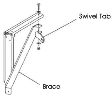
WALL BRACKET ASSEMBLY
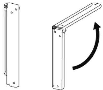
- Unfold pre-assembled brackets. Visually inspect hinge bolt to ensure threads are protruding past the nyloc nut. Tighten nut if needed. (See Figure 2)
Figure 2
natural_image
Technical line drawing of two metal bracket components with mounting holes and a curved arrow indicating rotation (no text or symbols)- Install brace and swivel tab onto top part of unfolded pre-assembled bracket with 3/8"-16 x 1¼" bolt, 3/8" washers and 3/8" nyloc nut using two 9/16" wrenches. (See Figure 3)

NOTE: Tighten until swivel tab is seated against bracket, but still allows rotational movement.
Figure 3
text_image
Swivel Tab BraceATTACHING FAN TO MOUNT
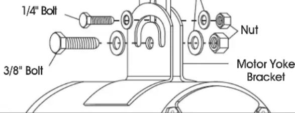
Use the supplied hardware to attach fan to the mount. The 3/8" bolt installs through the center hole of the motor yoke bracket. The 1/4" bolt fastens through the slot feature. Adjust fan to desired angle and securely tighten all nuts. (See Figure 4)

NOTE: Bolts should be installed with a washer on either side of the motor yoke bracket.
Figure 4
text_image
1/4" Bolt 3/8" Bolt Nut Motor Yoke BracketINSTRUCTIONS CONTINUED
Fan mount designs may vary. Fan must always be attached to the mount through center hole of the motor yoke bracket using 3/8" bolt.

CAUTION! Nuts may loosen over time. It is important to check and tighten fasteners frequently.

CAUTION! Inspect fan components and fasteners frequently for corrosion. Replace any corroded fasteners or parts.
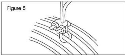
SAFETY CABLE
A secondary support cable (not included) should be installed anytime the fan is mounted overhead for additional safety. (See Figure 5)

NOTE: Safety cable must go around the large diameter wires of front and rear guards.
Other end of safety cable must be securely fastened to a building joist, truss or beam near the fan. Take up all necessary slack in the cable. (See Figure 5)
natural_image
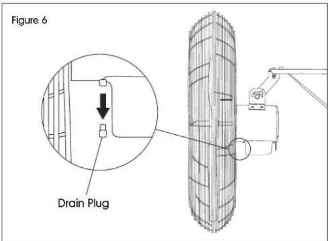
Diagram of a rope knot being inserted into a wire, labeled as Figure 5 (no text or symbols on the diagram itself)REMOVING MOTOR DRAIN PLUGS
After installing the fan, remove the motor drain plug located at the lowest point of the motor.

NOTE: Failure to remove the drain plug may allow condensation to build up inside the motor, reducing motor life, and will void the warranty. Do not remove drain plugs on top side of the motor.
Drain plug locations and quantity may vary by motor design. (See Figure 6)
text_image
Figure 6 Drain PlugMAINTENANCE

WARNING! Disconnect power before cleaning or maintaining fan in order to prevent serious injury or death.
- Some maintenance procedures may require removal of fan guarding.
• After servicing, guards and other safety devices must be reinstalled to their original condition. -
Excessive dust and debris may cause overheating and reduced fan performance.
-
Keep guards, motor and blades clean by vacuuming or wiping with a damp cloth.
- Do not use harsh chemicals or cleaners to clean any part of the fan.
- Pressure washing the unit will void the warranty.
- Sealed motor bearings are pre-lubricated and do not require servicing.
TROUBLESHOOTING
| OPERATING ISSUE CAUSES RECOMMENDATIONS | ||
| Fan does not operate. | Fan is not plugged in. Blown fuse or tripped circuit breaker. Defective on/off switch. Defective motor. Fan blade contacting housing. | Check power cord connection. Replace fuse or reset circuit breaker. Repair or replace switch. Repair or replace motor. Realign fan blade in fan housing. |
| Insufficient airflow. | Guards excessively dirty. Blade and motor excessively dirty. | Clean inlet and outlet guards. Clean blade and motor. |
| Excessive noise. | Fan blade contacting housing. Defective motor bearings. Loose guards. | Realign fan blade in fan housing. Repair or replace motor. Tighten guard fasteners. |
| Excessive vibration. | Damaged fan blade. Motor shaft is bent. Motor is loose. | Replace fan blade. Repair or replace motor. Realign if necessary and tighten fasteners. |
ULINE H-7096, H-7097
VENTILADOR DE PARED PARA USO PESADO – FIJO
natural_image
Technical line drawing of a large industrial fan with multiple blades and a mounted bracket (no text or symbols)PARTES
natural_image
Diagram of a fan with internal blades and directional arrows indicating rotation (no text or labels)natural_image
Technical line drawing of two metal bracket components with mounting holes and a curved arrow indicating rotation (no text or symbols)natural_image
Technical line drawing of a large industrial fan with visible blades and central hub (no text or symbols)PIÈCES
natural_image
Diagram of a fan with internal blades and rotating arm (no text or symbols)Rotation des pales


