
H-1408 - Fan Uline - Free user manual and instructions
Find the device manual for free H-1408 Uline in PDF.

User questions about H-1408 Uline
0 question about this device. Answer the ones you know or ask your own.
Ask a new question about this device
Download the instructions for your Fan in PDF format for free! Find your manual H-1408 - Uline and take your electronic device back in hand. On this page are published all the documents necessary for the use of your device. H-1408 by Uline.
USER MANUAL H-1408 Uline
natural_image
Line drawing of a four-bladed outdoor fan mounted on a stand (no text or symbols)TOOLS NEEDED
Phillips
Screwdriver
10 mm Socket Wrench
11 mm Socket Wrench
19 mm Socket Wrench
PARTS

Fan Head x 1
Base x 1
Top
Pedestal x 1
Bottom
Pedestal x 1
Zip Tie x 2

19 mm Bolt x 1

11 mm Bolt x 1

10 mm Bolt x 5

19 mm Nut x 1

11 mm Nut x 1

11 mm Washer x 1

19 mm Lock
Washer x 1

11 mm Lock
Washer x 1

6-32 x 1/4" Screw x 2
SAFETY

WARNING! To reduce risk of fire and electrical shock, do not use this fan with a solid state speed control device. Plug unit into properly rated service outlet.

WARNING! To reduce the risk of fire, electrical shock or injury to persons: Do not use replacement parts that have not been recommended by the manufacturer (e.g. parts made at home using a 3D printer).
• Always unplug unit for cleaning. Wipe with damp cloth and mild detergent.
• Always unplug when not in use.
• Always unplug when moving fan from one location to the next.
- Do not allow unit to become wet or damp.
- Do not add oil. Motor is permanently lubricated.
- Do not put foreign objects through fan guards into blade.
- Do not operate any fan with a damaged cord or plug. Discard fan or return to an authorized service facility for examination and/or repair.
- Do not run cord under carpeting.
- Do not cover cord with throw rugs, runners or similar coverings.
- Do not route cord under furniture or appliances. Arrange cord away from traffic area and where it will not be tripped over.
ASSEMBLY
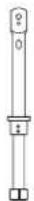
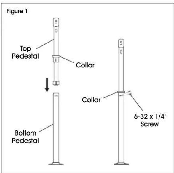
- Remove two 6-32 x 1/4" screws fastened to the collar on the top pedestal. Insert top pedestal into opening of bottom pedestal and align screw holes. Re-insert screws using a Phillips screwdriver to secure the top pedestal to the bottom pedestal. (See Figure 1)
text_image
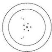
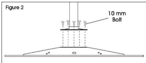
Figure 1 Top Pedestal Collar Bottom Pedestal Collar 6-32 x 1/4" Screw- Remove five 10 mm bolts fastened to the base using a 10 mm socket wrench. Use same bolts to secure the assembled pedestal to the base. Tighten with 10 mm socket wrench. (See Figure 2)

NOTE: Do not use a drill. This could cause the bolts to cross-thread.
text_image
Figure 2 10 mm Bolt-
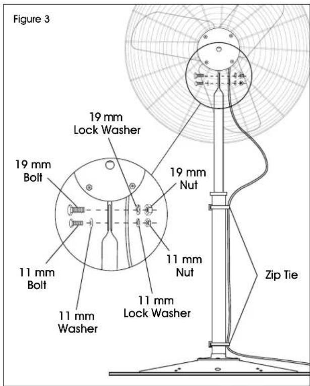
Align fan head with mounting holes on assembled pedestal. Use 19 mm bolt, lock washer and nut to secure through top hole. Use 11 mm bolt, washer, lock washer and nut to secure through bottom crescent slot. Tighten with 19 mm and 11 mm socket wrenches. (See Figure 3)
-
Secure power cord from the motor to the bottom of the pedestal using two zip ties. (See Figure 3)
text_image
Figure 3 19 mm Lock Washer 19 mm Bolt 11 mm Bolt 11 mm Washer 11 mm Nuts 19 mm Nuts 11 mm Lack Washer Zip TieOPERATION
OSCILLATING (FOR H-1407, H-1408)
Push up lever to stop fan from oscillating and pull down to start again. (See Figure 4)
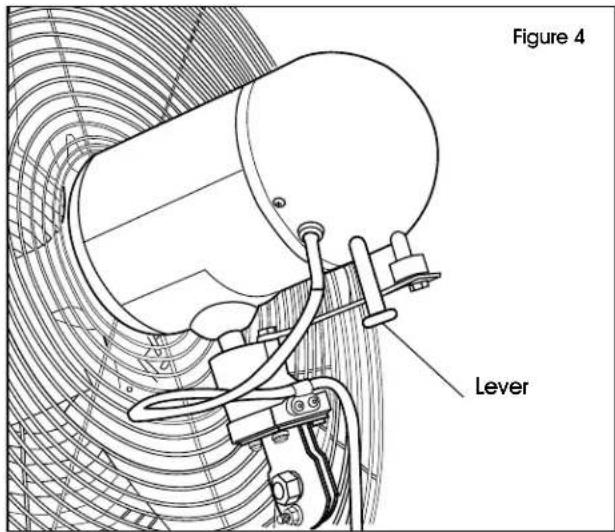
text_image
Figure 4 LeverVENTILADOR DE PEDESTAL
natural_image
Line drawing of a standard office air conditioner with a circular fan and three blades mounted on a stand (no text or symbols)PARTES
natural_image
Line drawing of a standard office fan with a four blades mounted on a stand (no text or symbols)OUTILS REQUIS
Tournevis cruciforme


