
H-4604 - Scale Uline - Free user manual and instructions
Find the device manual for free H-4604 Uline in PDF.

User questions about H-4604 Uline
0 question about this device. Answer the ones you know or ask your own.
Ask a new question about this device
Download the instructions for your Scale in PDF format for free! Find your manual H-4604 - Uline and take your electronic device back in hand. On this page are published all the documents necessary for the use of your device. H-4604 by Uline.
USER MANUAL H-4604 Uline
H-10905, H-10906, H-10907
STAINLESS STEEL
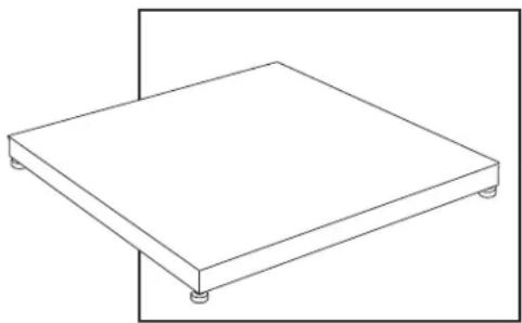
LOW PROFILE FLOOR SCALE
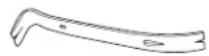
TOOL NEEDED
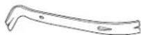
Pry Bar
1-800-295-5510
oline.com
Select a site for the floor scale where it is least likely to be damaged by forklifts and other material handling devices. Floor scale load cell weighing elements are prone to overload damage caused by side impacts, falling objects and weight loads that exceed the rated capacity of the scale.
Site should be:
- Level within 1/4 .
Free from vibration.
Clean of debris. - Out of the way of vehicle traffic patterns, unless installed in a pit while having a rated capacity that exceeds all loaded vehicle weights that could possibly drive onto or contact the scale.
The cable from the floor scale to the digital weight indicator should be run through a conduit to protect it against possible damage. Running the instrument cable through a conduit is the best method of protection.
UNPACKING
- Inspect your shipment for damage. If you see visible signs of damage, notify carrier at once.
- Remove floor scale from the shipping pallet. Digital indicator and power cord should be attached.
- Remove feet from package.
FEET INSTALLATION AND LEVEL ADJUSTMENTS

NOTE: Scale is shipped without feet installed to protect against damage in transit.
- Using a pry bar, lift scale up and thread feet into the cells counterclockwise.
- Screw feet until top of the threaded stem is flush with top of the cell.

NOTE: Do not screw feel more than ten turns.
- Place the scale on the ground to check if scale is level and that all four feet are solid on the ground.
- Make adjustments as needed if scale is not level.
- Once level, tighten locknuts on feet to lock into place.
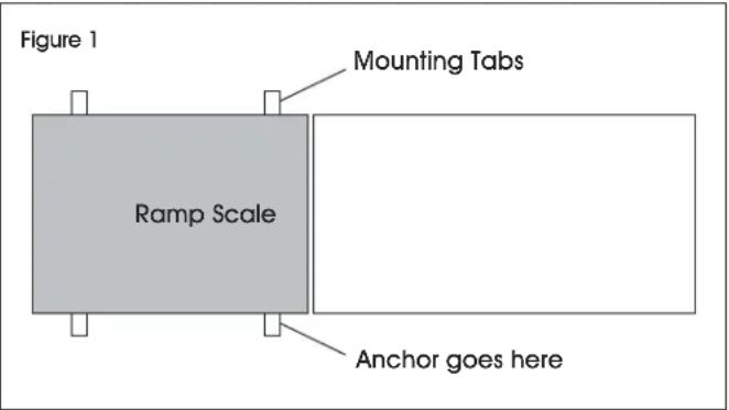
RAMP INSTALLATION (OPTIONAL)
- Set floor scale in desired location.
- Position ramp on desired side of the scale. There should be 1/8 - 1/4 gap between the scale and ramp. (See Figure 1)
- To hold ramp in place, drill 1/2 × 3 anchors (not included) through ramp's mounting tabs into the floor.

NOTE: Scale and ramp should not be touching. Contact will impede scale from weighing accurately.
PARTS DIAGRAM
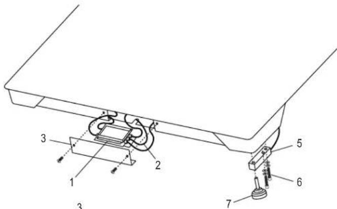
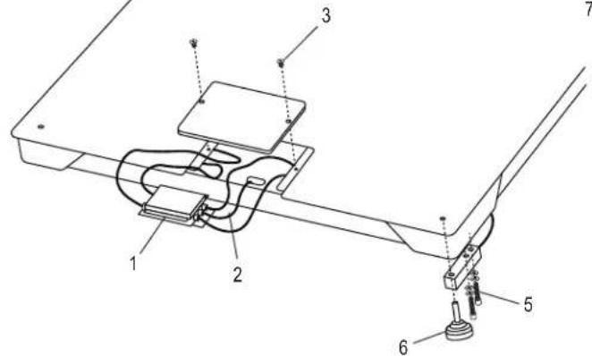
| # | DESCRIPTION | QTY. | ULINE PART NO. | MFG. PART NO. |
| 1 Top Access/Mild Steel Four-Cell Box and Card 1 H-754-53081 53081 | ||||
| 2 Top Access/Instrument Cable LP-7510 Quick D | 1 | H-754-7510CB | 65088 | |
| 3 Cable Top Access/Mild Steel Plate and Screws 2,500-10,000 lb. | 1 | H-756-2936 | 2936 | |
| 5 Top Access/Tool Steel Load Cell 2,500 lb. and 5,000 lb. Base | 4 | H-5259 | 2995 | |
| 5 Top Access/Tool Steel Load Cell 10,000 lb. Base | 4 | H-5260 | 2997 | |
| 6 Top Access/Load Cell Bolts and Washers 2,500-10,000 lb. | 8 | -------- | 29350 | |
| 7 Top Access/Load Cell Foot 2,500-10,000 lb. Base | 4 | H-754-5043 | 5043 | |
| 8 Stainless Steel Display Indicator LP-7510A | 1 | H-4602-65082 | 65082 | |
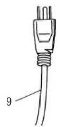
| 9 Power Cord | 1 | H-8001 | 65081U |
ASSEMBLY
SETUP INSTRUCTIONS

NOTE: Floor scale is shipped without the four threaded leveling feet installed to protect against damage. See page 1 for feet installation and level adjustments.
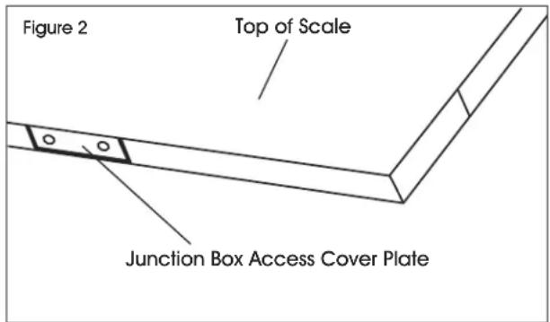
- Remove the screws from the junction box access cover plate and remove cover plate. (See Figure 2)
- Find the instrument cable inside this compartment. Route the cable from inside through the opening in the backside of tray and out from under scale into digital weight indicator.
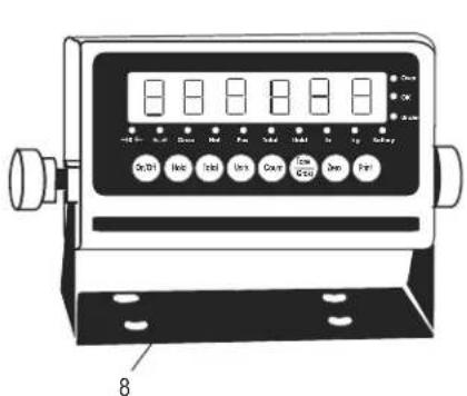
- Plug instrument cable connector into the digital weight indicator. (See Figure 3)
- Plug 110V power plug from the digital weight indicator into a 110V wall socket. (See Figure 3)
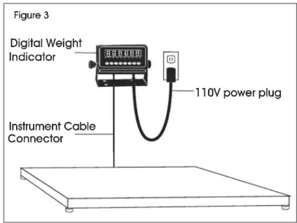
- Press the power button located on the front of the indicator. The scale will automatically turn on when plugged in. The scale is ready to weigh.
MODEL/SERIAL NUMBER LOCATIONS
The model identification label is located on the side of the frame, next to the junction box access plate. Include both model number and serial number when making inquiries or ordering parts.
CALIBRATION
This scale was calibrated at the factory. DO NOT ATTEMPT TO CALIBRATE THIS SCALE.

WARNING! Breaking, removing or tampering with the lead seal that locks out the calibration switch on the digital weight indicator will void all warranties. Calibration is performed by certified scale service agencies only.
Contact your local weights and measures service agency for calibration services.
DISPLAY INDICATOR AND FUNCTION KEYS
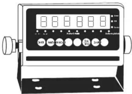
The display indicator utilizes an LED (Light Emitting Diode) display. LEDs are used indoors where brightness is needed. The tables below summarize the LED and key functions.
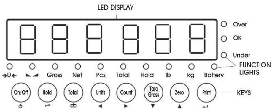
LED FUNCTIONS
| LED | INSTRUCTION |
| →0← | Weight is zero |
| The weighing data is stable | |
| Gross | Gross weight |
| Net | Net weight |
| Pcs | Show the counting status |
| Total | Go to accumulation mode |
| Hold Data hold | |
| Ib | Ib |
| kg | kg |
| Battery | Flash Red = Low Red = Charging Green = Full |
| Over | Overload |
| Ok | Ok |
| Under | Underload |
KEY FUNCTIONS
| KEY KEY | NAME KEY FUNCTION | |
| ON/OFF | Power On/Off Press for two seconds to power on or power off. | |
| Hold | Hold Weight | Four hold functions; can be changed in parameter settings. See operation section for instructions.→ Toggle |
| Total | Accumulation | Works with PRINT key to perform the accumulation function and check the accumulation result. Save |
| Units | Lb/Kg Convert | Convert between lb and kg.← Left |
| Count | Counting | Counting Operation.→ Right |
| Tare/Gross | Tare/Gross Weight | Press key once to dare. Press key again to get Gross Weight.→ Down |
| Zero | Zero | Zeros the weight within tolerance.▲Up |
| Works with ZERO, TARE, ON/OFF keys to perform functions.← Enter | ||
OPERATION
POWER ON/OFF
- Pressthe ON/OFF key for two seconds to turn the scale on or off.
- When turning on, the indicator will show 000000-999999 before entering weighing mode.
- Check that the LED display and the status lights are working properly.
ZERO
INITIAL ZERO SETTING
When turning the scale on, if the weight on the display indicator is within the initial zero tolerance, the indicator will show .
MANUAL ZERO SETTING
- Wait for the scale to stabilize.
- Press the ZERO key. The display will show zero weight.
HOLD FUNCTIONS
There are four different hold functions.
PEAK HOLD
Captures the highest weight.
- Press the HOLD key then add weight to the scale.
- The highest recorded weight will show on the display until a higher weight is placed on the scale.
MANUAL HOLD
Captures and holds the current weight so it will not change/fluctuate.
1. While weighing, press HOLD. The current weight will show on the display until HOLD is pressed again.
AUTO HOLD
If the current weight is above 20d (20 x division) and is stable, the current weight will be displayed for three seconds then go back to general weighing.
- Pressing the HOLD key is unnecessary. Auto Hold is done automatically when the scale is stable.
AVERAGE HOLD
Used for animal weighing. The indicator will display the average weight sampled for three seconds.
- Add livestock to scale and press HOLD.
- "LOC" will be displayed for three seconds. Then the average weight will be displayed.
- Press HOLD again to exit holding mode.
TARE/GROSS
- Press the TARE/GROSS key.
- The indicator will show the net weight. The Net and Tare function lights will light up.
- Press the TARE/GROSS key. Zero the weight.
- The indicator will display the gross weight.
ACCUMULATION
- Zero the weight. Load weight until the scale stabilizes.
- Press the TOTAL key to enter accumulation mode.
- Total function light will light up. Display will read 001 then will display the loaded weight.
- Unload the weight. Zero the weight. Load the second weight until the scale stabilizes.
- Press the TOTAL key. The display will read n002, then display the second loaded weight.
- Repeat a maximum of 999 times.
CHECK THE ACCUMULATION
- Press and hold the PRINT key. Press the TOTAL key.
- Display will read n^** , then will show total weight.

NOTE: There are eight digits total. The display shows the first four digits, then the last four digits. For example, when the first four digits displayed are "0012" and the last four digits displayed are "34,56," the weight is "1234.56."
EXIT ACCUMULATION
- When the indicator shows the last four digits, press and hold the TOTAL key. The indicator will read cir n.
- Press the PRINT key to exit. If you want to clear the total weight, press the ZERO or TARE key. The indicator will read clear .
- Press the PRINT key to clear the total weight and exit accumulating mode.
- If the weight is stable, connect the scale to the printer.
- Press the PRINT key.

NOTE: While in tare mode, print with tare. If the scale shows a negative weight, printing is not allowed.
OPERATION CONTINUED
COUNTING
Use this mode to count parts of uniform weight.
- In weighing mode, remove all weight from the platform.
- Press the COUNT key to enter the counting mode. P C S will be shown on the display.
- Press the ZERO key to change the sample quantity -5, 10, 20, 50, 100, 200 or 500 units.
-
Place the sample quantity of the item being counted on the scale platform and press the PRINT key. Sample quantity will be shown on the display.
-
Place remaining objects on the platform. The total quantity will be shown on the display.
- Press the COUNT key to return to weighing mode.
- To weigh different weights, at weighing mode put the item on the scale and press the COUNT key. The indicator will read 0.
- Press and hold the Count key. Press the ON/OFF key. The indicator will show PC5 .
- Press the ZERO key and input the sample quantity.
- Press the PRINT key to enter. Repeat steps 2 and 3.
TROUBLESHOOTING
POSSIBLE TARE OPERATION CODES
| ERROR REASON | SOLUTION | |
| UUUUUUUU Weight | overload. Bad connection with load cell. Load cell has quality problem. | Reduce the weight. Check load cell connection. Inspect load cell. Check input and output. |
| nnnnnnn Calibration error. | Bad connection. Load cell has quality problem. | Check that scale is level. Check load cell connection. Inspect load cell. Check input and output. |
MAINTENANCE
- Protect the display indicator from direct sunlight.
- Maintain a good connection between load cell's instrument cable connector and indicator.
-
Keep indicator away from strong electric and magnetic fields.
-
Power off the indicator during electrical storms.
- Power off the indicator before plugging and unplugging.

H-4602, H-4603, H-4604
H-10905, H-10906, H-10907
BÁSCULA DE ACERO INOXIDABLE DE PERFIL BAJO PARA PISO
H-10905, H-10906, H-10907
BALANCE DE PLANCHER A ULINE.C PROFIL BAS EN ACIER INOXYDABLE
1800295-5510
uline.ca
OUTIL REQUIS
Levier


