
H-4709 - Forklift Uline - Free user manual and instructions
Find the device manual for free H-4709 Uline in PDF.

User questions about H-4709 Uline
0 question about this device. Answer the ones you know or ask your own.
Ask a new question about this device
Download the instructions for your Forklift in PDF format for free! Find your manual H-4709 - Uline and take your electronic device back in hand. On this page are published all the documents necessary for the use of your device. H-4709 by Uline.
USER MANUAL H-4709 Uline
natural_image
Line drawing of a pallet jack mechanism (no text or symbols)SAFETY
SAFETY SYMBOLS
WARNING and CAUTION are both signal words intended to alert the viewer to the existence and relative degree of a hazard.

Warning indicates a hazard that could result in injury or death if proper precautions are not taken.

Caution indicates a reminder of routine safety practices.
SAFETY PRECAUTIONS

WARNING! Do not operate this truck unless you have been trained and authorized to do so and have read all warnings and instructions in the operator's manual and on this truck.

WARNING! Do not operate this truck until you have checked its condition. Give special attention to the wheels, horn, battery, controller, lift system, brakes, steering mechanism, guards and safety devices.

WARNING! Operate the truck only from the designated operating position. Wear foot protection. Do not carry passengers.

WARNING! Observe applicable traffic regulations. Yield right of way to pedestrians. Slow down and sound horn at cross aisles and wherever vision is obstructed.

WARNING! Start, stop, travel, steer and brake smoothly. Slow down for turns and on uneven or slippery surfaces that could cause the truck to slide or overturn. Use special care when traveling without load as the risk of overturn may be greater.

WARNING! Always look in the direction of travel. Keep a clear view. When load interferes with visibility, travel with load or lifting mechanism trailing.

WARNING! Use special care when operating on ramps. Travel slowly and do not angle or turn. Travel with the lifting mechanism downhill.

WARNING! Do not overload truck. Check capacity plate for load weight and load center information.

WARNING! Do not handle loads that are higher than the load backrest or load backrest extension unless load is secured so that no part of it could fall backward. Before lifting, ensure load is centered, forks are completely under load and load is as far back as possible against load backrest.

WARNING! When leaving truck, neutralize travel control, fully lower lifting mechanism, set brake and shut off power when leaving truck unattended.
MOVING A DISABLED TRUCK

WARNING! Do not attempt to move a disabled truck. Notify your supervisor or proper authority.
GENERAL INFORMATION
GENERAL DESCRIPTION
H-4709 and H-4710 pallet trucks lift and transport loads on rigid forks.
Controls for steering, braking, forward and reverse travel, horn, lift, lower and speed control are all located on the control handle.
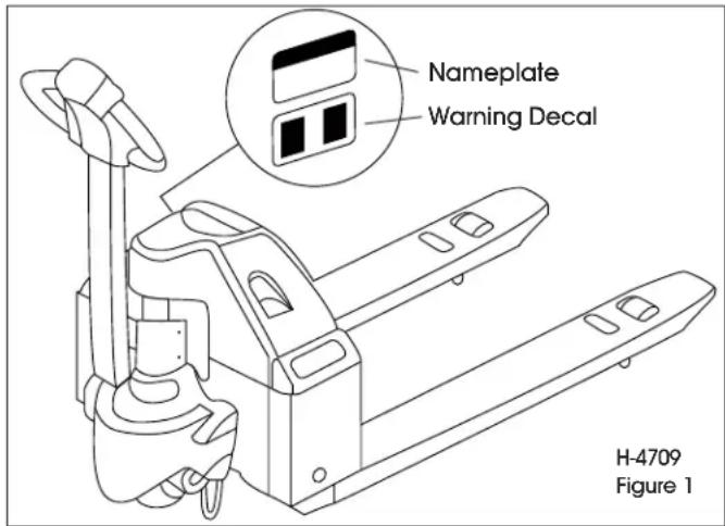
NAMEPLATE AND WARNING DECAL
Nameplate and warning decal locations may vary between models, but they are always near the steering arm, within sight of the operator. (See Figure 1 for H-4709 and Figure 2 for H-4710)
text_image
Nameplate Warning Decal H-4709 Figure 1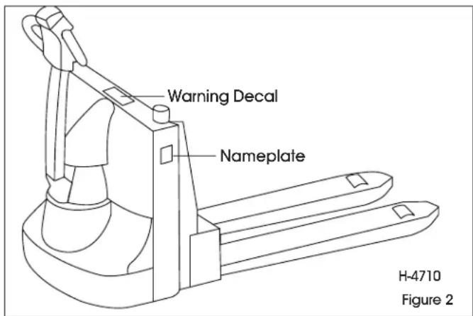
text_image
Warning Decal Nameplate H-4710 Figure 2If the nameplate or warning decal are lost or damaged, they should be replaced immediately. Have your supervisor or the designated authority contact Uline for replacement.
The nameplate shows the model number, serial number, truck type, battery type, voltage, minimum weight and information on load capacity and load center.
The warning decal contains warnings that also appear in this manual.
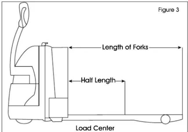
LOAD CAPACITY
Do not overload truck. Check capacity plate for load weight and load center information.
The load capacity depends on the load center. The load maximum capacity listed on the capacity plate assumes a uniform load whose center is at half the length of the fork and centered between the forks. The maximum load capacity is reduced when the load center exceeds half the length of the forks or is not centered between the forks. The fork length and wheelbase must be adequate for the skid or bin to be handled. (See Figure 3)

NOTE: A truck undergoing speed changes is less stable than a standing truck. If you are not sure that the truck can lift a certain load, consult your supervisor or the designated authority.
text_image
Figure 3 Length of Forks Half Length Load CenterOPERATION
BEFORE OPERATION
The Operator Checks table below covers important inspection points on trucks that should be checked prior to operation. Depending on use, some trucks may require additional checks.

WARNING! Periodic maintenance of this truck by a qualified technician is required.
WARNING! A qualified service technician should check the truck monthly for proper lubrication, proper fluid levels, brake maintenance, motor maintenance and other areas.

WARNING! If the truck is found to be unsafe and is in need of repair or if it contributes to unsafe conditions, report immediately to the designated authority. Do not operate the truck until it has been restored to a safe operating condition. Do not make any unauthorized repairs or adjustments. All service must be performed by a qualified service technician.
| OPERATOR CHECKS | |
| ITEM PROCEDURE | |
| Transmission and Hydraulic Systems | Check for signs of fluid leakage. |
| Forks Check for cracks and damage. | |
| Guards and Load Backrest Check that safety guards are properly secured and not damaged. | |
| Safety Signs Check that warning labels, nameplate, etc., are in good condition and legible. | |
| Horn Check that horn sounds when operated. | |
| Steering Check for binding or looseness in steering arm when steering. | |
| Travel Controls Check that speed controls on control handle operate in all speed ranges in forward and reverse and that belly button switch functions. | |
| Wheels Check drive wheel for cracks or damage.Move truck to check load wheels for freedom of rotation. | |
| Hydraulic Controls Check raise and lower operation to their maximum positions. | |
| Brakes Check that brakes actuate when steering arm is raised to upright position and when lowered to horizontal position. | |
| Deadman/Parking Brake | Check that steering arm raises to upright position when released and that brake applies. |
| Battery Disconnect Check that battery can be disconnected and reconnected. Check for connector damage. | |
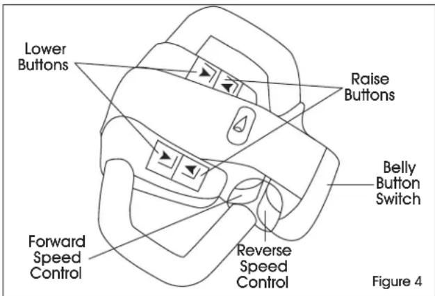
INSTRUMENTS AND CONTROLS
The steering arm and control handle provide controls for steering, forward and reverse speed control, braking, raising and lowering the forks and sounding horn. Control handles on all models have a "belly button" reversing switch that reverses the direction of the truck upon contact with the operator. (See Figure 4)
FORWARD AND REVERSE TRAVEL AND SPEED CONTROL
All directional and speed controls are located on the control handle.
text_image
Lower Buttons Raise Buttons Belly Button Switch Forward Speed Control Reverse Speed Control Figure 4OPERATION CONTINUED
Forward and reverse are controlled by rotating the speed control lever. (See Figure 4) The lever is spring-loaded to return to neutral when released. Further rotation in either direction will progress the truck from slow to maximum travel speed.
To change directions or to stop the truck, rotate the speed control lever in the opposite direction. The truck will come to a stop, and then (unless the controls are returned to the center neutral position) accelerate in the opposite direction.
STEERING
Moving the control handle (which connects to the steering arm) right or left will turn the truck right or left. When maneuvering around corners, make square turns and be sure there is adequate clearance.
STOPPING
Stop the truck as gradually as possible. Unnecessary rapid stopping could be hazardous. Load could become unstable.
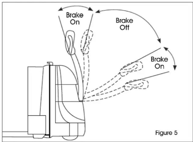
To stop the truck's movement (forward or reverse), raise the control handle to the up position or push the control handle all the way down. In both positions, the electric brake will deactivate and the brake will apply. To release the brake, move the control handle to the operating position. (See Figure 5)

NOTE: The steering arm gas spring automatically raises the steering arm to the upright position when the steering arm is released.

CAUTION! If the control handle does not raise immediately to the upright position when released, the truck should be placed out of service until it can be inspected by a qualified service technician.
flowchart
graph TD
    A["Brake On"] --> B["Car"]
    C["Brake Off"] --> B
    B --> D["Car with Motion"]
    style A fill:#f9f,stroke:#333
    style C fill:#f9f,stroke:#333
    style D fill:#ccf,stroke:#333
PAGE 4 OF 27 0225 IH-4709
PARKING
When parking the truck, do not obstruct traffic lanes or aisles.
- Park the truck in its designated parking area.
- Raise the steering arm until upright to apply the parking brake.
- Fully lower forks.
- Turn key switch to off position.
- Remove key for added security.
- Pull out battery disconnect.
LOAD HANDLING

WARNING! Only handle loads arranged for stability. Always use caution. Raise and lower load smoothly to prevent load from falling.

WARNING! Always ensure load and load center are within the capacity of truck. If in doubt, check nameplate.
- Approach the load slowly.
- Move the truck slowly into position so that the forks are within pallet or skid, the load is centered over the forks and the load is as far back as possible.
- Raise the forks to lift load.
- Lead the truck by the control handle with the load trailing except when in confined areas. Ramps should be traveled with operator uphill of truck when empty and operator downhill of truck with load on forks.
- Always look in the direction of travel. Move slowly and check clearances when approaching obstructions.
- Do not make sudden starts and stops. Operate truck smoothly and gradually.
- Travel slowly and squarely around corners. Remember that the trailing load wheels do not follow the turn path of the drive wheel. Instead, they tend to cut the corner.
- Line up the truck with the unloading area.
- Stop the truck and check the load alignment with surrounding objects.
- Be careful not to damage or move adjacent loads and objects.
- Lower the forks until the load is resting on its own.
- Move the truck back until the forks are clear of the pallet.
CHARGING THE BATTERY (FOR H-4709)

WARNING! This truck is equipped with a battery. Read and heed the warning decal located near the battery.

WARNING! Do not plug into electrical outlet before connecting the battery to the charger. Failure to do so could result in serious injury to operator and product.

NOTE: If pallet truck is not used for a long period of time, charge it no less than once a month.
STEPS MUST BE FOLLOWED IN ORDER:
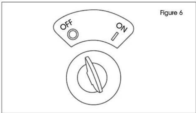
- Turn key to OFF position. (See Figure 6)
text_image
OFF ON Figure 6- Confirm unit is NOT plugged into an electrical outlet.
- Push DOWN emergency shut-off/on switch into the OFF position. (See Figure 7)
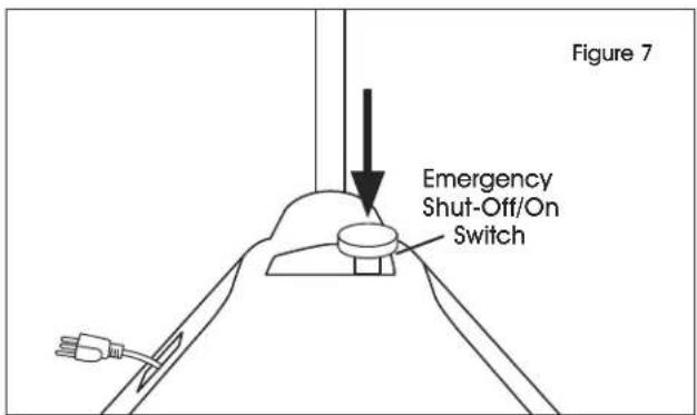
text_image
Figure 7 Emergency Shut-Off/On Switch- Plug truck into electrical outlet to charge battery. (See Figure 8)
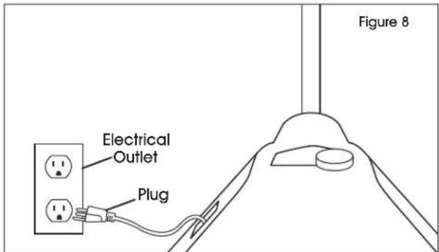
text_image
Electrical Outlet Plug Figure 8- Once charged, unplug truck from electrical outlet.
- Pull UP emergency shut-off/on switch into the ON position. (See Figure 9)
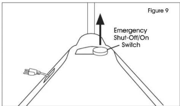
text_image
Figure 9 Emergency Shut-Off/On Switch- Truck is ready for use.
CHARGING THE BATTERY (FOR H-4710)

WARNING! This truck is equipped with a battery. Read and heed the warning decal located near the battery.

WARNING! Do not plug into electrical outlet before connecting the battery to the charger. Failure to do so could result in serious injury to operator and product.
STEPS MUST BE FOLLOWED IN ORDER:
- Turn key to OFF position. (See Figure 10)
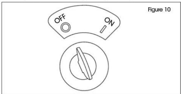
text_image
OFF ON Figure 10- Confirm unit is NOT plugged into electrical outlet.
- Disconnect red battery cable from motor. (See Figure 11)
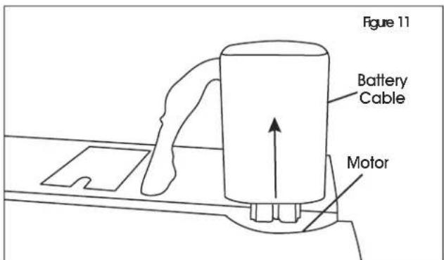
text_image
Figure 11 Battery Cable Motor- Connect red battery cable to charger. (See Figure 12)
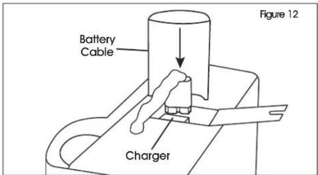
text_image
Battery Cable Charger Figure 12
NOTE: If pallet truck is not used for a long period of time, charge it no less than once a month.
- Plug truck into electrical outlet to charge. (See Figure 13)

text_image
Figure 13 Plug- Once charged, unplug truck from electrical outlet.
- Remove red battery cable from charger. (See Figure 14)
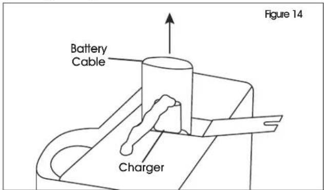
text_image
Figure 14 Battery Cable Charger- Reconnect battery cable to motor. (See Figure 15)
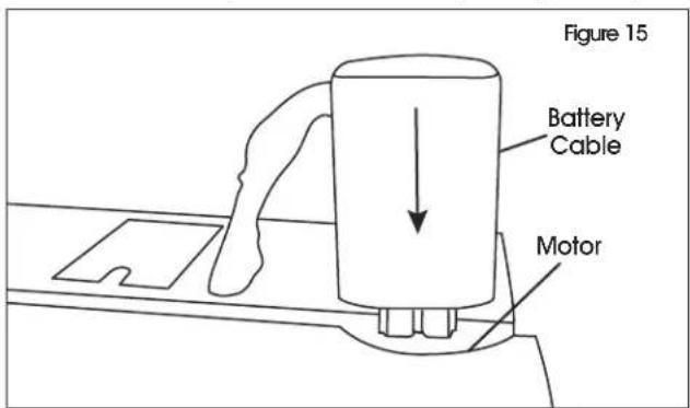
text_image
Figure 15 Battery Cable Motor- Truck is ready for use.
TROUBLESHOOTING
| OPERATING ISSUE PROBABLE CAUSES RECOMMENDATIONS | ||
| Truck will not travel, nor will lift system operate. | Fuse blown.Battery dead or disconnected.Key switch defective.Defective wiring. | Check fuse and replace if necessary.Check battery connections and battery voltage.Bypass key switch to determine if it is malfunctioning.Check for open circuit. Repair as required. |
| Truck does not travel forward or in reverse. All other functions operate normally. | Check all wiring. A loose connection may be the cause of malfunction.Defective deadman switch.Defective controller.Defective potentiometer. | Tighten all loose connections before further troubleshooting.Check and replace switch if defective.Check for proper operation and replace if defective.Check and replace potentiometer if defective. |
| Truck travels forward, but not in reverse.Truck travels in reverse, but not forward.Truck travels forward and in reverse at lower speeds; will not travel at high speed. | Defective potentiometer. Check and replace potentiometer if defective. | |
| Truck does not slow with brake, or brake does not engage. | Defective deadman switch.Defective electric brake. | Check deadman switch for continuity. If none found when the control arm is in the brake position, replace switch.Replace brake. |
| Brake will not release. Brake temperature above 281°F.Open brake circuitry or wiring.Air gap more than 0.01" (0.25 mm)(only for H-4710). | Allow to cool.Make voltage checks.Adjust air gap. | |
| Brake drags.Brake grabs.Abnormal noise and chatter when brake is applied. | Defective electric brake.Air gap more than 0.01" (0.25 mm)(only for H-4710). | Replace brake.Adjust air gap. |
| Oil leaks from the top of the lift cylinder. | Defective packing in lift cylinder. Repair lift cylinder. | |
| Squealing sounds when lifting forks. | Oil level too low.Lift linkage binding. | Add oil to reservoir.Apply grease. |
TROUBLESHOOTING CONTINUED
| OPERATING ISSUE PROBABLE CAUSES RECOMMENDATIONS | ||
| Forks do not lift to top. Oil level too low. | Brake is applied. | Add oil to reservoir. |
| Release brake. | ||
| Weak, slow or uneven action of hydraulic system. | Defective pump or relief valve. | Check pressure. Adjust as needed. |
| Worn lift cylinder. | Replace cylinder. | |
| Load larger than capacity. | Refer to I.D. plate for capacity. | |
| Defective lift motor solenoid. | Replace solenoid on electrical panel. | |
| Battery charge low. | Charge battery. | |
| Forks do not lift, pump motor does not run. | Battery is dead or disconnected. | Check and recharge if required. |
| Defective wiring. | Check and repair as required. | |
| Defect in electrical system for operating pump motor. | Check lift switch in control head and solenoid. Repair or replace as required. | |
| Forks do not lift, motor runs. | Defect in hydraulic system. | Check oil level in reservoir and the oil lines to the lift cylinder and repair as required. If normal, check the hydraulic pump and relief valve. Repair or adjust as required. |
| Lift limit switch not functioning. | Mounting bolt too tight. | Loosen mounting bolt. |
| Out of alignment. | Realign limit switch. | |
| Forks lift, but will not go down. | Defect in hydraulic system. Check | lowering control switch in control head and lowering solenoid on valve assembly. Replace as required. |
| Load will not hold. Oil bypassing internally in control valve. | Worn lift cylinder or packing. | Replace valve assembly. |
| Repack cylinder. | ||
| Forks do not lift to top, pump motor runs. | Oil level too low. | Add oil to reservoir. |
| Load larger than capacity. | Refer to I.D. plate for capacity. | |
| Batteries need charging. | Charge batteries. | |
| Forks creep downward under load when in a raised position. | Leak in hydraulic system, lift cylinder or lowering valve. | Check for leaking fitting in hydraulic line and repair as required. Repack lift cylinder or replace valve assembly. |
| Steering arm does not return to the upright position. | Weak return spring. | Replace spring. |
| Binding. | Check and free the binding item. Verify that the cable has not been damaged. Repair or replace as needed. | |
| Truck moves forward when arm is pulled down. | Deadman switch defective. | Check for short and repair or replace as necessary. |
| Short in control head. | Check wiring and repair as required. | |
TROUBLESHOOTING CONTINUED
| OPERATING ISSUE PROBABLE CAUSES RECOMMENDATIONS | ||
| Steering arm jerks excessively when starting or stopping the truck. | Drive wheel worn. Replace drive wheel if worn to within 3/4" of hub. | |
| Drive motor is jerky. Motor | internally damaged or worn. | Replace motor. |
| Charger will not turn on. Power cord disconnected from charger.Charger defective. | Reconnect power cord to charger.Replace charger. | |
| Batteries will not charge. Loose connections.Batteries run too low. Smart charger cannot detect battery. | Check all connections from charger to batteries.Jump batteries using a trickle charger. | |
natural_image
Line drawing of a manual pallet jack mechanism (no text or symbols)SEGURIDAD
natural_image
Line drawing of a pallet jack mechanism (no text or symbols)SÉCURITÉ
SYMBOLES DE SÉCURITÉ
MANUTENTION DES CHARGES


