H-11553 - Forklift Uline - Free user manual and instructions
Find the device manual for free H-11553 Uline in PDF.

User questions about H-11553 Uline
0 question about this device. Answer the ones you know or ask your own.
Ask a new question about this device
Download the instructions for your Forklift in PDF format for free! Find your manual H-11553 - Uline and take your electronic device back in hand. On this page are published all the documents necessary for the use of your device. H-11553 by Uline.
USER MANUAL H-11553 Uline
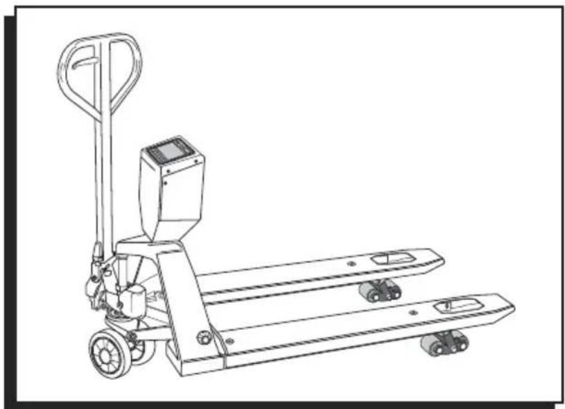
natural_image
Line drawing of a manual pallet jack with control panel and wheels (no text or symbols)GENERAL INFORMATION
Avoid placing the scale in locations that may AFFECT accuracy:
- Temperature extremes – Do not place in direct sunlight or near air conditioning vents.
- Keep scale dry – Do not place in high humidity, damp or wet locations.
- Keep away from air movers like fans or open doors and windows.
- Keep scale clean.
- Do not stack items on the scale when not in use.

WARNING! Scale is not waterproof. Avoid direct contact with water, high humidity and condensation. Do not spray or immerse scale in water. Data may become unstable or scale may malfunction. Turn power off and allow scale to dry before reuse.
H-11553 NTEP PALLET TRUCK SCALE
| MODEL H-11553 | |
| Max. Lifting Weight 5,000 lbs. | |
| Min. Fork Height 313" | |
| Max. Fork Height | 712" |
| Fork Length | 48" |
| Fork Overall Width 27" | |
| Individual Fork Width 7" | |
| Capacity 5,000 lbs. | |
| Division 2 lbs. | |
| External Resolution 1/2,500 | |
| Internal Resolution 1/600,000 | |
| Stabilization Time | 1 Second (Typical) |
| Operating Temperature | 32–104°F |
| Power Supply | External AC adapter, 12V 500mA, built-in rechargeable battery (lead acid, 6V/10Ah) |
| Display | 6 digit LCD digital display with 2" digits (white color LED backlight) |
| Load Cells | 4 Load Cells |
text_image
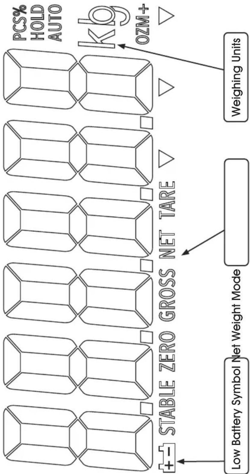
PCS% HOLD AUTO kb OZM+ Stable ZERO GROSS NET TARE Low Battery Symbol Net Weight Mode Weighing UnitsDISPLAY CHARACTERS
| CHARACTER DISPLAY | |
| 0 | 0 |
| 1 | 1 |
| 2 | 2 |
| 3 | 3 |
| 4 | 4 |
| 5 | 5 |
| 6 | 6 |
| 7 | 7 |
| 8 | 8 |
| 9 | 9 |
| A | A |
| B | b |
| C | C |
| D | d |
| E | E |
| F | F |
| G | G |
| H | H |
| CHARACTER DISPLAY | |
| I | 1 |
| J | J |
| K | F |
| L | L |
| M | n |
| N | n |
| O | o |
| P | P |
| Q | 0 |
| R | r |
| S | 5 |
| T | t |
| U | U |
| V | U |
| W | U |
| X | = |
| Y | y |
| Z | 2 |
CONTROLS

primary function

secondary function

ON/OFF Key:
Turn the power on or off.

Zero Key (ZERO):
Zeros display for next weight.

'ENTER' key to set parameters and other functions.

Tare Key (TARE):
Deducts the container weight from pieces weight.

Change number key '^' to set parameters and other functions.

Accumulate Key (M+) :
Adds the value to the accumulation memory. Zero display and press this key to show current total value.

Spaces left '<' to change different numbers on the display. Also used to set parameters or other functions.
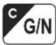
Gross weight/Net weight (G/N):
Toggle between Gross weight and net weight. Display shift is only available after using tare/pretare functions.

Acts as a clear key (C) to reset parameters or other functions.

Pretare Key (PT):
Allows user to manually key in TARE value.

Spaces right '>' to change different numbers on the display. Also used to set parameters or other functions.

Unit Key (U):
Selects weighing units: pounds or kilograms.

Acts as an escape key (ESC) to return the scale to normal operating mode.
ASSEMBLY
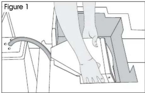
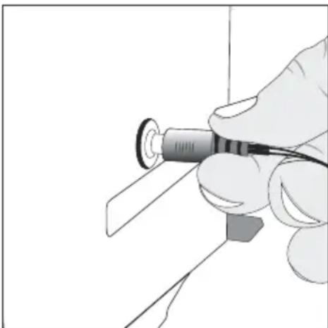
- Remove control panel from packing foam. (See Figure 1)
text_image
Figure 1- Attach control panel. Feed excess cable into the control panel head. Align three holes in control panel with three holes on pallet truck base. (See Figure 2)
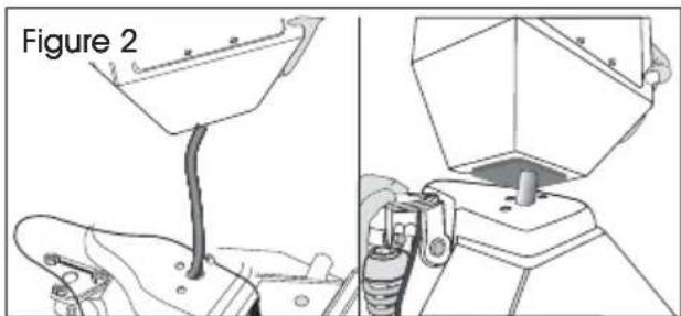
text_image
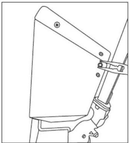
Figure 2- Remove the two screws (one on each side) to release the front panel. Carefully open the front panel. (See Figure 3)
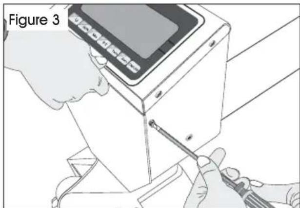
natural_image
Illustration of hands using a screwdriver to adjust or install a device (no text or symbols visible)- Align mounting holes on pallet truck with mounting holes on control panel. (See Figure 4)
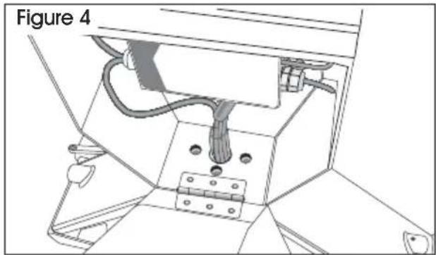
natural_image
Technical line drawing of a mechanical assembly with labeled component 'Figure 4' (no readable text or symbols beyond label)- Insert and tighten 3 hex screws (H109) with spring washers (H110) through base of control panel with hex wrench provided. (See Figure 5)
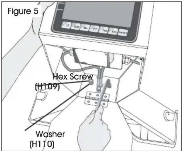
text_image
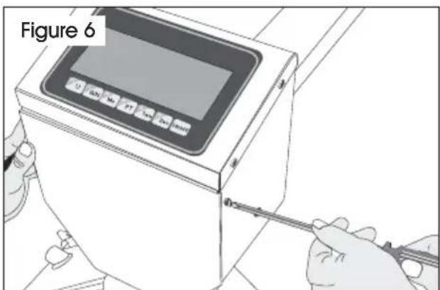
Figure 5 Hex Screw (H109) Washer (H110)- Close front panel and secure with 2 screws. (See Figure 6)
text_image
Figure 6ASSEMBLY INSTRUCTIONS CONTINUED
III. HANDLE INSTALLATION
- Remove handle from protective wrapping.
- Loosen set screw (140) on crank link (139H). (See Figure 7)

text_image
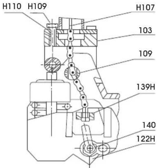
Figure 7 (139H) Set Screw (140)- Remove 3 hex screws (H109) and 3 spring washers (H110) from bottom of handle.
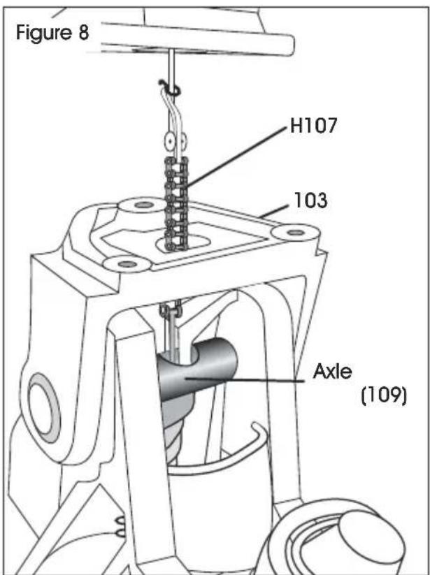
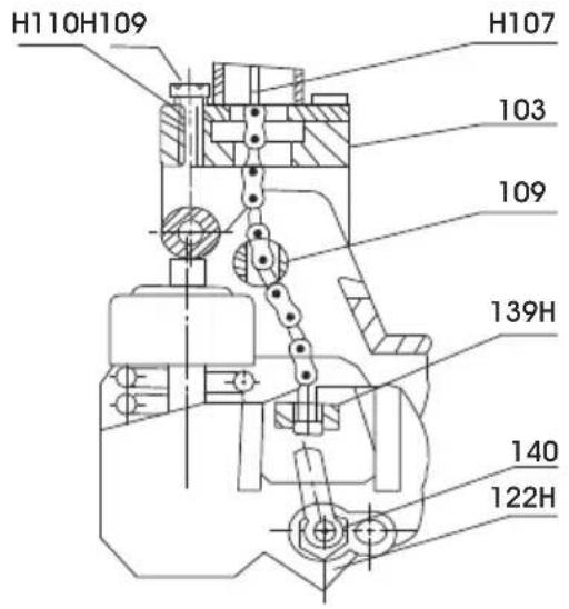
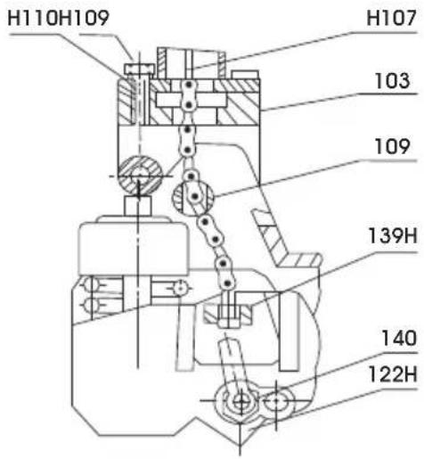
- Feed Wire, Chain and Pin (H107) on bottom of handle through center of base (103) and axle (109). (See Figure 8)
text_image
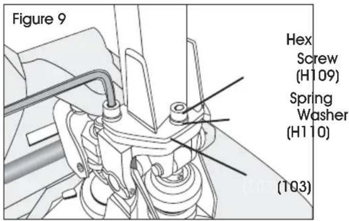
Figure 8 H107 103 Axle (109)- Attach handle to base (103) using 3 hex screws (H109) and 3 spring washers (H110) and tighten with Hex Wrench provided. (See Figure 9)
text_image
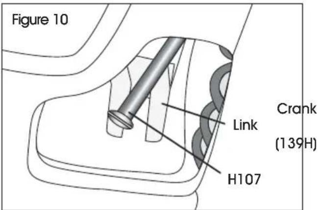
Figure 9 Hex Screw (H109) Spring Washer (H110) (103)- While raising crank link (139H), slide pin of rod and chain (H107) into crank link groove. (See Figure 10)
text_image
Figure 10 Link Crank (139H) H107REFERENCE PARTS DIAGRAMS PAGES 16-19
SAFETY
natural_image
Pure technical line drawing of a mechanical component with no text or symbols
natural_image
Line drawing of a pallet jack with a diagonally extended box (no text or symbols)
natural_image
Simple line drawing of a gray manual pallet jack with handle and base (no text or symbols)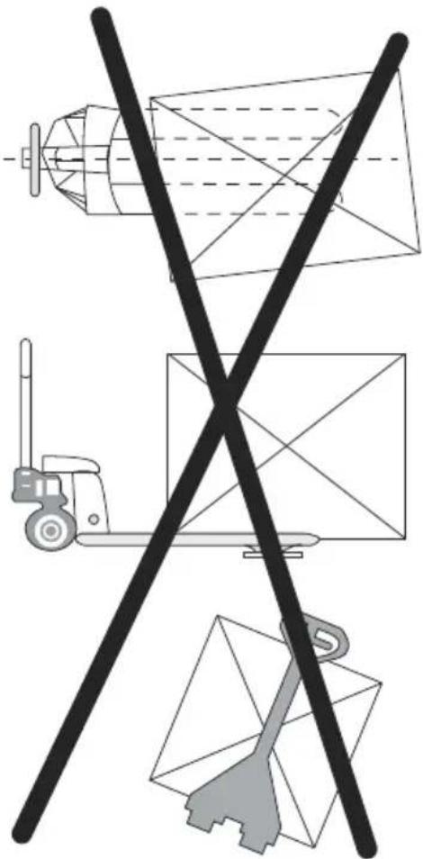
natural_image
Diagram showing a truck, a forklift, and a cargo ship with crossed lines (no text or symbols)SAFETY NOTE
For safe operation of the truck, please read all warnings and instructions in this guide and on the truck before use.
- Do not operate the pallet truck unless you are familiar with it and have been trained or authorized to do so.
- Do not operate the truck unless you have checked its condition. Pay special attention to wheels, handle assembly, forks and controller lever.
- Do not use the truck on sloping ground.
- Never place any part of your body in the lifting mechanism or under the forks or load. Do not carry passengers.
-
It is recommended that operator wears gloves and protective shoes while operating the truck.
-
Do not handle unstable or loosely stacked loads.
- Do not overload the truck.
- The capacity of the truck assumes an evenly distributed load with the center of the load being at the halfway point of the length of the forks.
- Make sure that length of the forks matches the length of the pallet.
- Lower the forks to lowest height when the truck is not being used.
ENSURE FORKS RAISE/LOWER PROPERLY
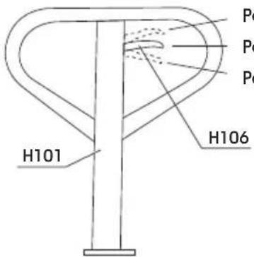
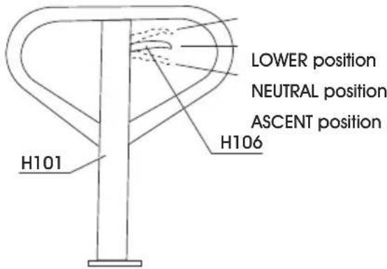
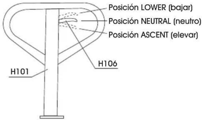
Control Lever (H106) is located on pallet truck handle (H101) and can be set to 3 positions: LOWER, NEUTRAL and ASCENT.
- Tighten set screw (140) on crank link (139H) until LOWER position on Control Lever functions properly. (See Handle Installation Step 2).
- If forks elevate while pumping with Control Lever in NEUTRAL position, turn set screw clockwise until pumping the handle no longer elevates forks and NEUTRAL position functions properly.
- If forks descend while pumping with Control Lever in NEUTRAL position, turn set screw counter-clockwise until forks no longer descend.
- If forks do not descend when Control Lever is in LOWER position, turn set screw clockwise until forks lower while in LOWER position.
- If forks do not elevate while pumping with Control Lever in ASCENT position, turn set screw counter clockwise until the forks elevate while pumping in the ASCENT position. Be sure to re-check NEUTRAL and LOWER positions to ensure proper functioning.
CHARGING THE BATTERY

NOTE: Batteries should be charged once a month at minimum to maintain performance.
- Connect AC adapter into the plug on the side of the control panel. Plug cord into 110/120V AC outlet.
- Charging time is approximately 15 hours.
BATTERY STATUS (L.E.D. INDICATOR)
- Green - Battery is fully charged.
• Red - Battery is charging.
natural_image
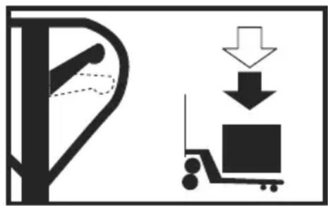
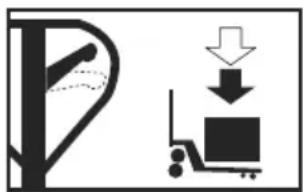
Diagram showing a forklift and a cargo cart with downward arrows indicating loading or movement (no text or symbols)LOWER
natural_image
Symbolic illustration of a person walking next to a computer monitor with an arrow indicating direction (no text or symbols present)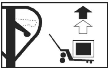
natural_image
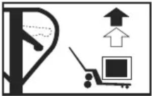
Diagram showing a parking lot with an upward arrow and a cart with an open square (no text or symbols)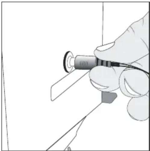
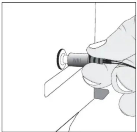
natural_image
Illustration of a hand holding a pen or tool with a circular component, no text or symbols visibleCONTROL LEVER
The control lever (H106) can be set in three positions (see below).
natural_image
Diagram showing a tree with a hand holding a leaf and a box being lifted by a pulley (no text or symbols)LOWER:
Push lever up to lower
the forks
text_image
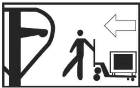
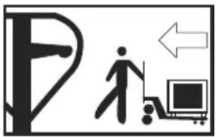
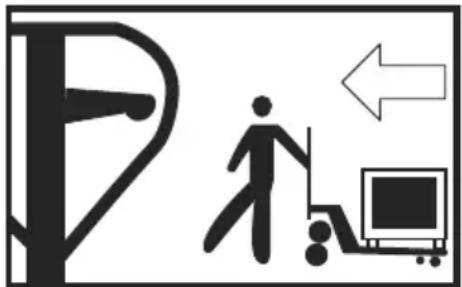
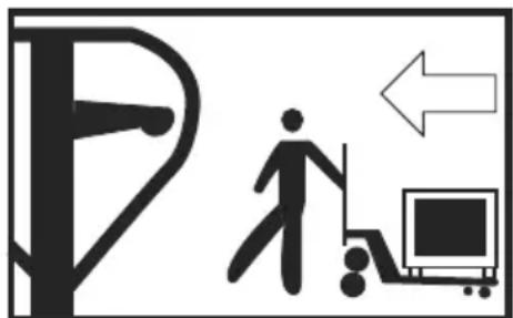
Traffic sign indicating a pedestrian crossing with a person walking, a computer monitor, and an arrow pointing left.NEUTRAL:
to move the load
natural_image
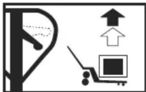
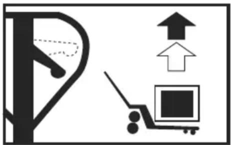
Simple line drawing of a parking lot with an upward arrow and a parking cart (no text or symbols)ASCENT:
Push lever down and pump handle to raise the forks.
ZEROING THE DISPLAY
You can press the ZERO key at any time to zero the scale. This will usually only be necessary when the pallet is empty. When the zero point is obtained the display will show zero.
The scale has an automatic rezeroing function to account for minor drifting or accumulation of material on the pallet. However, you may need to press the ZERO key to rezero the scale if small amounts of weight are shown when the pallet is empty.
TARING
Zero the scale by pressing the ZERO key if necessary. The zero indicator will be on.
Place a container on the pallet, display shows weight.
Press the TARE key to tare the scale. The weight that was displayed is stored as the tare value and that value is subtracted from the display. Zero shows on display.
The "GROSS" indicator will be off and "NET" indicator on. As product is added, only the weight of the product will be shown. The scale could be tared a second time if another type of product was to be added to the first one. Again only the weight that is added after taring will be displayed.
When the container is removed a negative value will be shown. If the scale was tared just before removing the container this value is the gross weight of the container plus all product that was removed. The zero indicator will be on because the pallet is back to the same condition it was when the ZERO key was last pressed. Press TARE key again to escape "NET" mode.
WEIGHING
Put the control lever in the LOWER position and lower the truck to lowest position.
Press the ON/OFF key to turn the scale on. After the indicator counts down, the display will zero. Place the forks under the pallet. While balancing load as evenly as possible, put lever in "Ascent" position and pump handle to raise load. Once stable indicator shows, the accurate weight of the load is displayed. (Total weight of pallet and the goods)
NET/GROSS FUNCTION
This function is only available after TARE function has been used. Pressing the N/G button will toggle between total weight (gross) on skid and weight after TARE function was used (NET).
SELECTING WEIGHING UNITS
Press U key to select desired weighing units (LBS or KG).
OPERATION CONTINUED
ACCUMULATION

NOTE: Before using Accumulation function, remove all weight from forks and zero the scale.
- Weigh item on scale. Once "stable" indicator shows, press M+ key to store weight in memory.
- The display will show "AC 01" and then the total in memory for 2 seconds before returning to normal.
- The M+ indicator is on. Remove the weight, allow the scale to return to zero, and put a second weight on the scale.
- Press M+ key, the display shows "AC 02" and then the new total.
- Continue until all weights have been added. The scale can accumulate up to 99 items.

NOTE: Changing weighing units during Accumulation Function will clear memory.
MEMORY RECALL
To view the totals in memory, press the M+ key while display reads zero, and display will show "AC n" ('n' is current accumulation times) and then the total in memory for 2 seconds. The scale then returns to normal.
TO CLEAR MEMORY
To clear the accumulated data in memory, press G/N key when total weight value is displayed.
PRETARE
- To set press and hold PT key for 3 seconds to display current tare value.
- Display now shows "Pts 0". Press TARE key to select desired prepare item. (0-9 preset items are available)
- After Pretare value has been entered, press ZERO key.
- To manually key in a tare value, use TARE key to select value and M+/PT keys to toggle between active digits.
- Once prepare item is selected, press ZERO key to store prepare value in memory.

NOTE: Pretare value is displayed while NET indicator is shown on display.
- Press U key to go back to normal weighing mode.
SELECT PRETARE
- Press G/N key to ensure scale is in net mode.
- Press PT key. "Ptl 0" is shown on display. Press TARE key to select desired stored item (0-9). Press ZERO key to display prepare value.
CLEAR PRETARE VALUE
- Press PT. Display will show "Ptl 0".
- Use TARE key to select desired prepare item (0-9).
- Press ZERO key to display prepare weight.
- Press and hold PT for 3 seconds and follow steps in section I to set prepare value to zero.
- Press U key to go back to normal weighing mode.
PARAMETERS (FUNCTION SETTING)
The scale has parameters that can be set by the user.
- To set parameters, press the ZERO key and TARE key at the same time.
- The display will show the first function, "F1 unit".
-
Pressing the TARE key will cycle through the other functions.
-
Pressing ZERO key will allow you to set the function.
-
It may be necessary to either use TARE key set a value or using the M+ and PT key to move the active digit and then using the TARE key to increment a digit, followed by the ZERO key to enter the value.
-
Use the U key to leave a parameter unchanged.
-
For example when the display shows "F1 unit" press the ZERO key to begin.
The display will show "ON Ib". Press the TARE key to set the weighing unit to ON/OFF status.
- Press ZERO key to enter value, and the scale will show the next weighing unit. Use TARE key to set and ZERO key to enter. When finished press U key to exit.
OPERATION CONTINUED
FUNCTION SETTING TABLE
| FUNCTION | SUB-FUNCTION DESCRIPTION DEFAULT VALUE | ||
| F1 u nt KG | Sets the displayed weight unit. Select kg ON/OFF | lb | |
| F3 off Bk Set | the backlight. | On: Always on.Auto: Press a key and weight is more than 20d,backlight comes on automatically.Off: Always off. | Auto |
| Off Set auto power off.OF 0: Don't use auto power off function.OF 3: Auto power off after standby 3 minutes.OF 5: Auto power off after standby 5 minutes.OF 15: Auto power off after standby 15 minutes.OF 30: Auto power off after standby 30 minutes. | of 0 | ||
BATTERY LIFE
The weighing indicator is battery operated. The battery life is approximately 60 hours.
LOW BATTERY INDICATOR
When the battery needs charging the battery symbol on the display turns on. The battery should be charged. The scale will operate for about 30 minutes then automatically switch off to protect the battery.
CHARGING THE BATTERY
Plug in the AC adapter. Scale does not need to be turned on. Battery should be charged for 15 hours for full capacity.
BATTERY CHARGING STATUS
On the left side of display window, an LED indicates battery charging status. When the scale is plugged in the internal battery will charge. Colors in the LED window indicate battery status:
- Green – Battery is fully charged.
- Red – Battery needs recharging.
Over time, the battery may fail to hold a full charge and eventually will need replacing.

WARNING! Never use any damaged charger or battery. Do not short circuit the battery across the + and - terminals. Do not dispose of batteries in a fire or in household waste. Check local regulations for proper disposal.
BATTERY PERFORMANCE
Always use original batteries and AC adapter. Scale is not intended for use with non-original batteries and/or battery chargers.
• AC adapter rating is 12V.
- New batteries or batteries stored for long periods of time may require longer charging times.
- Keep battery at or near room temperature when charging.
- Do not expose batteries to temperatures below 14°F (-10°C) or above 113°F (45°C).
• Fully charge battery before first use.
- Batteries should be charged once a month at minimum to maintain performance.
- If battery fails to hold a full charge or If battery life becomes unacceptable, contact Uline Customer Service at 1-800-295-5510.
MAINTENANCE
DAILY CHECK AND MAINTENANCE
A daily check of the pallet truck can help prevent accidents. Give special attention to the wheels (127), the axles (109), the handle (H101), the forks and control lever (H106). The forks should be unloaded and lowered in the lowest position when the job is completed.
LUBRICATION
Use motor oil or grease to lubricate all moveable parts.
GENERAL MAINTENANCE
-
Please check the oil level every six months. The volume of oil is about 10.1 fl. oz.
-
Use the hydraulic type oil according to temperature scale below.
| Temperature Oil | |
| -5°C ~ +45°C L | -HM68 Hydraulic oil (equivalent to ISO VG68) |
| -15°C ~ -5°C L | -HM46 Hydraulic oil (equivalent to ISO VG46) |
EXPEL AIR FROM THE PUMP UNIT
Air may get into the hydraulics due to transportation or pump disturbances. It can prevent forks from elevating while pumping in ASCENT position. To expel air: Put the control lever (H106) to the LOWER position, then move the handle (H101) up and down several times.
CALIBRATION
CALIBRATION WHEN THE SEAL IS NOT APPLIED
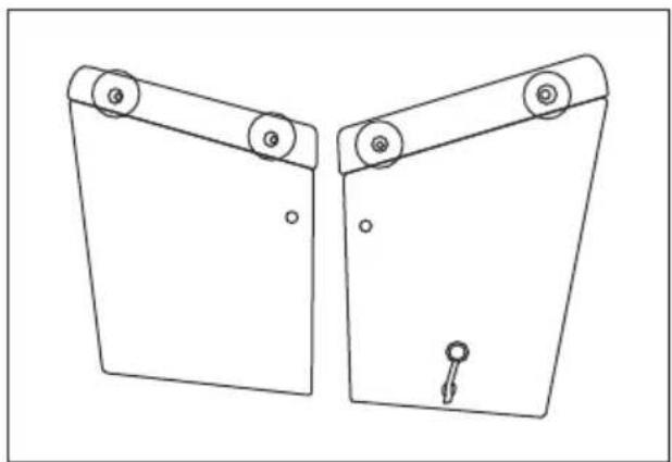
- Remove the assembly screws. The screws are located around the perimeter of the indicator top cover. Remove the four screws using the screwdriver.
natural_image
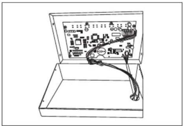
Technical line drawing of two mechanical components with rollers and a key (no text or symbols)- Open the top cover. The main board is mounted inside the top cover assembly.
natural_image
Line drawing of an open circuit board with visible traces and components (no text or symbols)- Power on the scale. Press the ON/OFF key to turn the scale on.
ENTER TECHNICAL PARAMETER MODE
NOTE: Must use 10% of capacity to calibrate.
- Press ZERO and TARE keys at the same time. The display shows "F1 UNIT".
CALIBRATION CONTINUED
- Press TARE key until display shows "PROG" and press ZERO key to show "PN" on the display.
- Press in order M+ , U and TARE keys to enter technical parameter setting mode.
| Prog P1 REF SPEED 7.5/15/30/60To set the AD speed. | 15 | ||
| P2 CAL DECI (0/0.0/0.00/0.000/0.0000/0.00000)To set the weighing decimal point. | |||
| INC (1/2/5/10/20/50/)To set the division. | |||
| CAPTo set the capacity. | |||
| CALTo calibrate the scale. | |||
| COUNTTo show the internal counts. | |||
| GRVTo set the local gravity. | |||
- Press TARE key to select parameter, press ZERO key to enter value and U key to exit.
- It may be necessary to use TARE key to set a value or use M+ and PT keys to move the active digit.
CALIBRATION
- Enter Technical Parameter Setting mode(see steps 1-3 above) until display shows "P1 rEF".
- Press the TARE key until display shows "P2 CAL". Press ZERO key to enter and press TARE key until display shows "CAL".
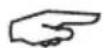
NOTE: Press the calibration switch (K3) on the main board to enable the calibration mode.
text_image
Calibration Switch (K K3- Press ZERO key to enter and press TARE key until display shows "CAL".
- Press ZERO key twice and display shows "UNLD". Remove all weight from the forks. After STABLE indicator is visible, press the ZERO key.
- The display shows the calibration weight value. Use the M^+ , PT and TARE keys to set the weight value.
NOTE: Use M+/PT keys to move active digit, use TARE key to change value. You can also press G/N to make value zero.
- After weight is keyed, press ZERO key to enter. Display will show "LOAD".
- Add calibration weight onto forks. After STABLE indicator is visible press ZERO key to enter.
- Display returns to normal once calibration is successful. If an error message is shown, try the calibration steps again; a disturbance may have prevented a successful calibration. If the problem persists, please contact Uline Customer Service.
CALIBRATION CONTINUED
CALIBRATION REQUIRING THE LEAD SEAL TO BE BROKEN
- Break the existing seal.

NOTE: Voids metrological verification. For authorized personnel only.
- Use diagonal cutters to cut the existing lead seal wire
- Carefully remove the broken seal wire from the holes in the screws.
-
Remove the lead seal screws from the indicator.
-
Calibration Operation. See steps under "Calibration When the Seal is Not Applied."
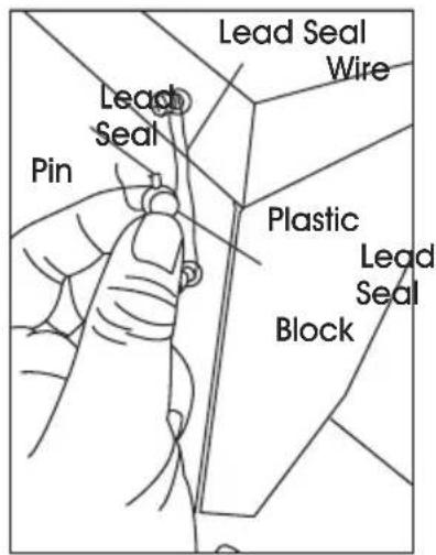
LEAD SEAL INSTALLATION GUIDE
COMPONENTS AND REQUIRED TOOLS
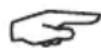
Components Included:
- Two Lead Seal Screws
- One Lead Seal Pin (Silver)
- One Plastic Lead Seal Block
- One Lead Seal Wire
Tools Needed:
- One Screwdriver
- One Pair of Pliers
text_image
Diagram showing labeled parts of a tool kit, including screwdriver, pliers, and a curved wire.LEAD SEAL INSTALLATION GUIDE CONTINUED
INSTALLATION STEPS
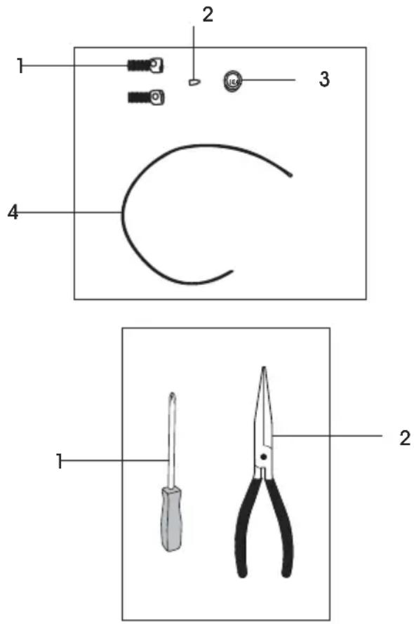
- Replace the assembly screws.
a. Locate the original assembly screws on the left side of the indicator.
b. Remove the original screws using a screwdriver.
c. Replace them with the provided lead seal screws and tighten them securely.
text_image
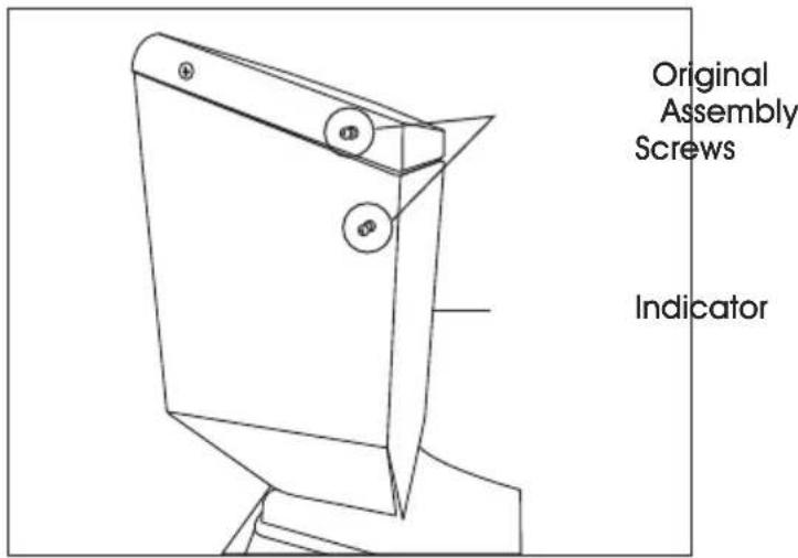
Original Assembly Screws Indicator- Thread and secure the lead seal wire.
a. Take the lead seal wire and thread it through the heads of both installed lead seal screws.
b. Bring the two remaining ends of the wire together and twist them into spiral to secure the loop.
text_image
Lead Seal Screws Lead Seal Wire- Pass the wire through the seal block.
a. Take the plastic lead seal block.
b. Pass the twisted ends of the wire through the two circular holes in the seal block.
c. Take the silver lead seal pin.
d. Insert it firmly into the square hole on the plastic lead seal block.
text_image
Lead Seal Wire Lead Seal Plastic Lead Seal Block- Lock the seal with the pin.
a. Use the pliers to squeeze and clamp the pin securely until it is flush and tight.
b. This action permanently locks the seal.
natural_image
Technical line drawing of a mechanical component with mounting holes and a handle (no text or symbols)PARTS DIAGRAM
DIAG 1
text_image
H110 H109 H107 103 109 139H 140 122HDIAG 2
text_image
LOWER position NEUTRAL position ASCENT position H106 H101DIAG 3
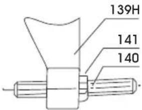
text_image
139H 141 140| PART NO. | PART NAME QTY. | |
| H107 Wire, Chain and Pin 1 | ||
| H109 Hex Screw 6 | ||
| H110 Spring Washer 6 | ||
| 122H Pump Housing 6 | ||
| 139H Crank Link 1 | ||
| 103 Base | 1 | |
| 109 Axle | 1 | |
| 140 | Set Screw | 1 |
| 141 | Nut | 1 |
| H101 Handle | 1 | |
| H106 Control Lever | 1 | |
PARTS DIAGRAM CONTINUED
text_image
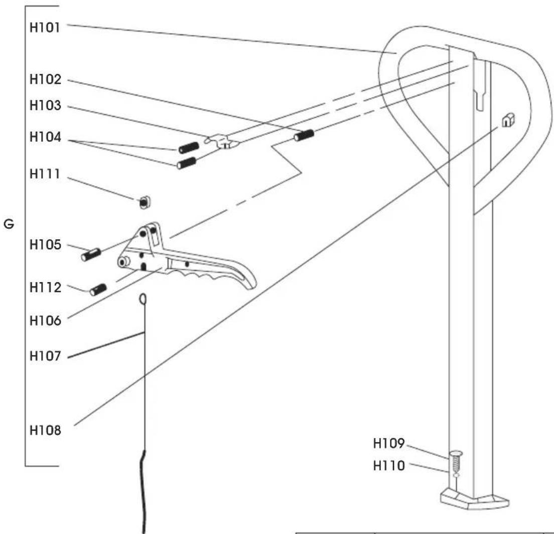
H101 H102 H103 H104 H111 G H105 H112 H106 H107 H108 H109 H110| PART NO. | PART NAME QTY. | |
| H101 Handle 1 | ||
| H102 Spring Pin 1 | ||
| H103 Spring Leaf 1 | ||
| H104 Spring Pin 2 | ||
| H105 Spring Pin 1 | ||
| H106 Control Lever 1 | ||
| H107 Wire, Chain and Pin 1 | ||
| H108 Rubber Cushion 1 | ||
| H109 Hex Screw 6 | ||
| H110 | Spring Washer | 6 |
| H111 | Nylon Roller | 1 |
| H112 | Spring Pin 1 | |
PARTS DIAGRAM CONTINUED
text_image
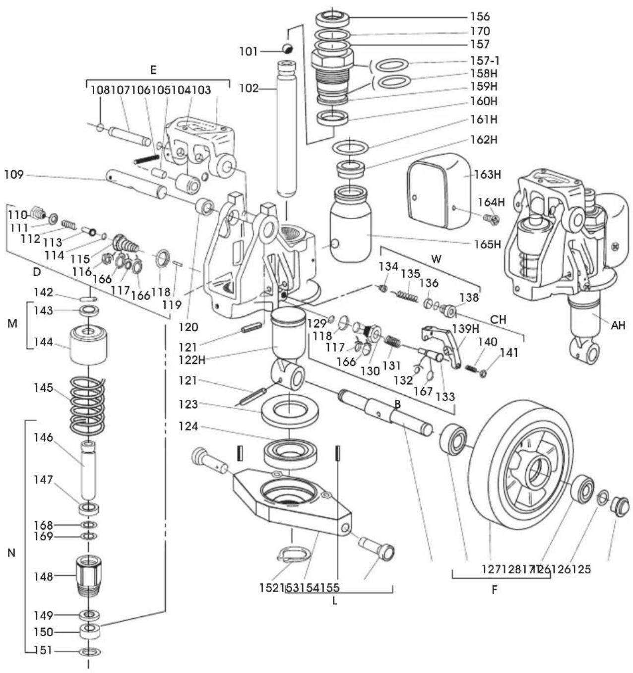
Exploded view diagram of a mechanical assembly with numbered parts and Chinese labelsPARTS LIST
| PART NO. | PART NAME QTY. | |
| 101 Steel | Ball 1 | |
| 102 Rod 1 | ||
| 103 Base 1 | ||
| 104 Steel | Roller 1 | |
| 105 Bushing 1 | ||
| 106 Pin 1 | ||
| 107 Shaft 2 | ||
| 108 Retaining Ring 1 | ||
| 109 Axle | 1 | |
| 110 | Screw | 1 |
| 111 | Washer | 1 |
| 112 | Spring | 1 |
| 113 | Pressure Rod | 1 |
| 114 | Steel Ball 1 | |
| 115 | Pressure Valve Body | 1 |
| 116 | Split Ring | 1 |
| 117 | O-Ring | 2 |
| 118 | Washer | 2 |
| 119 | Steel Needle | 1 |
| 120 Bushing 2 | ||
| 121 | Pin 1 | |
| 122H | Pump Body | 1 |
| 123 Dust Cover | 1 | |
| 124 Bearing 1 | ||
| 125 Steering Wheel Axle | 1 | |
| 126 Bearing 4 | ||
| 127 | Steering Wheel | 2 |
| 128 Retaining Ring 2 | ||
| 129 Steel Ball 1 | ||
| 130 | Discharge Valve Body | 1 |
| 131 | Spring | 1 |
| 132 O-Ring | 1 | |
| 133 Discharge Valve Shaft | 1 | |
| 134 Valve Taper Core | 1 | |
| 135 Spring | 1 | |
| 136 Pressure Regulating O-Ring | 1 |
| PART NO. | PART NAME QTY. | |
| 138 Screw | 1 | |
| 139H | Crank Link | 1 |
| 140 Set Screw | 1 | |
| 141 | Nut | 1 |
| 142 | Parallel Pin | 1 |
| 143 | Retaining Cover | 1 |
| 144 | Spring Cover | 1 |
| 145 | Spring | 1 |
| 146 | Pump Rod | 1 |
| 147 | Dust Proof Ring 1 | |
| 148 | Pump Cylinder 1 | |
| 149 | Seal Ring | 1 |
| 150 Nylon Bushing | 1 | |
| 151 Red Copper Washer | 1 | |
| 152 Retaining Ring 1 | ||
| 153 Rhombus Plate 1 | ||
| 154 Pin 1 | ||
| 155 Dowel Pin | 2 | |
| 156 Dust Proof Ring | 2 | |
| 157 O-Ring | 1 | |
| 157-1 | O-Ring | 1 |
| 158H | O-Ring | 1 |
| 159H | Cylinder | 1 |
| 160H | Seal Ring | 1 |
| 161H | O-Ring | 1 |
| 162H | Filler Plug | 1 |
| 163H | Reservoir Cover | 1 |
| 164H | Screw | 1 |
| 165H | Reservoir | 2 |
| 166 Retainer | 1 | |
| 167 Retainer | 3 | |
| 168 Retainer | 1 | |
| 169 O-Ring | 1 | |
| 170 | Dust Cover | 1 |
| 171 | Bearing Cover | 2 |
ERROR CODES
| ERROR CODES | DESCRIPTION RESOLUTION | |
| --OL-- Overload | Remove weight from the scale. | If the problem persists, contact Uline Customer Service at 1-800-295-5510. |
| --UL-- | Under Load | Minus weight, check the platform and restart or calibrate. |
| Err 4 Zero Setting | Error The scale was outside | the normal zero settingrange either when it was turned on or when the ZERO key was pressed.Remove weight from the scale and try again.Use the TARE key to set the display to zero value.If the problem persists, contact Uline Customer Service at 1-800-295-5510. |
| Err 6 A/D out of range | The values from the A/D converter are outsidethe normal range. Remove weight from the scale if overloaded, make sure fork cover plate is attached.Indicates the load cell or the electronics may be faulty.If the problem persists, contact Uline Customer Service at 1-800-295-5510. | |
| Err 19 | Initialize Zero Error | Calibrate the scale. |
| fai I | Calibration Error | Check the test weights and recalibrate. |
| Ba lo | Battery Low | Recharge the battery, check the voltages. |
PATÍN HIDRÁULICO CON BÁSCULA
natural_image
Line drawing of a manual pallet jack with control panel and wheels (no text or symbols)INFORMACIÓN GENERAL
natural_image
Diagram showing a crane lifting a box with a downward arrow, next to a forklift (no text or symbols)LOWER (bajar)
text_image
Diagram showing a person walking next to a computer with an arrow indicating direction, alongside a vertical pole symbol.NEUTRAL (neutro)
text_image
Diagram showing a parking lot with directional arrows and a parking cart, indicating parking or parking movement.ASCENT (elevar)
natural_image
Hand holding a medical or surgical tool with a needle inserted, no visible text or symbolsPALANCA DE CONTROL
natural_image
Simple line drawing of a tree with a downward arrow and a small box, no text or symbols present.text_image
Diagram showing a person walking with a computer monitor and directional arrow, likely indicating a transportation or safety concept.NEUTRAL (neutro): para mover la carga
text_image
Diagram showing a vehicle and a parking lot with upward arrows indicating movement or change, alongside a parking cart.natural_image
Technical line drawing of two mechanical components with rollers and a key (no text or symbols)natural_image
Line drawing of an open circuit board with exposed wiring and components, no text or symbols presentnatural_image
Technical line drawing of a mechanical component with mounting holes and a lever mechanism (no text or symbols)DIAGRAMA DE PARTES
DIAG 1
text_image
H110H109 H107 103 109 139H 140 122HDIAG 2
text_image
Exploded view diagram of a mechanical assembly with numbered parts and labeled sections (A-H)LISTA DE PARTES
natural_image
Line drawing of a manual pallet jack with control panel and wheels (no text or symbols)RENSEIGNEMENTS GÉNÉRAUX
ÉVITEZ DE PLACER LA BALANCE DANS DES ENDROITS OÙ SA PRÉCISION PEUT ÊTRE COMPROMISE :
| CARACTÈRE AFFICHAGE | |
| I | 1 |
| J | J |
| K | F |
| L | L |
| M | n |
| N | n |
| O | o |
| P | P |
| Q | o |
| R | r |
| S | 5 |
| T | t |
| U | U |
| V | u |
| W | u |
| X | = |
| Y | y |
| Z | 2 |
COMMANDES

Fonction principale

Fonction secondaire

natural_image
Diagram of a human foot pressing down on a mechanical device, showing hand positioning and motion path (no text or symbols)II. FIXEZ LE PANNEAU DE COMMANDE
natural_image
Technical diagram showing mechanical assembly with no visible text or symbolsnatural_image
Illustration of hands using a screwdriver to adjust or install a device (no text or symbols visible)natural_image
Technical line drawing of a mechanical assembly with labeled component 'Figure 4' (no readable text or symbols beyond label)natural_image
Diagram showing a crane lifting a box with a downward arrow, next to a forklift (no text or symbols)LOWER (DARKENDRE)
natural_image
Symbolic illustration of a person walking next to a computer monitor with an arrow indicating direction (no text or symbols present)NEUTRAL (NEUTRE)

natural_image
Diagram showing a parking lot with an upward arrow and a parking cart with an open square (no text or symbols)ASCENT (MONTER)
natural_image
Hand holding a pen or tool with a circular component, no visible text or symbolsFONCTIONNEMENT
LEVIER DE COMMANDE
text_image
Diagram showing a tree with a downward arrow and a box, likely indicating a process or system step.text_image
Diagram showing a person walking with a computer and directional arrow, possibly indicating movement or accessibility.natural_image
Simple line drawing of a tree with an upward arrow and a computer monitor (no text or symbols)natural_image
Line drawing of two mechanical components with rollers and a key (no text or symbols)natural_image
Line drawing of an open circuit board with exposed components and wires, no text or symbols presentnatural_image
Technical line drawing of a mechanical component with mounting holes and a lever (no text or symbols)SCHÉMA DES PIÈCES
SCHÉMA 1
text_image
H110H109 H107 103 109 139H 140 122HSCHÉMA 2