
H-11973 - Door closer Uline - Free user manual and instructions
Find the device manual for free H-11973 Uline in PDF.

User questions about H-11973 Uline
0 question about this device. Answer the ones you know or ask your own.
Ask a new question about this device
Download the instructions for your Door closer in PDF format for free! Find your manual H-11973 - Uline and take your electronic device back in hand. On this page are published all the documents necessary for the use of your device. H-11973 by Uline.
USER MANUAL H-11973 Uline
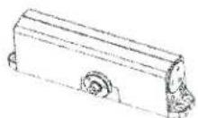
natural_image
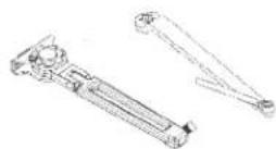
Technical line drawing of a mechanical linkage assembly (no text or symbols)TOOLS NEEDED
Tape Measure
Adjustable Wrench
Phillips
Screwdriver

PunchPencil
Safety Glasses

Drill

7 and 1/4-20
Drill Bits (for metal)

3/16" Drill Bit (for wood)

9/32" and 3/8"
Drill Bits
(nut and bolt option)

1/8" Hex Wrench (included)
PARTS
Closer x 1

Pinion Cap x 1
Arm Assembly x 1

Main Arm Pinion Screw x 1 Parallel Arm Bracket x 1 1/4-14 x 1 ^1/2 "
Oval Flat Head Self-Drilling Screw x 8 (for wood/metal frames)

1/4-20 x 3/4"
Oval Flat Head Machine Screw x 8
(for metal frames)

1/4-20 x 1/2"
Round Head Machine Screw x 2
(for all frames)
1/4-14 x 1 1/4"
Round Head Self-Drilling Screw x 2
(for wood/metal frames)
SAFETY

CAUTION! An incorrectly installed or improperly adjusted door closer can cause property damage or personal injury. These installation instructions should be followed to avoid the possibility of misapplication or improper adjustment.
- Doors should be hung on ball bearing or anti-friction hinges.
• A separate doorstop is recommended.
• Always consult door/frame manufacturer for fastener compatibility.
• Door and frame must be properly reinforced.
- Adjust closing time speed between 3 and 7 seconds from 90^ to 0^ .
- These door closers should not be installed on exposed side (weather side) of exterior doors.
INSTALLATION
PULL SIDE MOUNTING

NOTE: Right-hand installation is shown.
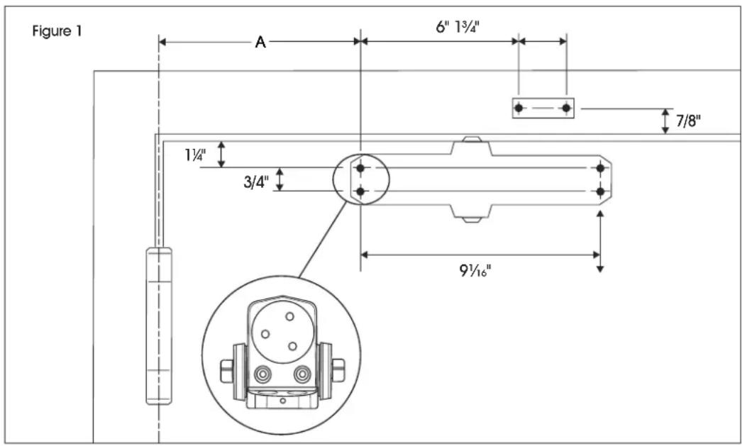
- Mark holes at indicated locations on door and frame. (See Figure 1)
| OPENING DIMENSION A | |
| To 100^ 7" | |
| 101^ - 120^ 6" | |
| * 121^ - 180^ 3 12 " | |
*Door/wall/hardware/jamb conditions permitting.
text_image
Figure 1 A 6" 1¾" 7/8" 1¾" 3/4" 9½"INSTALLATION CONTINUED
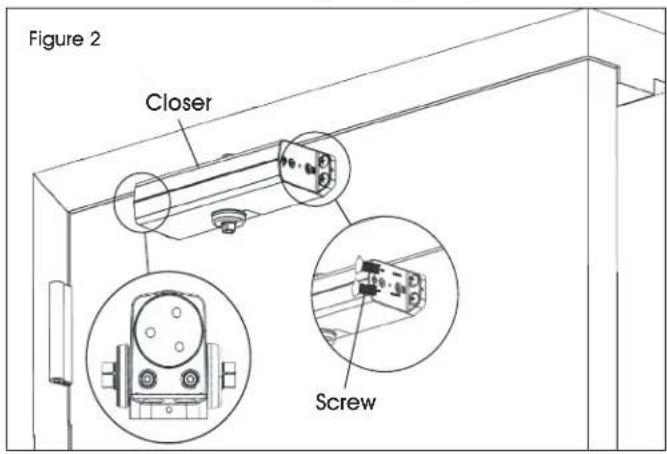
- Mount closer to door using four 1/4-14 x 1½" oval flat head self-drilling screws or 1/4-20 x 3/4" oval flat head machine screws. (See Figure 2)
text_image
Figure 2 Closer Screw
NOTE: See "Tools Needed" on page 1 for proper installation hardware.
- Remove dial from hold-open arm and install separate arms using four 1/4-14 x 1½" oval flat head self-drilling screws or 1/4-20 x 3/4" oval flat head machine screws. (See Figure 3)

text_image
Figure 3 Main Arm Pinion Screw Flat Dial Screw
CAUTION! Dial should face down for left- and right-hand installations.

NOTE: For left- and right-hand installations, position pinion with flat at point S.
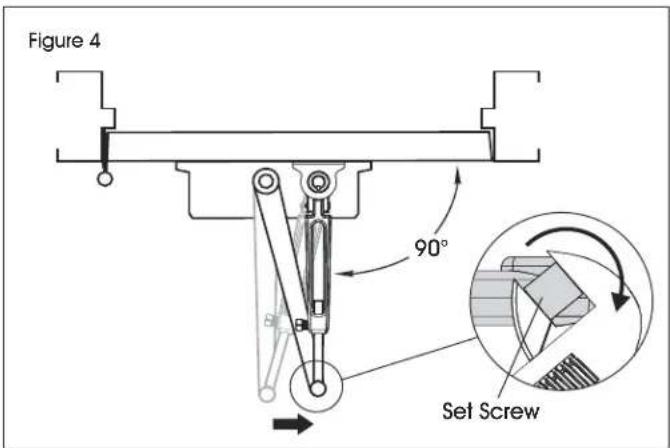
- Connect arms, preload spring and tighten set screw. (See Figure 4)

IMPORTANT! Rotating arm preloads closer spring power. Rotate elbow until hold-open arm is perpendicular to frame.
text_image
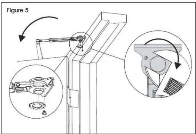
Figure 4 90° Set Screw- Set hold open, then replace dial. (See Figure 5)

NOTE: Keep door open in position until dial screw secures dial.
text_image
Figure 5- Installation is complete. Proceed to page 9 for closer adjustments and decorative cap installation.
INSTALLATION CONTINUED
TOP JAMB MOUNTING

NOTE: Right-hand installation is shown.
- Mark holes at indicated locations on door and frame. (See Figure 6)
| OPENING DIMENSION A | |
| To 100^ 712'' | |
| 101^ – 120^ 6'' | |
| * 121^ – 180^ 312'' | |
*Door/wall/hardware/jamb conditions permitting.
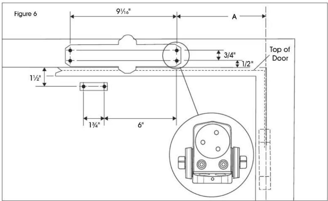
text_image
Figure 6 9½" A 3/4" 1/2" Top of Door 1½" 1¾" 6"- Mount closer to door using four 1/4-14 x 1½" oval flat head self-drilling screws or oval flat head machine screws. (See Figure 7)
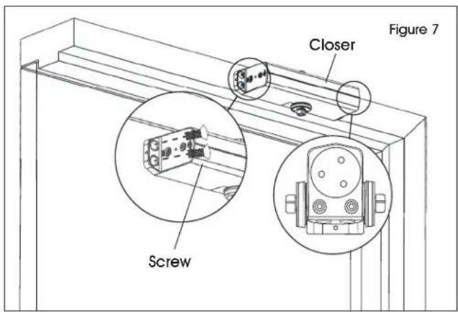
text_image
Figure 7 Closer Screw
NOTE: See "Tools Needed" on page 1 for proper installation hardware.
- Remove dial from hold-open arm and install separate arms using two 1/4-20 x 3/4" oval flat head machine screws. (See Figure 8)
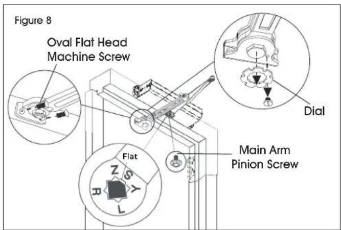
text_image
Figure 8 Oval Flat Head Machine Screw Dial Flat Main Arm Pinion Screw
CAUTION! Dial should face down for left- and right-hand installations.

NOTE: For left- and right-hand installations, position pinion with flat at point S.
INSTALLATION CONTINUED
- Connect arms, preload spring and tighten set screw. (See Figure 9)

IMPORTANT! Rotating arm preloads closer spring power. Rotate elbow until hold-open arm is perpendicular to frame.
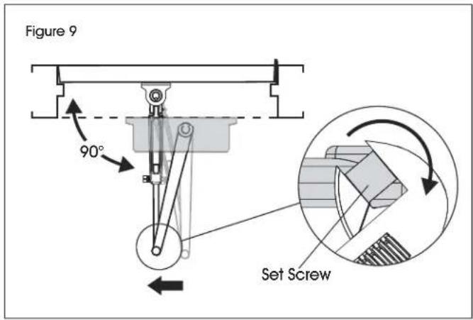
text_image
Figure 9 90° Set Screw- Set hold open, then replace dial. (See Figure 10)

NOTE: Keep door open in position until dial screw secures dial. (See Figure 10)
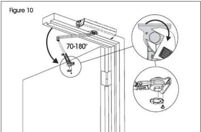
text_image
Figure 10 70-180°- Installation is complete. Proceed to page 9 for closer adjustments and decorative cap installation.
INSTALLATION CONTINUED
PARALLEL ARM MOUNTING

NOTE: Right-hand installation is shown.
- Mark holes at indicated locations on door and frame. (See Figure 11)
| OPENING DIMENSION A DIMENSION B | |
| To 100°91⁄4"75⁄8" | |
| 101°-130°73⁄4"61⁄8" | |
| *131°-180°53⁄4"41⁄8" | |
*Door/wall/hardware/jamb conditions permitting.
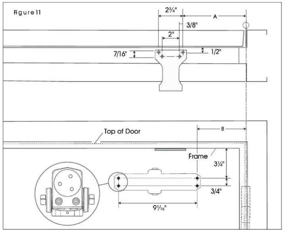
text_image
Figure 11 2¾" 3/8" 2" 7/16" 1/2" Top of Door Frame 3½" 3/4" 9½"- Close latch and sweep valves using included hex wrench. (See Figure 12)

natural_image
Technical line drawing of a mechanical device with a lever and adjustment knob (no text or symbols)- Remove dial from hold-open arm. (See Figure 13)
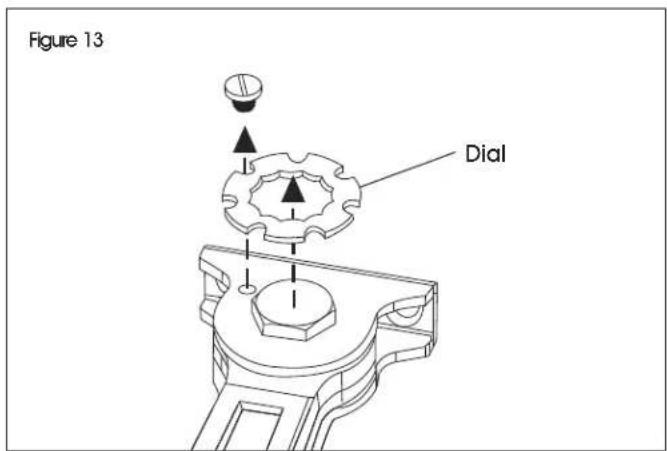
text_image
Figure 13 DialINSTALLATION CONTINUED
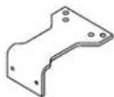
- Install parallel arm bracket and mount closer using eight 1/4-14 x 1½" oval flat head self-drilling screws or 1/4-20 x 3/4" oval flat head machine screws. (See Figure 14)

NOTE: See "Tools Needed" on page 1 for proper installation hardware.
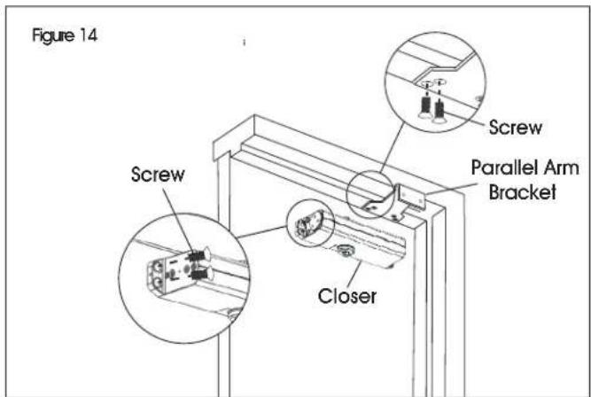
text_image
Figure 14 Screw Screw Closer Parallel Arm Bracket- Install hold-open arm to bracket using two 1/4-20 x 1/2" round head machine screws. (See Figure 15)

CAUTION! Dial should face down for left- and right-hand installations.
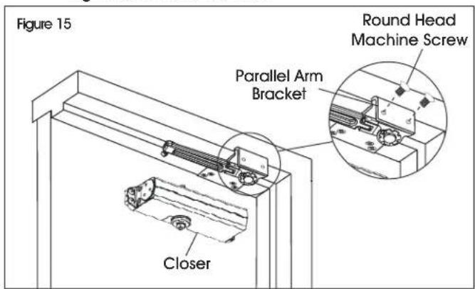
text_image
Figure 15 Round Head Machine Screw Parallel Arm Bracket Closer- Place main arm on closer spindle and rotate. (See Figure 16)
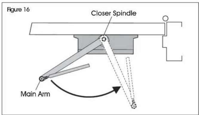
text_image
Figure 16 Closer Spindle Main Arm- Remove arm and attach as shown. (See Figure 17)

NOTE: For right-hand installation, position flat at point R. For left-hand installation, position flat at point L.
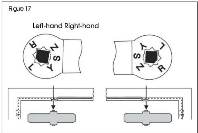
text_image
Figure 17 Left-hand Right-hand- Open latch and sweep valves using included hex wrench. (See Figure 18)

NOTE: Do not completely open valves. Valves will leak.

CAUTION! Arm under tension. Keep fingers away from moving parts.
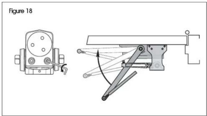
text_image
Figure 18INSTALLATION CONTINUED
- Connect arms, preload spring and tighten set screw. (See Figure 19)

NOTE: Rotating arm preloads closer spring power. By hand, rotate arm eblow to be 1½" from door face.
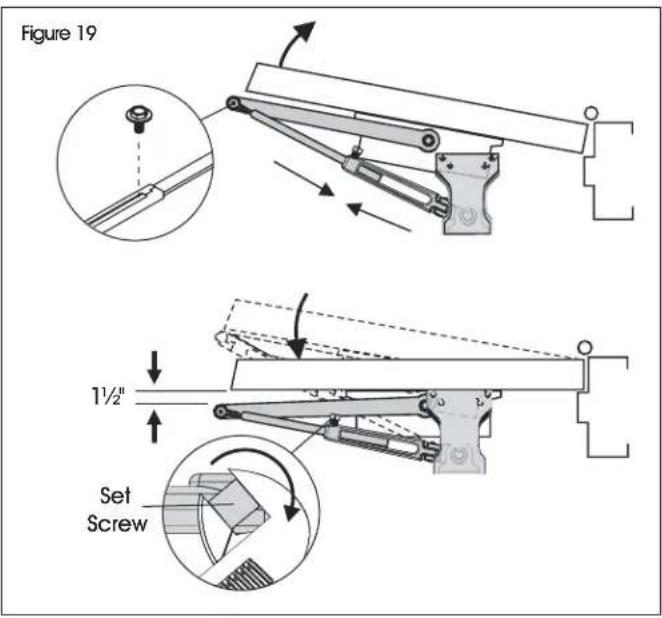
text_image
Figure 19 1½" Set Screw- Set hold open, then replace dial. (See Figure 20)

NOTE: Keep door open in position until dial screw secures dial.

NOTE: For right-hand installation, turn clockwise to tighten. For left-hand installation, turn counterclockwise to tighten.
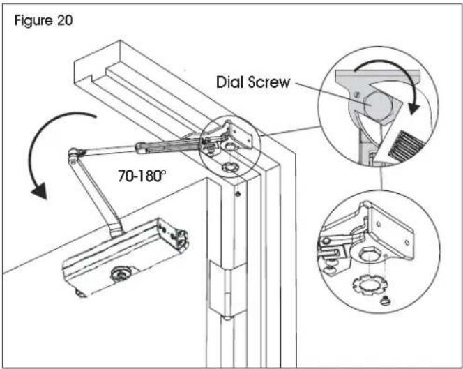
text_image
Figure 20 Dial Screw 70-180°- Installation is complete. Proceed to page 9 for closer adjustments and decorative cap installation.
INSTALLATION CONTINUED
CLOSER ADJUSTMENTS

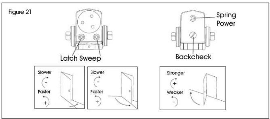
CAUTION! Use provided hex wrench to turn valves. Never force valves out of closer. Never completely close backcheck valve. (See Figure 21)

NOTE: Door must be open to adjust spring closing power. Refer to chart. Do not use a power drill. Warranty will be void. (See Figure 21)
text_image
Figure 21 Latch Sweep Spring Power Backcheck Slower - Faster + Slower - Faster + Stronger + Weaker| SPRING CLOSING POWER | NUMBER OF TURNS REQUIRED*(ships pre-loaded with 8 turns) | |||||
| DOOR | TYPE OF INSTALLATION | Maximum Door Size | ||||
| 34" | 36" | 40" | 44" | 48" | ||
| Interior | Regular Arm Top Jamb | 2 4 6 | 10 12 | |||
| Parallel Arm | 3 | 5 | 8 | 11 | 14 | |
| Exterior | Regular Arm Top Jamb | 3 | 5 | 8 | 11 | 14 |
| Parallel Arm | 5 | 8 | 11 | 16 | 19 | |
*30 full (360°) turns maximum available.
PINION CAP INSTALLATION

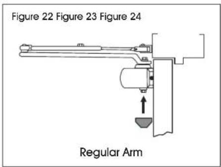
NOTE: Do not over-tighten cap or cover screws. (See Figures 22-24)
text_image
Figure 22 Figure 23 Figure 24 Regular Arm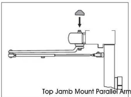
text_image
Top Jamb Mount Parallel Arm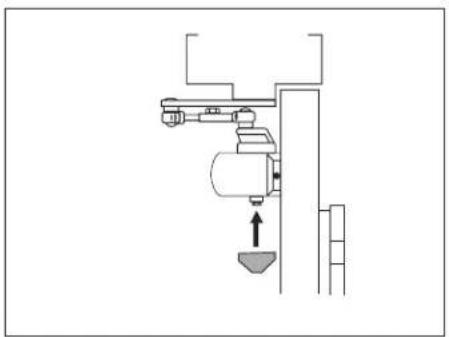
natural_image
Pure mechanical assembly diagram without any text, numbers, or symbols
natural_image
Technical line drawing of a mechanical hinge or latch assembly (no text or symbols)natural_image
Technical line drawing of a mechanical assembly with no visible text or symbols
H-11973
NORTON ^MD – FERME-PORTE
À USAGE MOYENS AVEC RÉTENTION
1 800 295-5510
uline.ca


