
H-11970 - Door closer Uline - Free user manual and instructions
Find the device manual for free H-11970 Uline in PDF.

User questions about H-11970 Uline
0 question about this device. Answer the ones you know or ask your own.
Ask a new question about this device
Download the instructions for your Door closer in PDF format for free! Find your manual H-11970 - Uline and take your electronic device back in hand. On this page are published all the documents necessary for the use of your device. H-11970 by Uline.
USER MANUAL H-11970 Uline
natural_image
Technical line drawing of a mechanical clamp or bracket assembly (no text or symbols)TOOLS NEEDED
Tape Measure

Adjustable Wrench
Phillips
Screwdriver

PunchPencil
Safety Glasses

Drill

7 and 1/4-20
Drill Bits (for metal)

3/16" Drill Bit (for wood)

9/32" and 3/8"
Drill Bits
(nut and bolt option)

1/8" Hex Wrench (included)
PARTS
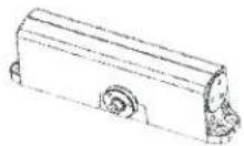
Closer x 1

Pinion Cap x 1
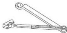
Arm Assembly x 1

Main Arm
Pinion Screw x 1
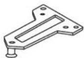
Parallel Arm Bracket x 1
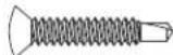
1/4-14 x 1½"
Oval Flat Head Self-Drilling Screw x 4
(for wood/metal frames)
Sleeve Nut and Bolt x 4 (for wood/metal frames)

1/4-20 x 3/4"
Oval Flat Head Machine Screw x 4
(for metal frames)

1/4-20 x 5/8"
Round Head Machine Screw x 2
(for all frames)
1/4-14 x 1"
Round Head Self-Drilling Screw x 2
(for wood/metal frames)
SAFETY

CAUTION! An incorrectly installed or improperly adjusted door closer can cause property damage or personal injury. These installation instructions should be followed to avoid the possibility of misapplication or improper adjustment.
- Doors should be hung on ball bearing or anti-friction hinges.
• A separate doorstop is recommended.
• Always consult door/frame manufacturer for fastener compatibility.
• Door and frame must be properly reinforced.
- Adjust closing time speed between 3 and 7 seconds from 90^ to 0^ .
• These door closers should not be installed on exposed side (weather side) of exterior doors.
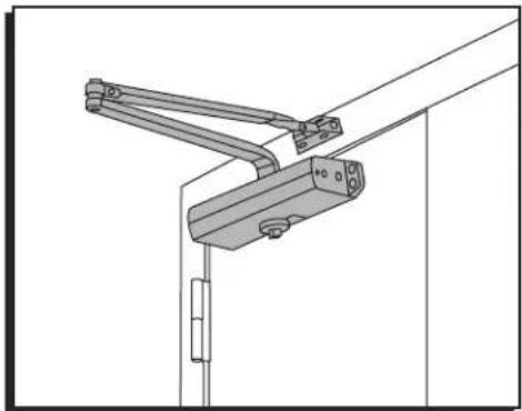
INSTALLATION
REGULAR ARM MOUNTING

NOTE: Right-hand installation is shown.
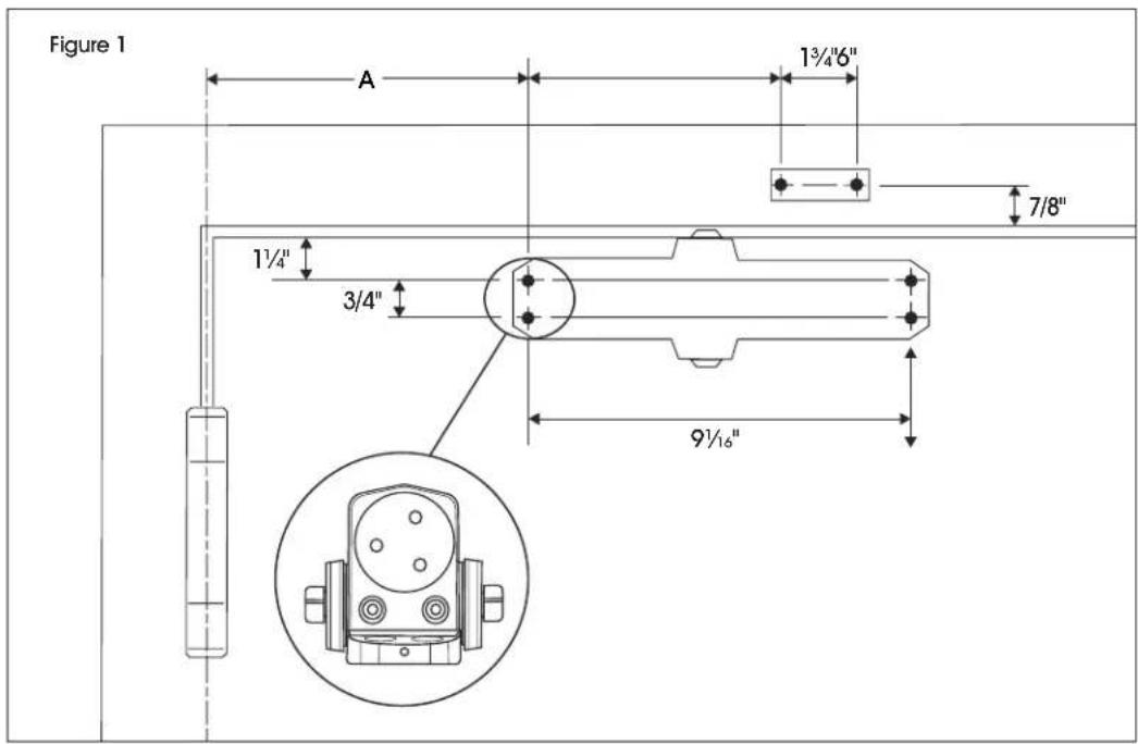
- Mark holes at indicated locations on door and frame. (See Figure 1)
| OPENING DIMENSION A | |
| To 100° 7" | |
| 101°-120° 6" | |
| *121°-180° 3 12 " | |
*Door/wall/hardware/jamb conditions permitting.
text_image
Figure 1 A 1¾"6" 7/8" 1¼" 3/4" 9½"INSTALLATION CONTINUED
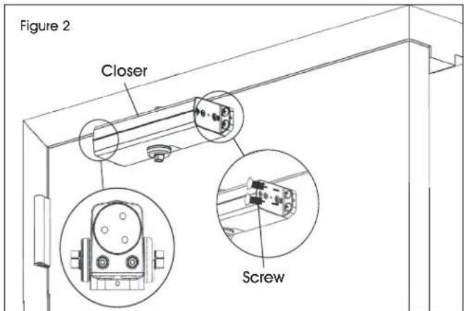
- Mount closer to door using four 1/4-14 x 1½" oval flat head self-drilling screws or oval flat head machine screws. (See Figure 2)
text_image
Figure 2 Closer Screw
NOTE: See "Tools Needed" on page 1 for proper installation hardware.
- Choose arm placement in shoe and install arms using two 1/4-14 x 1" round head self-drilling screws or 1/4-20 x 5/8" round head machine screws. (See Figures 3-4)
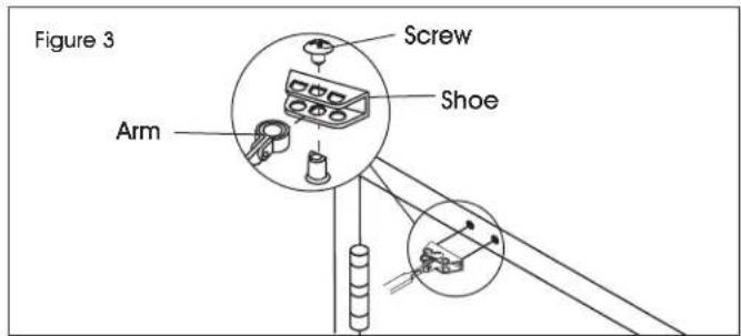
text_image
Figure 3 Arm Screw Shoe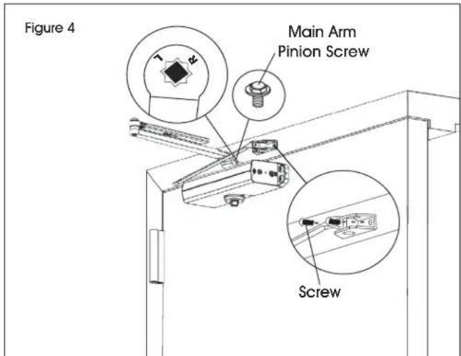
text_image
Figure 4 Main Arm Pinion Screw Screw- Connect arms and install forearm screw. (See Figure 5)
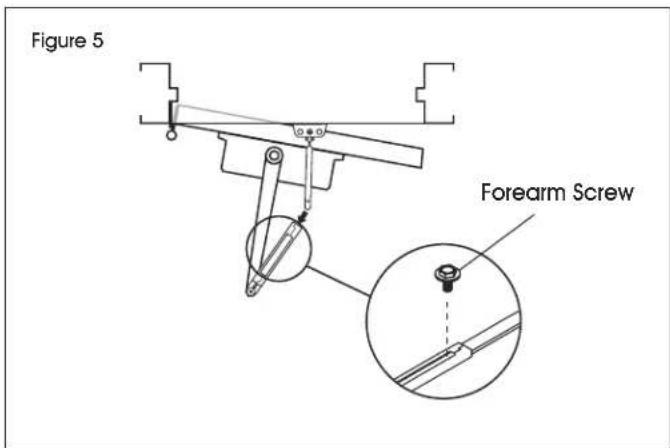
text_image
Figure 5 Forearm Screw- Preload spring and tighten forearm screw. (See Figure 6)

IMPORTANT! Rotating arm preloads closer spring power. Rotate elbow until connecting rod is perpendicular to frame.
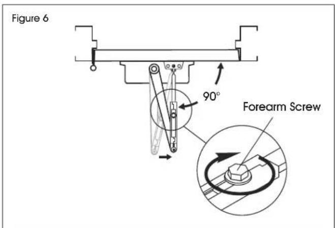
text_image
Figure 6 90° Forearm Screw- Installation is complete. Proceed to page 8 for closer adjustments and decorative cap installation.

NOTE: For left- and right-hand installations, position arm perpendicular to closer.
INSTALLATION CONTINUED
TOP JAMB MOUNTING

NOTE: Right-hand installation is shown.
- Mark holes at indicated locations on door and frame. (See Figure 7)
| OPENING DIMENSION A | |
| To 100° 7 12 " | |
| 101°-120° 6" | |
| *121°-180° 3 12 " | |
*Door/wall/hardware/jamb conditions permitting.
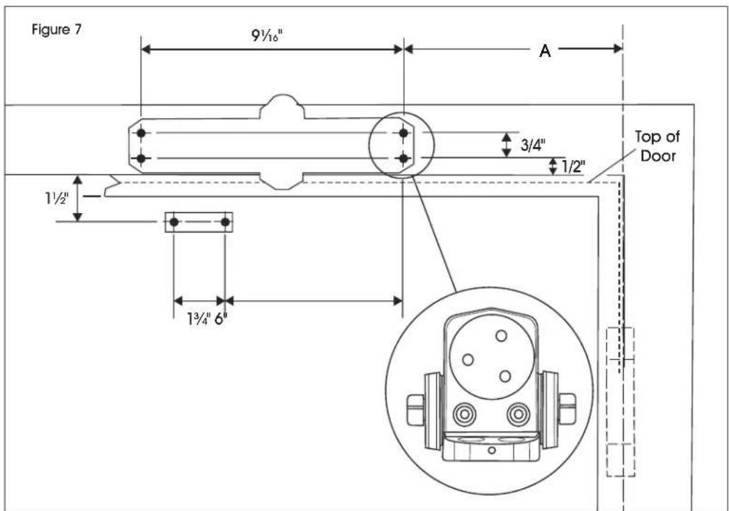
text_image
Figure 7 9½" A 3/4" 1/2" 1½" 1¾"6" Top of Door- Mount closer to frame using four 1/4-14 x 1½" oval flat head self-drilling screws or oval flat head machine screws. (See Figure 8)
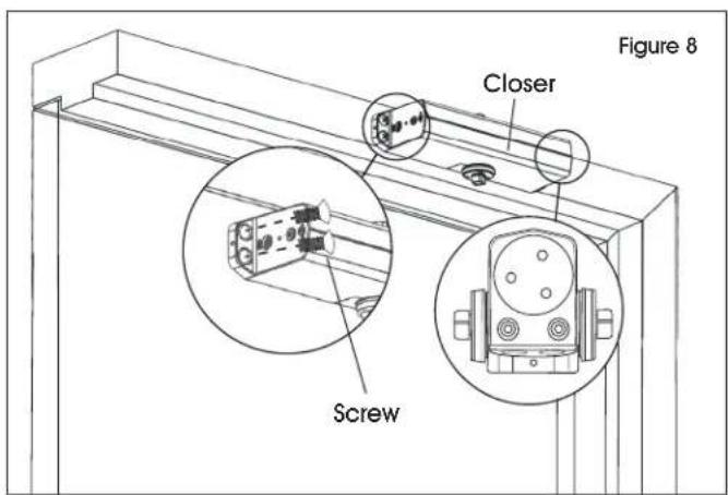
text_image
Figure 8 Closer Screw
NOTE: See "Tools Needed" on page 1 for proper installation hardware.
INSTALLATION CONTINUED
- Choose arm placement in shoe and install separate arms using two 1/4-14 x 1½" round head self-drilling screws or 1/4-20 x 5/8" round head machine screws. (See Figures 9-10)

text_image
Arm Shoe Figure 9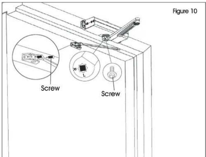
text_image
Figure 10 Screw Screw
NOTE: For left- and right-hand installations, position arm perpendicular to closer.
- Connect arms and install forearm screw. (See Figure 11)
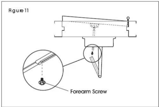
text_image
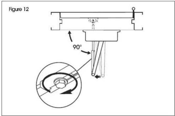
Figure 11 Forearm Screw- Preload spring and tighten forearm screw. (See Figure 12)

IMPORTANT! Rotating arm preloads closer spring power. Rotate elbow until connecting rod is perpendicular to frame.
text_image
Figure 12 90°- Installation is complete. Proceed to page 8 for closer adjustments and decorative cap installation.
INSTALLATION CONTINUED
PARALLEL ARM MOUNTING

NOTE: Right-hand installation is shown.
- Mark holes at indicated locations on door and frame. (See Figure 13)
| OPENING DIMENSION A DIMENSION B | |
| To 100° 9 14 ′′ 7 58 ′′ | |
| 101°–130° 7 34 ′′ 6 18 ′′ | |
| *131°–180° 5 34 ′′ 4 18 ′′ | |
*Door/wall/hardware/jamb conditions permitting.

text_image
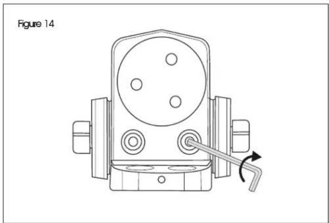
Figure 13 2¾" 3/8" 2" 7/16" 1/2" Top of Door Frame 3½" 3/4" 9½"- Close latch and sweep valves using included hex wrench. (See Figure 14)
natural_image
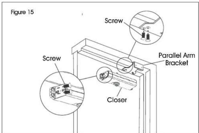
Technical line drawing of a mechanical device with a lever and adjustment knob (no text or symbols)- Install parallel arm bracket and mount closer using eight 1/4-14 x 1½" oval flat head self-drilling screws or 1/4-20 x 3/4" oval flat head machine screws. (See Figure 15)
text_image
Figure 15 Screw Screw Closer Parallel Arm Bracket
NOTE: See "Tools Needed" on page 1 for proper installation hardware.
INSTALLATION CONTINUED
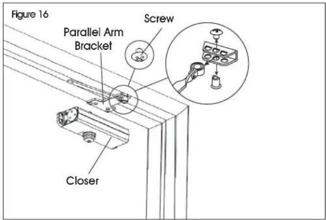
- Remove arm shoe and install forearm to bracket. (See Figure 16)
text_image
Figure 16 Parallel Arm Bracket Screw Closer- Place main arm on closer spindle and rotate. (See Figure 17)
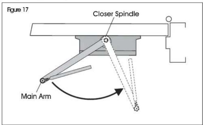
text_image
Figure 17 Closer Spindle Main Arm- Remove arm and attach as shown. (See Figure 18)
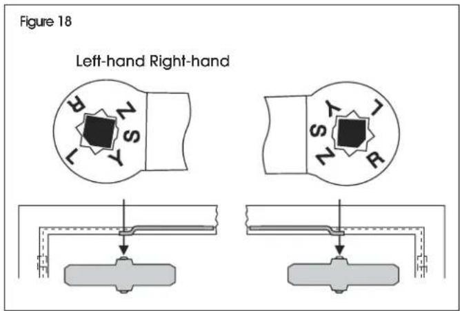
text_image
Figure 18 Left-hand Right-hand- Open latch and sweep valves using included hex wrench. (See Figure 19)

NOTE: Do not completely open valves. Valves will leak.

CAUTION! Arm under tension. Keep fingers away from moving parts.
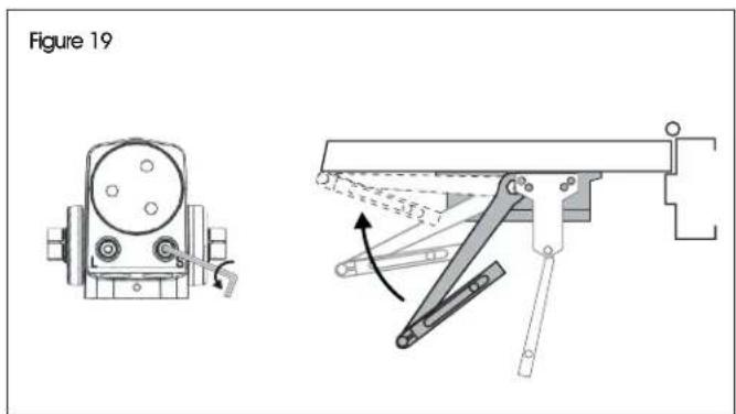
text_image
Figure 19- Connect arms and install forearm screw. (See Figure 20)
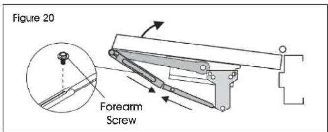
text_image
Figure 20 Forearm Screw- Preload spring and tighten forearm screw. (See Figure 21)

NOTE: Rotating arm preloads closer spring power. By hand, rotate arm elbow to be 1½" from door face.
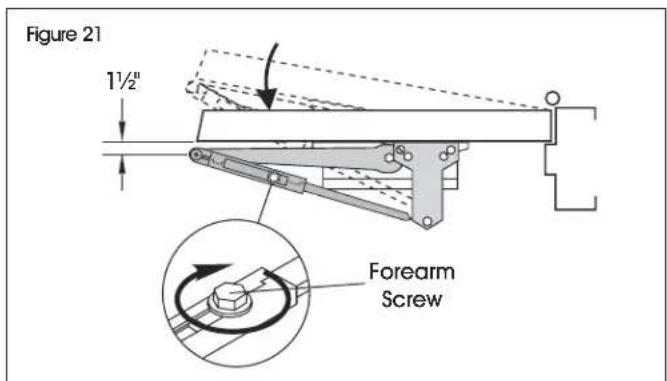
text_image
Figure 21 1½" Forearm Screw- Installation is complete. Proceed to page 8 for closer adjustments and decorative cap installation.
INSTALLATION CONTINUED
CLOSER ADJUSTMENTS

CAUTION! Do not turn speed adjusting valves more than two full turns counterclockwise. Do not back valves out of closer or a leak will result. (See Figure 22)
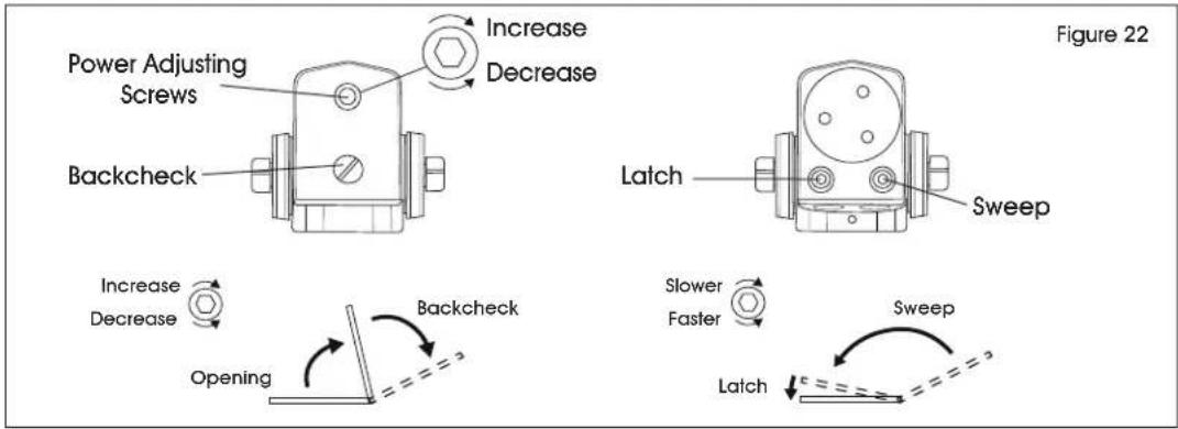
text_image
Power Adjusting Screws Increase Decrease Backcheck Figure 22 Latch Sweep Increase Decrease Backcheck Slower Faster Sweep Opening Latch| DOOR CLOSER SIZE | FULL TURNS OF POWER ADJUSTING SCREW | DOOR LEAF WIDTH | APPLICABLE DOOR WEIGHT | |
| INTERIOR EXTERIOR | ||||
| BF ---- 5 lb-f ---- | ||||
| 1 | -14 | 32" | 28" | 33-66 lbs |
| 2 | -10 | 36" | 32" | 33-99 lbs |
| 3 | 0 (Preset) | 42" | 36" | 99-143 lbs |
| 4 | +6 | 48" | 42" | 143-187 lbs |
*30 full (360°) turns maximum available.

IMPORTANT! By law, the Americans with Disabilities Act (ADA) may require that door closer installation comply with accessibility guidelines.
The closing force is adjustable from a size 1 to size 4 as outlined in ANSI Standard A156.4. When these series of door closers are installed and adjusted to conform to ADA reduced opening force requirements (5 lbs. max.) for interior doors, they may not have adequate closing force to reliably close and latch door. Power adjustments charted on this page are recommended where possible, to ensure proper door control.
PINION CAP INSTALLATION

NOTE: Do not over-tighten screws. (See Figures 23-25)
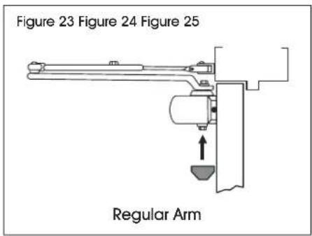
text_image
Figure 23 Figure 24 Figure 25 Regular Arm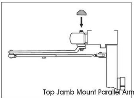
text_image
Top Jamb Mount Parallel Arm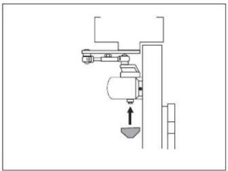
natural_image
Pure mechanical assembly diagram without any text, numbers, or symbolsULINE
ULINE H-11970
natural_image
Technical line drawing of a mechanical clamp or bracket assembly (no text or symbols)natural_image
Technical line drawing of a mechanical assembly with a downward force arrow (no text or symbols)ULINE
ULINE H-11970
NORTON ^MD – FERME-PORTE
USAGE LÉGER – BRAS RÉGULIER
1 800 295-5510
uline.ca
natural_image
Technical line drawing of a mechanical clamp or bracket assembly (no text or symbols)text_image
Sabot Bras Figure 9
text_image
Figure 10 Vis L Vis


