H-11978 - Door closer Uline - Free user manual and instructions
Find the device manual for free H-11978 Uline in PDF.

User questions about H-11978 Uline
0 question about this device. Answer the ones you know or ask your own.
Ask a new question about this device
Download the instructions for your Door closer in PDF format for free! Find your manual H-11978 - Uline and take your electronic device back in hand. On this page are published all the documents necessary for the use of your device. H-11978 by Uline.
USER MANUAL H-11978 Uline
ULINE H-11978, H-11979 DOOR CLOSER
1-800-295-5510 uline.com
natural_image
Technical line drawing of a mechanical latch or lever assembly (no text or symbols)TOOLS NEEDED

Two Person Assembly Recommended
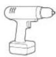
Drill
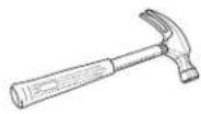
Hammer
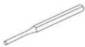
Center Punch
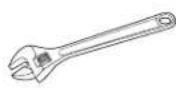
Adjustable Wrench
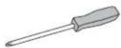
Phillips
Screwdriver
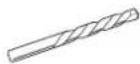
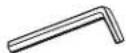
1/8" Drill Bit 3/32" Allen Wrench 5/32" Allen Wrench
PARTS
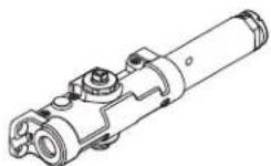
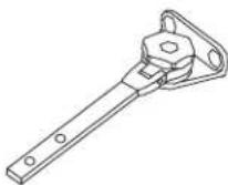
Closer x 1
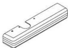
Cover x 1
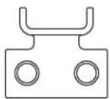
Mounting Bracket x 1
Shaft Cap x 1
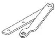
Arm x 1
Forearm x 1
(For H-11978)
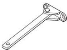
Hold-Open Arm x 1
(For H-11979)
1/2" Arm Attachment Screw x 1

Mounting Plate
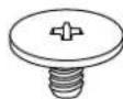
Machine Screw x 4
2" SRT
Mounting Screw x 1
1^3/8 SRT
Mounting Screw x 8

3/8" PA
Shoe Screw x 2

1/2" Arm Adjustment Screw x 1
natural_image
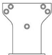
Pure technical line drawing of a symmetrical mechanical part with bolt holes (no text or symbols)Parallel Arm Shoe x 1
Fifth Screw Spacer x 1
SPECIFICATIONS
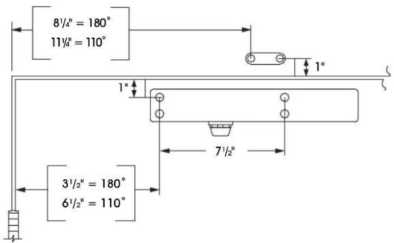
PULL SIDE MOUNTING
text_image
8½″ = 180° 11½″ = 110° 3½″ = 180° 6½″ = 110° 7½″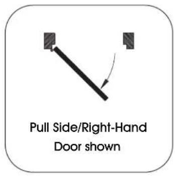
text_image
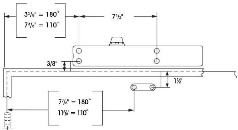
Pull Side/Right-Hand Door shownTOP JAMB MOUNTING
text_image
3⁵/₈" = 180° 7³/₈" = 110° 7¹/₂" 3/8" 7⁷/₈" = 180° 11⁵/₈" = 110° 1½"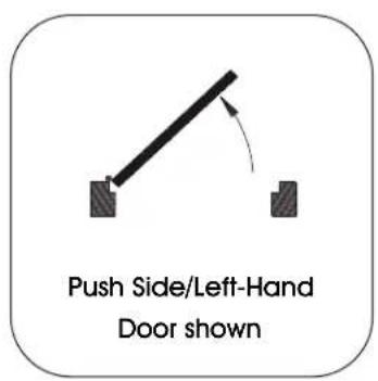
text_image
Push Side/Left-Hand Door shownSPECIFICATIONS CONTINUED
PARALLEL ARM MOUNTING
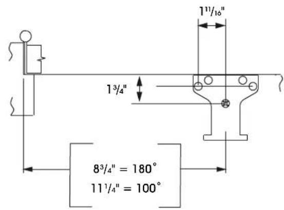
text_image
13/4" 83/4" = 180° 111/4" = 100°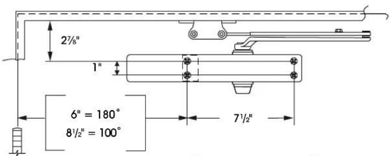
text_image
2½" 1" 6" = 180° 8½" = 100° 7½"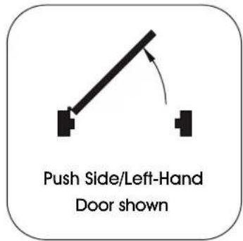
text_image
Push Side/Left-Hand Door shownSETUP

CAUTION! Improper installation or regulation may result in personal injury or property damage. Follow all instructions carefully.

IMPORTANT! Hold-open arms must not be installed on fire-rated doors.
- Door closer can be installed in three different locations on the door. Follow assembly instructions for desired installation location.
- The templates provided with this product are only compatible with doors installed with butt hinges. Call Uline Customer Service if door is installed using swing-clear hinges.
- Mount to 180^ to meet ADA requirements.
- For questions, call Uline Customer Service at 1-800-295-5510.
INSTRUCTIONS
For pull side installation, closer is installed on pull/hinge side of door. (See Figure 1)
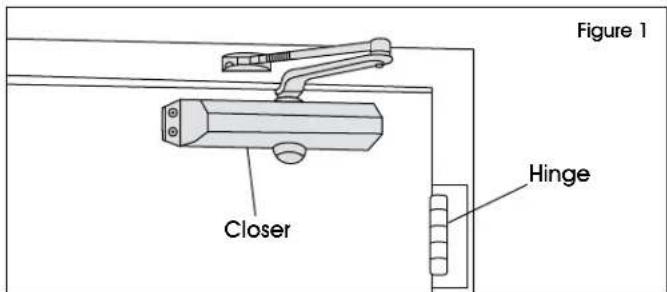
text_image
Figure 1 Closer Hinge- Locate proper template. Tear along dotted line, leaving one door template and one frame template. (See Figures 2-3)

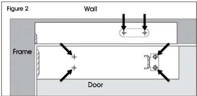
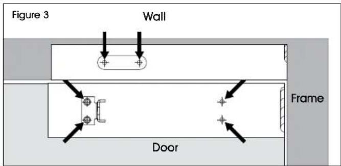
IMPORTANT! Figures 2-3 show 180° mounting. Align templates with the edge of the door on the hinged side.

IMPORTANT! For 110° mounting, align templates 3" in from the edge of the door on the hinged side.
- Center-punch four hole locations onto door and two onto frame. Remove template and drill 1/8" pilot holes into the punch locations. (See Figures 2-3)
RIGHT-HAND DOOR
text_image
Figure 2 Wall Frame DoorLEFT-HAND DOOR
text_image
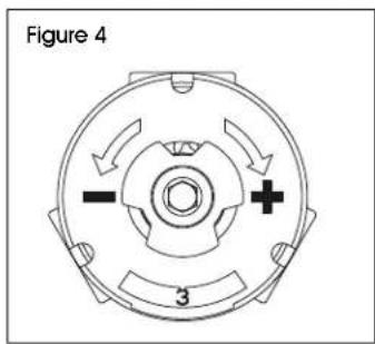
Figure 3 Wall Frame Door- Determine door width. With 5/32" Allen wrench, adjust spring power on closer cylinder to match chart below. (See Figure 4)
text_image
Figure 4 3| DOOR WIDTH POWER ADJUST | |
| SET TO: | |
| ADA 1 | |
| 30" 2 | |
| 32" 3 | |
| 36" 4 | |
| 42" 5 | |
| 48" 6 | |

IMPORTANT! Illustrations show installation on right-hand door. Instructions for left-hand doors are opposite.
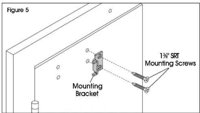
- Secure mounting bracket to previously drilled pilot holes using two 1 ^3/8 " SRT mounting screws. (See Figure 5)

NOTE: Ensure open side of bracket faces hinges.

NOTE: Reduce installation torque if using SRT screws in wood. The use of wood screws is recommended for wood installation.
text_image
Figure 5 Mounting Bracket 1¾" SRT Mounting ScrewsINSTALLATION CONTINUED
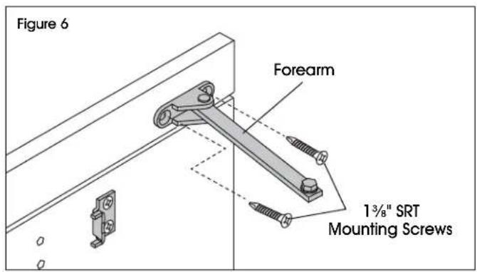
- Mount forearm to previously drilled pilot holes in frame/wall using two 1 ^3/8 " SRT mounting screws.
a. Standard forearm installation. (See Figure 6)
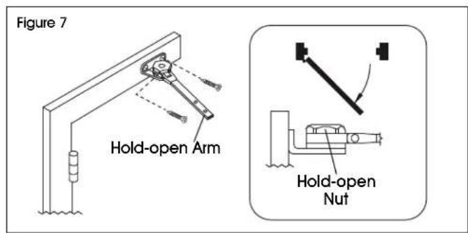
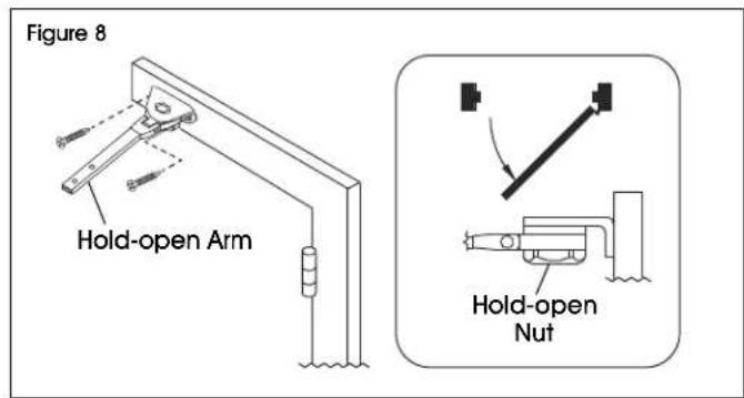
b. Hold-open arm installation. (See Figures 7-8)

NOTE: Identify direction of hold-open nut according to mounting before installing. (See Figure 7)
text_image
Figure 6 Forearm 1³/⁸" SRT Mounting ScrewsRIGHT-HAND DOOR
text_image
Figure 7 Hold-open Arm Hold-open NutLEFT-HAND DOOR
text_image
Figure 8 Hold-open Arm Hold-open Nut- Slide closer onto bracket. Once secure, align closer with previously drilled pilot holes. Secure with 1^3/_8 " SRT mounting screws. (See Figure 9)

text_image
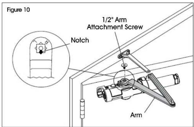
Figure 9 Closer Bracket 1 3/8" SRT Mounting Screws- Attach arm to the closer with 1/2" arm attachment screw. (See Figure 10)

NOTE: Ensure notch on pinion is aligned to arm as shown in Figure 10.
text_image
Figure 10 1/2" Arm Attachment Screw Notch Arm ArmINSTALLATION CONTINUED
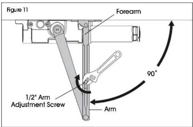
- Position forearm at 90° from the door. Slide forearm into arm and secure using 1/2" arm adjustment screw. (See Figure 11)
text_image
Figure 11 Forearm 1/2" Arm Adjustment Screw Arm 90°CLOSER ADJUSTMENTS
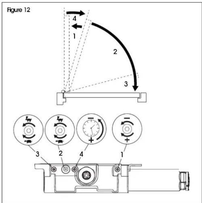
With 3/32" Allen wrench, adjust closer's delay action settings to your preference. (See Figure 12)

NOTE: A "normal" closing time from 90° open position is 5-7 seconds, evenly divided between main speed and latch speed.

CAUTION! Opening of adjustment valves too far may result in leakage of closer, personal injury or property damage. Follow all instructions carefully.
text_image
Figure 12 4 1 2 3 3 2 4 1| DELAY ACTION SETTINGS | ||
| # | SETTING ADJUSTMENT | |
| 1 Backcheck | Turn clockwise to increase.Turn counterclockwise to decrease. | |
| 2 Main Speed | Turn clockwise to slow speed.Turn counterclockwise to increase speed.. | |
| 3 Latch Speed | Turn clockwise to slow speed.Turn counterclockwise to increase speed. | |
| 4 Delay Speed | Turn clockwise to increase delay.Turn counterclockwise to decrease delay. | |
ADJUSTING HOLD-OPEN ARM
If hold-open arm is installed, it may need to be adjusted after assembly is completed.
- Loosen hold-open nut. (See Figure 13)
- Open door to desired position and tighten hold-open nut securely. (See Figure 13)
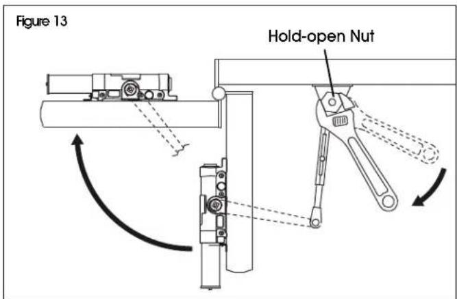
text_image
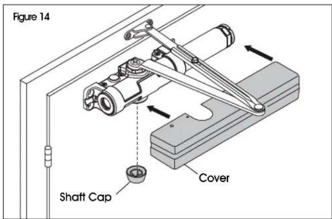
Figure 13 Hold-open Nut- Snap on cover and shaft cap. (See Figure 14)
text_image
Figure 14 Shaft Cap CoverINSTALLATION CONTINUED
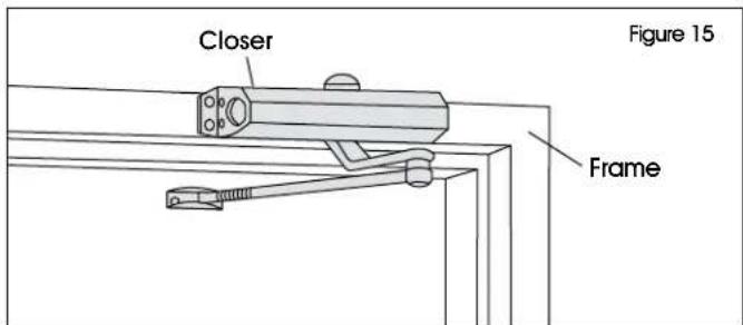
TOP JAMB INSTALLATION
For top jamb installation, closer is installed onto frame on push side of door. (See Figure 15)
text_image
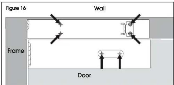
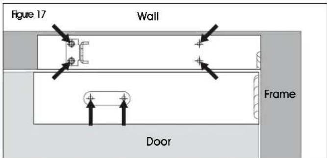
Closer Figure 15 Frame- Locate proper template. Tear along dotted line, leaving one door template and one frame template. (See Figures 16-17)

IMPORTANT! Figures 16-17 show 180° mounting. Align templates with the edge of the door on the hinged side.

IMPORTANT! For 110° mounting, align templates 3.75" in from the edge of the door on the hinged side.
- Center-punch four hole locations onto frame and two onto door. Remove template and drill 1/8" pilot holes into the punch locations. (See Figures 16-17)
LEFT-HAND DOOR
text_image
Figure 16 Wall Frame DoorRIGHT-HAND DOOR
text_image
Figure 17 Wall Frame Door- Determine door width. With 5/32" Allen wrench, adjust spring power on closer cylinder to match chart below. (See Figure 18)
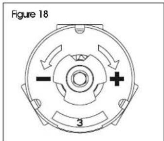
text_image
Figure 18 - + 3| DOOR WIDTH POWER ADJUST | |
| SET TO: | |
| ADA 1 | |
| 30" 2 | |
| 32" 3 | |
| 36" 4 | |
| 42" 5 | |
| 48" 6 | |

IMPORTANT! Illustrations show installation on left-hand door. Instructions for right-hand doors are opposite.
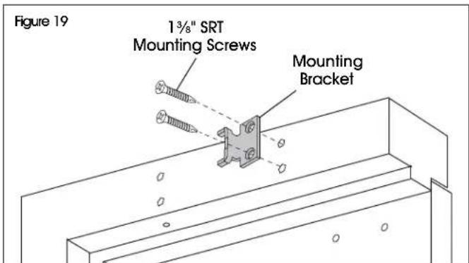
- Secure mounting bracket to previously drilled pilot holes in frame with two 1^3/_8 " SRT mounting screws. (See Figure 19)

NOTE: Ensure open side of bracket faces hinges.

NOTE: Reduce installation torque if using SRT screws in wood. The use of wood screws is recommended for wood.
text_image
Figure 19 1 ¾" SRT Mounting Screws Mounting BracketINSTALLATION CONTINUED
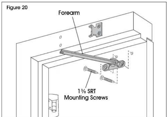
- Mount forearm to previously drilled pilot holes in door using two 1 ^3/8 " SRT mounting screws.
a. Standard Forearm installation. (See Figure 20)
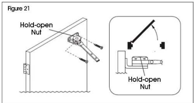
b. Hold-open arm installation. (See Figures 21-22)

NOTE: Identify direction of hold-open nut according to mounting before installing. (See Figures 21-22)
text_image
Figure 20 Forearm 1¾ SRT Mounting ScrewsLEFT-HAND DOOR
text_image
Figure 21 Hold-open Nut Hold-open NutRIGHT-HAND DOOR
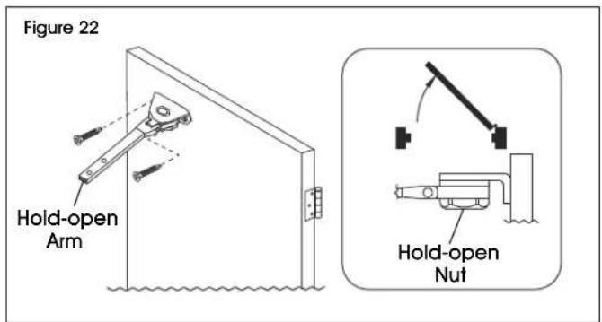
text_image
Figure 22 Hold-open Arm Hold-open Nut- Slide closer onto bracket. Once secure, align closer with previously drilled pilot holes. Secure with 1^3/_8 " SRT mounting screws. (See Figure 23)
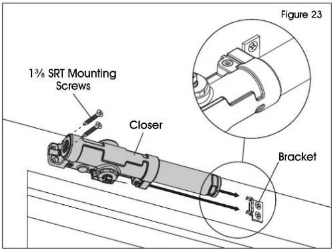
text_image
1¾ SRT Mounting Screws Closer Figure 23 Bracket- Attach arm to the closer. Align notch on pinion with arm and secure with 1/2" arm attachment screw. (See Figure 24)

NOTE: Ensure notch on pinion is aligned to arm as shown in Figure 24.
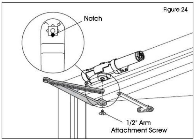
text_image
Figure 24 Notch 1/2" Arm Attachment ScrewINSTALLATION CONTINUED
- Position forearm at 90° from the door. Slide forearm into arm and secure using 1/2" arm adjustment screw. (See Figure 25)
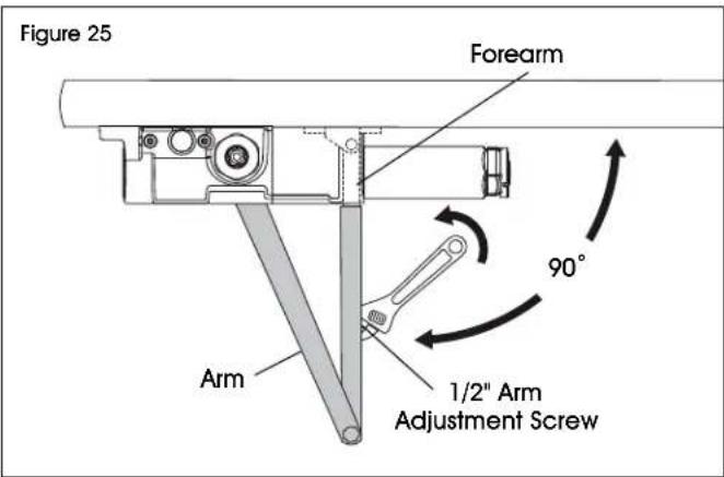
text_image
Figure 25 Forearm 90° Arm 1/2" Arm Adjustment ScrewCLOSER ADJUSTMENTS
With 3/32" Allen wrench, adjust closer's delay action settings to your preference. (See Figure 26)

NOTE: A "normal" closing time from 90° open position is 5-7 seconds, evenly divided between main speed and latch speed.

CAUTION! Opening of adjustment valves too far may result in leakage of closer, personal injury or property damage. Follow all instructions carefully.
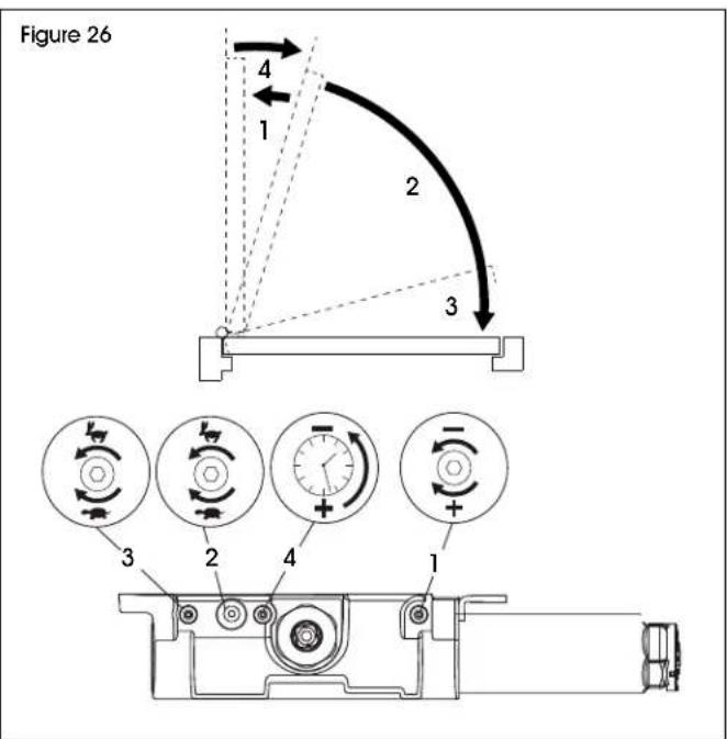
text_image
Figure 26 4 1 2 3 3 2 4 1| DELAY ACTION SETTINGS | ||
| # | SETTING ADJUSTMENT | |
| 1 Backcheck | Turn clockwise to increase.Turn counterclockwise to decrease. | |
| 2 Main Speed | Turn clockwise to slow speed.Turn counterclockwise to increase speed. | |
| 3 Latch Speed | Turn clockwise to slow speed.Turn counterclockwise to increase speed. | |
| 4 Delay Speed | Turn clockwise to increase delay.Turn counterclockwise to decrease delay. | |
ADJUSTING HOLD-OPEN ARM
If hold-open arm is installed, it may need to be adjusted after assembly is completed.
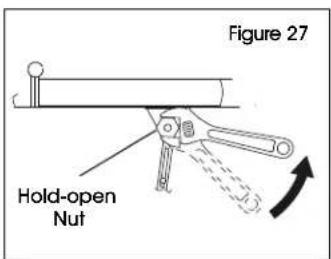
- Loosen hold-open nut. (See Figure 27)
text_image
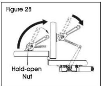
Figure 27 Hold-open Nut- Open door to desired position and tighten hold-open nut securely. (See Figure 28)
text_image
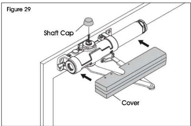
Figure 28 Hold-open Nut- Snap on cover and shaft cap. (See Figure 29)
text_image
Figure 29 Shaft Cap CoverINSTALLATION CONTINUED
PARALLEL ARM INSTALLATION
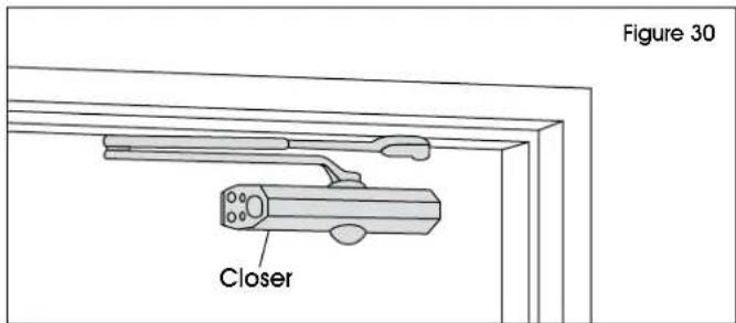
For parallel arm installation, closer is installed on push/stop side of door. (See Figure 30)
text_image
Figure 30 Closer- Locate proper template. Tear along dotted line, leaving one door template and one frame template. (See Figures 31-32)

NOTE: Red arrows should align when templates are properly placed.

IMPORTANT! Figures 31-32 show 180° mounting. Align templates with the edge of the door on the hinged side.

IMPORTANT! For 100° mounting, align templates 2.5" in from the edge of the door on the hinged side.
- Center-punch four hole locations onto door and five onto frame. Remove template and drill 1/8" pilot holes into the punch locations. (See Figures 31-32)
LEFT-HAND DOOR
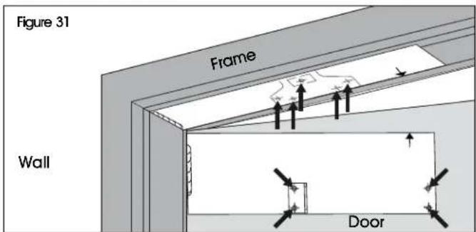
text_image
Figure 31 Frame Wall DoorRIGHT-HAND DOOR
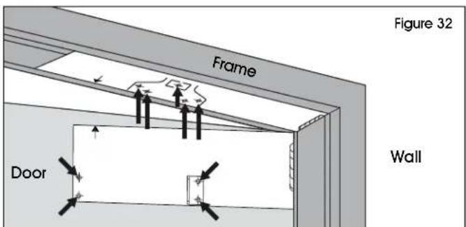
text_image
Figure 32 Frame Wall Door- Determine door width. With 5/32" Allen wrench, adjust spring power on closer cylinder to match chart below. (See Figure 33)
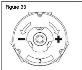
text_image
Figure 33 - + 3| DOOR WIDTH POWER ADJUST | |
| SET TO: | |
| ADA 1 | |
| 30" 2 | |
| 32" 3 | |
| 36" 4 | |
| 42" 5 | |
| 48" 6 | |

IMPORTANT! Illustrations show installation on left-hand door. Instructions for right-hand doors are opposite.
- Secure bracket and closer to door using previously drilled pilot holes with four 1 ^3/8 " SRT mounting screws. (See Figure 34-35)

NOTE: Reduce installation torque if using SRT mounting screws in wood. The use of wood screws is recommended for wood.
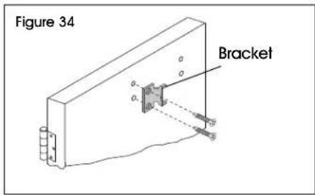
text_image
Figure 34 Bracket
text_image
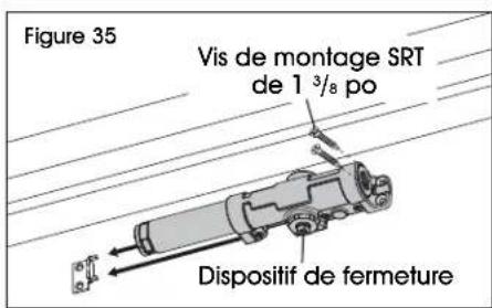
Figure 35 1³/⁸" SRT Mounting Screws CloserINSTALLATION CONTINUED
- Pre-load closer to 35° with adjustable wrench. (See Figure 36)
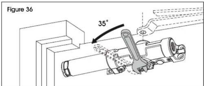
text_image
Figure 36 35°- Attach arm to the closer. Align notch on pinion with arm to corresponding L marking. Secure with 1/2" arm attachment screw. (See Figure 37)

NOTE: If installing on door with right-side hinges, align notch to R marking.
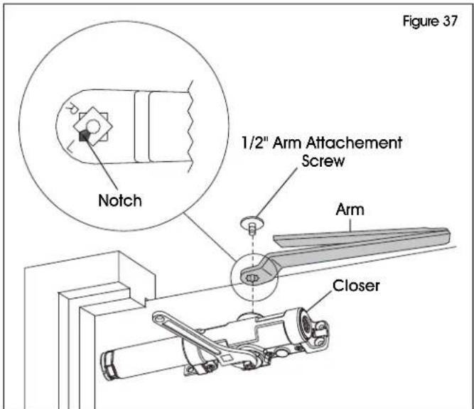
text_image
Figure 37 Notch 1/2" Arm Attachment Screw Arm Closer- Attach parallel arm shoe to door frame with four 1^3/8 SRT mounting screws and one 2" SRT mounting screw. Use fifth screw spacer to fill door frame gap. (See Figure 38)
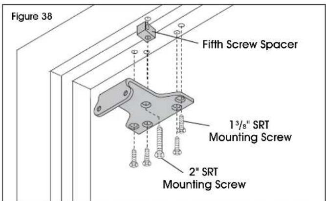
text_image
Figure 38 Fifth Screw Spacer 1 3/8" SRT Mounting Screw 2" SRT Mounting Screw- Attach forearm to parallel arm shoe using two 3/8" shoe screws.
a. Standard forearm installation. (See Figure 39)
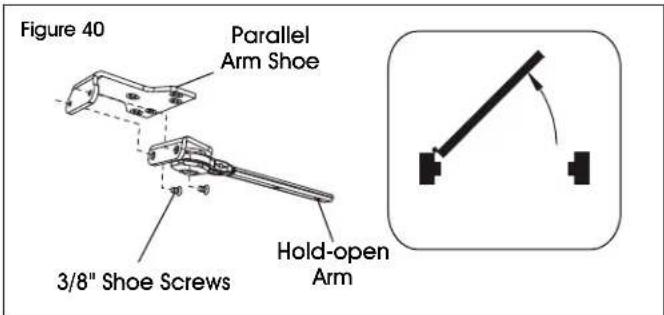
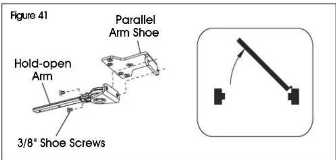
b. Hold-open arm installation. (See Figures 40-41)

NOTE: Identify direction of hold-open nut according to mounting before installing. (See Figure 40)
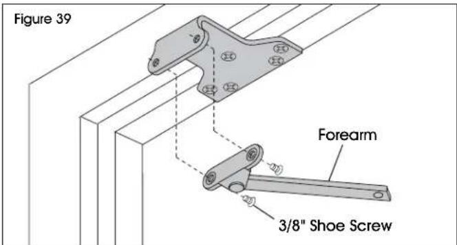
text_image
Figure 39 Forearm 3/8" Shoe ScrewLEFT-HAND DOOR
text_image
Figure 40 Parallel Arm Shoe 3/8" Shoe Screws Hold-open ArmRIGHT-HAND DOOR
text_image
Figure 41 Parallel Arm Shoe Hold-open Arm 3/8" Shoe ScrewsINSTALLATION CONTINUED
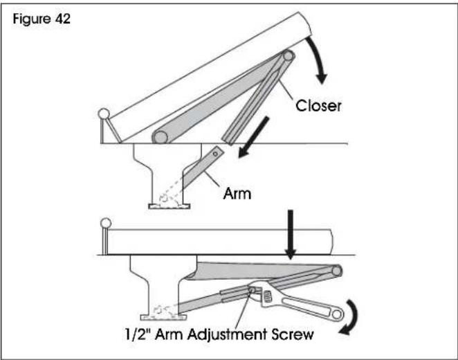
- Pre-load arm and secue to closer with 1/2" arm adjustment screw. (See Figure 42)
text_image
Figure 42 Closer Arm 1/2" Arm Adjustment ScrewCLOSER ADJUSTMENTS
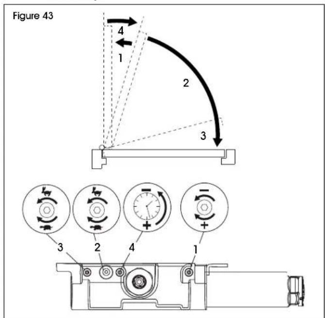
With 3/32" Allen wrench, adjust closer's delay action settings to your preference. (See Figure 43)

NOTE: A "normal" closing time from 90° open position is 5-7 seconds, evenly divided between main speed and latch speed.

CAUTION! Opening of regulation valves too far may result in leakage of closer, personal injury or property damage. Follow all instructions carefully.
text_image
Figure 43 1 2 3 4 3 2 4 1| DELAY ACTION SETTINGS | ||
| # | SETTING ADJUSTMENT | |
| 1 Backcheck | Turn clockwise to increase.Turn counterclockwise to decrease. | |
| 2 Main Speed | Turn clockwise to slow speed.Turn counterclockwise to increase speed. | |
| 3 Latch Speed | Turn clockwise to slow speed.Turn counterclockwise to increase speed. | |
| 4 Delay Speed | Turn clockwise to increase delay.Turn counterclockwise to decrease delay. | |
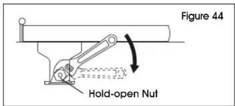
ADJUSTING HOLD-OPEN ARM
If hold-open arm is installed, it may need to be adjusted after assembly is completed.
- Loosen hold-open nut. (See Figure 44)
text_image
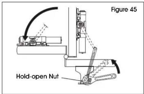
Figure 44 Hold-open Nut- Open door to desired position and tighten hold-open nut securely. (See Figure 45)
text_image
Figure 45 Hold-open Nut- Snap on cover and shaft cap. (See Figure 46)
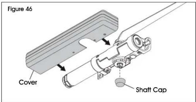
text_image
Figure 46 Cover Shaft Capnatural_image
Technical line drawing of a mechanical clamp or lever assembly (no text or symbols)natural_image
Simple line drawing of a symmetrical mechanical component with bolt holes (no text or symbols)1 Zapata de Brazo Paralelo
natural_image
Technical line drawing of a mechanical clamp or lever assembly (no text or symbols)OUTILS REQUIS

natural_image
Simple line drawing of a symmetrical mechanical component with bolt holes (no text or symbols)text_image
Figure 4 3| LARGEUR DE LA PORTE PUISSANCE DU RESSORT | |
| RÉGLER À : | |
| ADA 1 | |
| 30 po 2 | |
| 32 po 3 | |
| 36 po 4 | |
| 42 po 5 | |
| 48 po 6 | |

text_image
Figure 34 Support