DXCM009-0370 - Sandblasting cabinet DEWALT - Free user manual and instructions
Find the device manual for free DXCM009-0370 DEWALT in PDF.

User questions about DXCM009-0370 DEWALT
0 question about this device. Answer the ones you know or ask your own.
Ask a new question about this device
Download the instructions for your Sandblasting cabinet in PDF format for free! Find your manual DXCM009-0370 - DEWALT and take your electronic device back in hand. On this page are published all the documents necessary for the use of your device. DXCM009-0370 by DEWALT.
USER MANUAL DXCM009-0370 DEWALT
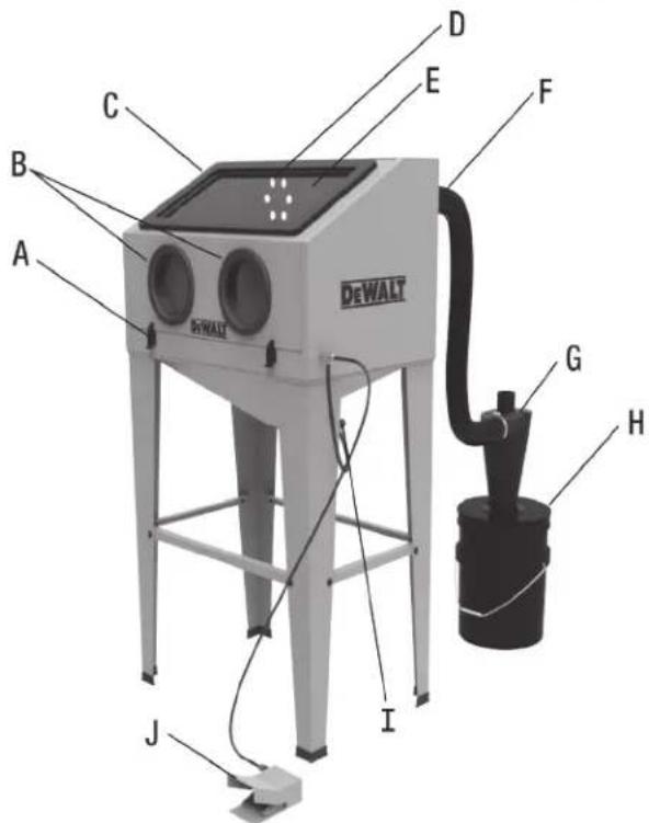
DXCM009-0370 Sand Blast Cabinet
General User Items Not associated with Parts List and
Assembly.
A. Door Latch
B. Glove Seats
C. Light Switch (Not Visible)
D. Cabinet Vent
E. View Window
F. Suction Hose
G. Cyclone
H. Bucket & Lid (Not Included)
I. Media Vibrator
J. Foot Control Pedal
K. Blast Gun (Inside Cabinet)
Specifications
| MODEL DXCM009-0370 | |
| NET WEIGHT 96 lbs. (44.5 kg) | |
| MAX. WORKING PRESSURE | 125 PSI |
| ABRASIVE CAPACITY 40 LBS | |
| AVG. AIR CONSUMPTION 20 | CFM @ 90 PSI |
| VIEW WINDOW 21"W x 10.5" | H |
| WORKING AREA 30" L x 19" | W x 18" H |
| OVERALL DIMENSIONS 34" L | x 22" W x 56.5" H |
| INCLUDED NOZZLES (2) 6mm | & (2) 7mm |
FIG. 1
text_image
DEWALT A B C D E F G H I JDefinitions: Safety Guidelines
The definitions below describe the level of severity for each signal word. Please read the manual and pay attention to these symbols.
▲ DANGER: Indicates an imminently hazardous situation which, if not avoided, will result in death or serious injury.
⚠ WARNING: Indicates a potentially hazardous situation which, if not avoided, could result in death or serious injury.
▲ CAUTION: Indicates a potentially hazardous situation which, if not avoided, may result in minor or moderate injury.
NOTICE: Indicates a practice not related to personal injury which, if not avoided, may result in property damage.
IF YOU HAVE ANY QUESTIONS OR COMMENTS ABOUT THIS OR ANY DEWALT TOOL, CALL US TOLL FREE AT: 1-888-895-4549
Important Safety
▲ WARNING: CONTAINS LEAD. May be harmful if eaten or chewed. May generate dust containing lead. Wash hands after use. Keep out of reach of children.
▲ WARNING: Some dust created by power sanding, sawing, grinding, drilling, and other construction activities contains chemicals known to the State of California to cause cancer, birth defects or other reproductive harm. Some example of these chemicals are:
- Lead from lead-based paints
- Crystalline silica from bricks and cement and other masonry products
- Arsenic and chromium from chemically-treated lumber
Your risk from these exposures varies, depending on how often you do this type of work. To reduce your exposure to these chemicals: work in a well ventilated area, and work with approved safety equipment, always wear OSHA/MSHA/NIOSH approved, properly fitting face mask or respirator when using such tools. When using air tools, basic safety precautions should always be followed to reduce the risk of personal injury.
⚠ WARNING: This product can expose you to chemicals including Lead, which are known to the State of California to cause cancer and birth defects or other reproductive harm. For more information go to www.P65Warnings.ca.gov.

Save these instructions
WARNING: Improper operation or maintenance of this product could result in serious injury and property damage. Read and understand all warnings and operating instructions before using this equipment. Read instruction manual for compressor prior to using this product. When using air tools, basic safety precautions should always be followed to reduce the risk of personal injury.
WARNING:

Operators and others in work area must wear ANSI Z87.1 CAN/CSA Z94.3 approved safety glasses with side shields.

Operators and others in work area must wear ear protection.
WARNING:
- Read all manuals included with this product carefully. Be thoroughly familiar with the controls and the proper use of the equipment.
- Any blast cabinet will produce a powerful flow of abrasive particles. To avoid personal injury and property damage, study this manual thoroughly before assembling,
operating or servicing this blast cabinet. Never point the abrasive blaster nozzle at anyone or object outside of cabinet. Do not use abrasive gun with door open.
- Do not exceed any pressure rating of any component in the system.
- Do not use damaged or worn attachments.
- During operation, do not expose hands or skin directly in the line of the blast nozzle.
- Keep all nuts, bolts and screws tight and ensure equipment is in safe working condition.
- Disconnect the cabinet from the air supply before changing accessories or attempting to install, service, relocate or perform any maintenance.
- Check hose and air lines for weak or worn condition before each use. Make sure all of the connections are secure before each use.

▲ DANGER: RISK OF EXPLOSION OR FIRE
- Fire or Explosion Hazard! DO NOT USE an abrasive blaster around combustible or flammable liquids, dust gases, oily rags or other materials that can explode or burn quickly. Some abrasives create sparks when they hit surfaces. Abrasives similar to aluminum oxide may generate static electric sparks which will cause fires or explosions in an unsafe environment.

▲ DANGER: RISK TO BREATHING (ASPHYXIATION)
- Dust can be created when you sweep, blast, cut, drill or grind materials such as wood, paint, metal, concrete, cement, or other masonry. This dust often contians chemicals known to cause cancer, birth defects or other reproductive harm. Make sure to wear protective gear.

CAUTION: RISK OF STATIC SHOCK
- Static electric shocks can be painful. Please wear leather or rubber soled shoes or boots and stand on the ground to avoid static electricity.
ADANGER: SILICOSIS AND OTHER DUST WARNINGS DO NOT USE SAND!
While the vacuum assisted reclaiming system on this product does a good job of dust containment, breathing dust from silica sand may cause silicosis, a fatal lung disease. Breathing dust during blasting operations may also cause asbestosis and/or other serious or fatal diseases.
A NIOSH-approved, well maintained abrasive blasting respirator must be used by anyone blasting, anyone handling or using media containing toxic substances or media with free crystalline silica and anyone in the area of the dust. Harmful dust can remain suspended in the air for long periods of time after blasting has ceased, causing serious injury or death.
Before removing respirator, use an air monitoring instrument to determine if the atmosphere is safe to breathe. Contact the local OSHA or NIOSH office to determine the proper respirator for your particular application.
READ THESE SAFETY PROCEDURES IN THEIR ENTIRETY PARTS OF THE OPERATING INSTRUCTIONS ARE WITHIN THESE WARNINGS.
These procedures are not intended to be exhaustive due to the many variables in the abrasive blasting field. Therefore, we INSIST that the hands, ears, mouth, nose and eyes be covered with the appropriate safety protection at all times.
Assembly Instructions with Indented Parts List
▲CAUTION: Two person lift and assembly is recommended! Injuries can occur when lifting and assembling heavy or large objects.
Tools Required for Assembly: NOT INCLUDED
Make sure to open carton from side marked "Open This Side"
• Phillips Screw Driver
- Flathead Screw Driver
- Adjustable Wrench
• 10mm, 13mm & 17mm Wrenches
- Drill with 14 " bit (for cyclone)
- 3" Hole Saw (or knife for cutting center hole in lid for cyclone)
A CAUTION: Make sure to wear the proper PPE such as gloves and safety glasses or goggles. Follow the safety warnings provided from the tool manufacturer.
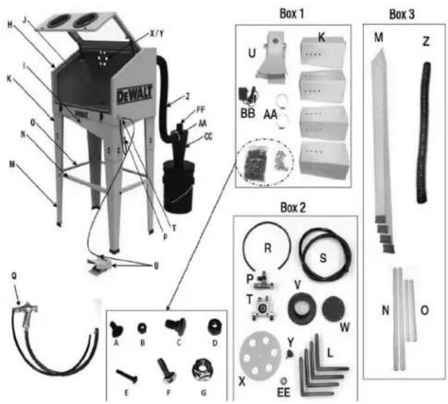
Labeled Parts View
Reference Parts List on Next Pages
Fig 2
text_image
H J X/Y DEWALT K I O N M Z FF AA CC P T U Q A B C D E F G Box 1 U K ... ... BB AA Box 2 R S P V T W Y L X EE N O Box 3 M Z* Exhaust Port Cover not needed if cyclone is installed.
| PARTS LIST | ||
| Item | Description QTY. | |
| A Bolt, M6 x 1.0 - 12mm, Black 32 | ||
| B 10mm Nut, Black 32 | ||
| C Carriage Bolt, M8 x 1.25 - 25mm, Black 16 | ||
| D 13mm Nut, Black 16 | ||
| E Bolt, M4 x 0.7 - 25 mm, Black 3 | ||
| F Bolt, M6 x 1.0 - 19mm, Zinc 6 | ||
| G 10mm Flange Lock Nuts, Zinc 6 | ||
| H Main cabinet assembly 1 | ||
| I Hopper 1 | ||
| J Grate 1 | ||
| K Short legs for benchtop configuration | 4 | |
| L Feet for short legs | 4 | |
| M | Long legs for stand alone configuration w/feet | 4 |
| N Cross support bracket – long | 2 | |
| O Cross support bracket – short | 2 | |
| P Manifold assembly with vibration adjustment valve | 1 | |
| Q | Gun/Hose Assy. w/6mm nozzle installed | 1 |
| R 6mm O.D. polyurethane tubing 20" | ||
| S 12mm O.D. polyurethane tubing 48" | ||
| T Vibration Module w/fasteners 1 | ||
| U Foot Valve Assembly 1 | ||
| V Exhaust Port 1 | ||
| W* Exhaust Port Cover 1 | ||
| X Vent 1 | ||
| Y Threaded Knob for Vent 1 | ||
| Z Suction hose, black 40" | ||
| AA 2 12 " Hose clamps | 2 | |
| BB | Power Supply for light | 1 |
| CC | Cyclone | 1 |
| DD | Cyclone gasket (not shown) | 1 |
| EE | Flat washer | 1 |
| FF | Hose Adaptor | 1 |
ADDITIONAL ITEMS NOT SHOWN:
• (2) Rolls of cabinet seal (extra seal for future use not needed for installation unless pre-installed seal damaged)
• (1) Extra 6mm nozzle and (2) 7mm nozzles
• (5) Window film sheets
• (1) Cyclone mounting template
(1) Gloves
ITEMS NOT INCLUDED:
- Teflon tape
• 5 Gallon bucket w/lid - Shop Vacuum
- Abrasive Media
Unit Assembly Instructions: Use the parts list and Fig 2 for reference when assembling. Also, it is recommended that you use two people with lifting and assembling this product.
- Open box and remove all components from inside of box and from the main cabinet assembly. Open all smaller boxes and place all components on the floor in an orderly fashion.
- Lay the main cabinet assembly (H) on its back using a blanket (or some other material) to prevent scratching during assembly. Carefully open both latches and slowly open the door.
-
Locate hopper (I) and orient it with the holes on the right side of the cabinet as shown on next page.
-
Place the cavity side of the hopper against the bottom of the cabinet and align the holes. Insert (6) bolts (A) from the inside of the cabinet in the locations shown below. Push the bolts through the seal material and install nuts (B). Do not tighten.

text_image
Make sure the hopper is oriented with these holes on the right side- Install the short legs (K) by placing at one of the base corners and align the holes. Insert bolt (A) from the inside of the cabinet into the (4) mounting holes. Push the bolts through the seal material and install nuts (B). Do not tighten. Repeat process for the other (3) legs. Once all (4) legs are installed, tighten all fasteners securing legs and hopper to cabinet. Close and latch door.
Determine if your cabinet will be configured as a benchtop model or as a stand alone floor model. For benchtop configuration, install feet (L) onto bottom of the legs and proceed to Step 9. For a stand alone floor model, continue to Step 6.
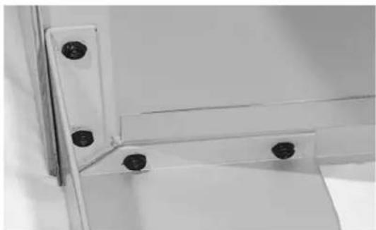
natural_image
Close-up of a metal bracket with four bolt holes (no text or symbols visible)- Install the long legs (M) to the inside of the short legs using (4) of bolt (C) and nut (D) using the (2) inner holes of the short leg. Repeat with the other (3) legs and tighten all fasteners.
natural_image
Close-up of a white electronic device with a control panel and indicator lights (no visible text or symbols)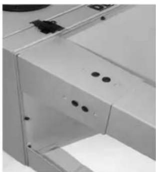
natural_image
Close-up of a white industrial machine handle with mounting holes and a circular component (no visible text or symbols)-
With a helper, carefully stand the cabinet upright. Stand in front of the cabinet and insert your hands into the gloves. Determine if the height of the cabinet is comfortable at this setting. If you feel that the cabinet is too high or too low, carefully lay the cabinet on the floor on its back (with a helper). Remove the fasteners securing the long legs to the short legs and slide the (4) long legs up one hole location if the cabinet seems too high or down one hole location if the cabinet seems too low. Reinstall all fasteners and tighten. Using a helper, carefully stand the cabinet upright and recheck to see if the height is correct.
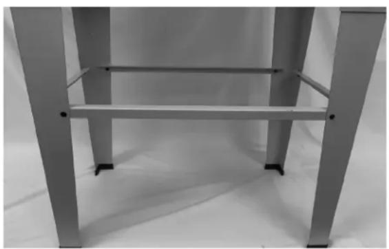
-
Using bolt (A) and nut (B), install the (2) long cross supports (N) and (2) short cross supports (O) on the inside surfaces of the legs. Place the nuts on the inside of the legs as shown but do not tighten. After all (4) cross supports are installed, tighten all fasteners.
natural_image
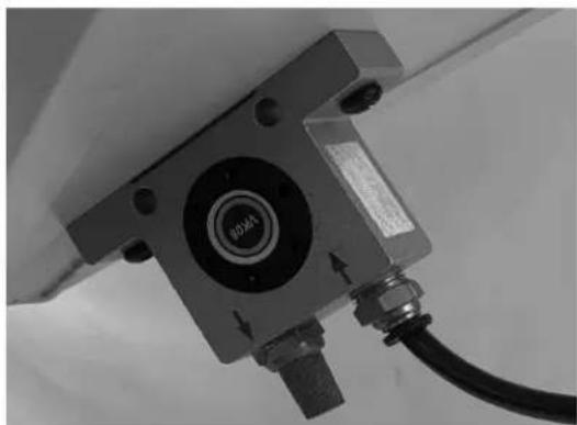
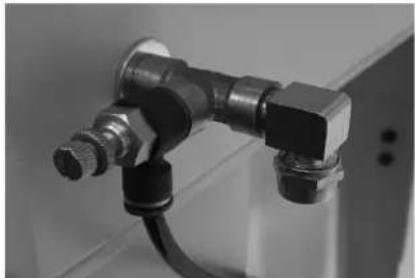
Close-up of a metallic chair or stool with metal legs and horizontal ribs (no text or symbols visible)- Unlatch and open cabinet door. Locate the manifold assembly (P) and remove the compression nut, straight fitting and the flat washer. Set the compression nut aside for use in the next step. Apply 2-3 wraps of Teflon tape to the threads on the straight fitting. Insert threads of straight fitting from the inside of the cabinet through the hole located on the lower right side. Install flat washer on the outside of the cabinet. Assemble the manifold assembly to the fitting and tighten. Orient manifold assembly with push lock fitting and compression fitting elbow pointing down.
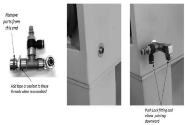
- Locate gun assembly (Q) and place inside cabinet. Using the compression nut you removed from the manifold assembly, slide nut onto the gun's polyurethane tubing in the orientation as shown below. Firmly push the tubing onto the compression fitting until it is seated fully against the shoulder. While holding the tubing in place, tighten the compression nut until snug. Do not overtighten.
natural_image
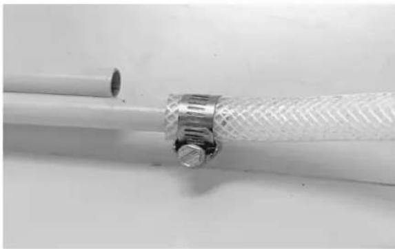
Close-up of a black and metallic pipe fitting with threaded connectors, partially installed (no text or symbols visible)- Slide the suction hose from the gun over the suction pickup tube (the longer tube as shown). Hose should be inserted approximately one inch onto tube. Secure hose by tightening hose clamp.
natural_image
Close-up of a white cable with a mesh cap and metal connector, no visible text or symbols- Install vibration module (T) onto the bottom right of hopper using the fasteners provided with it. Orient the module with the push lock fitting on the right side as shown below. Tighten fasteners securely. Insert the 6mm polyurethane tubing (R) into the fitting and push in until it is seated fully. Insert the other end of the tubing into the push lock fitting on the manifold assembly (P).
natural_image
Close-up of a mechanical component with a central circular button and cable, no visible text or symbols.- Carefully pull gun assembly outside of the cabinet and let hang. Locate grate (J) and orient it face up with the (3) supports on the bottom. Turn grate at an angle with notched corner at front right and insert it into the cabinet as shown below. Once the grate is inside the cabinet, lay it flat on the bottom and return the gun assembly to the inside of the cabinet.
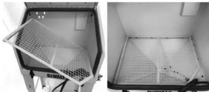
natural_image
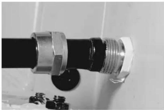
Two views of a double-decker industrial machine with mesh grating (no visible text or symbols)- Locate the foot valve assembly (U) and remove compression nut from the fitting. Locate the 12mm polyurethane tubing (S) and slide nut onto tubing in the orientation as shown. Firmly push the tubing onto the compression fitting until it is seated fully against the shoulder. While holding the tubing in place, tighten the compression nut until snug. Do not overtighten.
natural_image
Two views of a mechanical component with circular features and a cylindrical pin inserted (no text or symbols visible)- Remove compression nut from the elbow fitting on the manifold assembly (P). Slide nut onto tubing in the orientation as shown. Firmly push the tubing onto the compression fitting until it is seated fully against the shoulder. While holding the tubing in place, tighten the compression nut until snug. Do not overtighten.
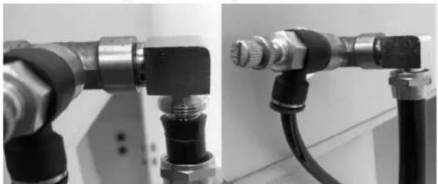
natural_image
Close-up of two industrial pipe fittings with black and metallic components, no visible text or symbols-
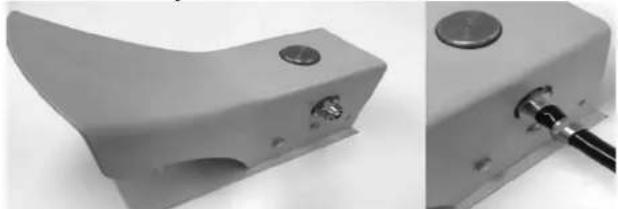
From outside rear of cabinet locate rear vent panel (X), threaded knob (Y) and flat washer (EE). Insert threaded portion of knob through center hole of vent panel. Place washer onto threads and install vent panel using threaded knob. The flat washer should be between the vent panel and the back of the cabinet. Tighten the knob securely. Align the holes of the panel with those in the cabinet.
-
From the outside rear of cabinet locate rear exhaust port (V) and install in the orientation as shown. Using (3) of bolt (E), attach port to cabinet and tighten securely.

text_image
Step 17 V E Step 16 EE X Y- Locate suction hose (Z) and (1) hose clamp (AA). Slide hose clamp onto one end of the hose. Slide hose and clamp together over the exhaust port and tighten hose clamp securely.

text_image
Step 18 AA Z- Cyclone setup: Using the provided template, cut the hole pattern in a 5 gallon bucket lid (Not Included.) Using (6) each of bolts (F) and nuts (G), install cyclone (CC) w/gasket (DD) onto bucket lid and tighten fasteners. Fasten lid onto bucket (not included.)
- Slide one hose clamp (AA) on the suction hose (Z). Slide hose and clamp together onto the side port of the cyclone and tighten hose clamp securely.
- Connect vacuum hose with cyclone adapter (FF) to top port of cyclone.
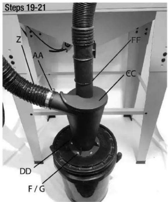
text_image
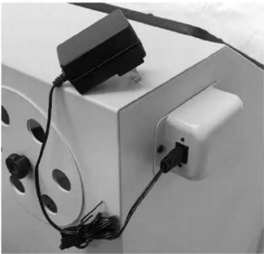
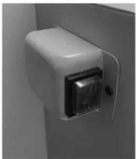
Steps 19-21 Z AA FF CC DD F / G- Locate power supply (BB) and plug cord into back of light switch. Insert power supply plug into 120V receptacle.
natural_image
Close-up of a white electronic device with a black plug and cable, no visible text or symbolsMAINTENANCE AND CLEANING
WARNING: Disconnect power and air before the maintenance is performed. Never perform any maintenance with the cabinet under pressure.
Cleaning: Please clean the blast cabinet or parts with a soft cloth. DO NOT use any solvents to clean the blast cabinet or parts inside of the cabinet. If the viewing window becomes such that the work area cannot be viewed, peel off the window protector film included with this unit and replace with new window protector film.
Air Supply Maintenance: Every day maintain the air supply according to the manufacturer's instructions. Drain the moisture from the filter and compressor regularly.
Performing routine air supply maintenance will reduce moisture contamination of abrasive media which will increase performance.
Before operation check fittings and hoses making sure all connections are leak free.
⚠ WARNING: Inspect gloves and make sure there are no punctures. If you feel air blowing in the glove, replace them immediately. DO NOT use a damaged or punctured glove.
Adding abrasive: Do not overfill. See specifications for maximum abrasive amount.
Abrasives: Use good quality, dry abrasives that are designed to be recycled. Keep abrasives dry. Moisture from the air source will cause clogging, flow problems and may cause component failure that is not covered under warranty. Replace abrasive media when the abrasive breaks down. Worn abrasive will reduce performance. DO NOT USE SAND!
CAUTION: Wear ANSI-approved safety goggles and NIOSH-approved dust mask / respirator when emptying the abrasive.
Changing abrasive: Place a container (not included), which is large enough to hold all abrasive, under the cabinet. Remove drain plug and empty abrasive into the container. Clear all abrasive out in order to prevent breakdown for the next operation. Replace drain plug.
Abrasive Storage: Store abrasives in sealed container and in a dry location. Abrasive media is susceptible to moisture.
Avoid clogging abrasive: Keep abrasive dry! Nozzle size should be 3-4 times larger than the size of the abrasive being used. If abrasive stops flowing, disconnect air supply and check for obstructions in the suction line and nozzle.
OPERATION INSTRUCTIONS:
Note: When using your abrasive blast cabinet, a compressor with 20 SCFM @ 90 PSI is recommended with a fine grade abrasive (See Media Guide for Types and Uses). If the specified compressor is not available, a smaller compressor can be used intermittently for the blasting operation. Read your compressor manual to determine duty cycle.
Connect the air compressor. Set the compressor pressure regulator to 90 PSI. Do not exceed maximum pressure rating. See specifications for SCFM and Maximum PSI requirements.
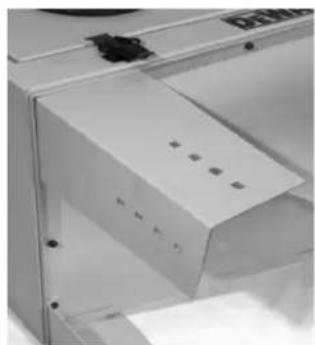
Turn the cabinet light on. This blast cabinet is equipped with LED cabinet work light.
natural_image
Close-up of a white appliance with a metallic button and indicator lights, mounted on a door (no visible text or symbols)Open the Blast Cabinet Door and fill the cabinet with fine abrasive material. Do not overfill. (See specifications for max abrasive capacity.)
Place the workpiece in the center of the cabinet. Close the cabinet door and latch securely. Turn shop vacuum on for the recovery of media and better working visibility.
Note: When using a shop vacuum, clean the filter periodically to maintain adequate suction and effectiveness of the vacuum. Read and understand shop vacuum owners manual. Insert your hands into the gloves. Be certain your fingers are properly positioned and you can move your hands easily and grip the workpiece comfortably.
Depress foot control pedal to operate the gun. Hold the work piece, and position your fingers so that the glove is not in the way of the workpiece. Reposition the workpiece as needed in order to access the complete surface area.
Use a circular motion or side-to-side motion. The nozzle should be approximately 2 inches away from the work piece.
This unit is equipped with a cabinet abrasive media vibrator. If abrasive media is not funneling to the bottom of the cabinet to the pickup tube, adjust vibrator by turning the control knob counter clockwise for increased vibration and clockwise for reduced vibration.
natural_image
Close-up of a mechanical pipe fitting with threaded connectors and a coiled cable (no visible text or symbols)Blast Cabinet Vent: Adjust cabinet vent to change pressure in cabinet. Opening vent will decrease cabinet pressure and closing the vent will increase cabinet pressure.
natural_image
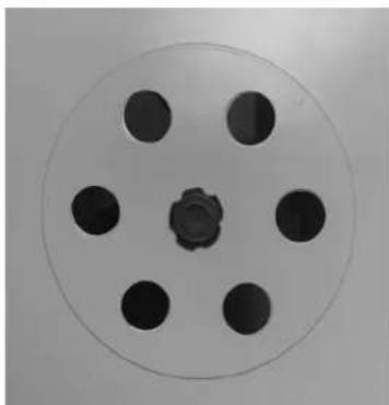
Circular object with six evenly spaced black holes and a central hole, resembling a film reel or marker (no text or symbols visible)Once the workpiece is completed, remove your hands from the gloves & turn the blast cabinet and shop vacuum off.
See maintenance and cleaning section when the job is completed.
Service and Adjustments
NOTE: ALL MAINTENANCE AND REPAIR OPERATIONS MUST BE PERFORMED BY TRAINED SERVICE TECHNICIAN.
⚠ WARNING: Risk of unsafe operation. When servicing, you may be exposed to voltage sources, compressed air, or moving parts. Before servicing unit, disconnect power and air supply to the unit.
Additional Service
Disassembly or service of the product beyond what is covered in this manual is not recommended. If additional service is required, contact your nearest Authorized Warranty Service Center.
Accessories
Recommended accessories for use with your tool are available for purchase from your local dealer or authorized service center. If you need assistance in locating any accessory for your tool, please call 1-888-895-4549 or visit our website www.dewalt.com.
Service Information
Please have the following information available for all service calls: Model Number ____ Serial Number ____ Date and Place of Purchase ____
Repairs
To assure product SAFETY and RELIABILITY, repairs, maintenance and adjustment should be performed by a DEWALT factory service center, a DEWALT authorized service center or other qualified service personnel. Always use genuine replacement parts.
Limited Warranty
DEWALT Industrial Tools are warranted from date of purchase.
1 Year – Limited on all sand blast tools. This warranty is not transferable to subsequent owners.
DEWALT will repair or replace, without charge, at DEWALT's option, any defects due to faulty materials or workmanship. For further detail of warranty coverage and warranty repair information, call 1-(888)-895-4549 or visit dewalt.com. This warranty does not apply to accessories or damage caused where repairs have been made or attempted by others. This warranty also does not apply to merchandise sold by DEWALT which has been manufactured by and identified as the product of another company, such as gasoline engines. Such manufacturer's warranty, if any, will apply. ANY INCIDENTAL, INDIRECT OR CONSEQUENTIAL LOSS, DAMAGE OR EXPENSE THAT MAY RESULT FROM ANY DEFECT, FAILURE OR MALFUNCTION OF THE PRODUCT IS NOT COVERED BY THIS WARRANTY. Some states do not allow the exclusion of limitation of incidental or consequential damages, so the above limitation or explosion my not apply to you.
IMPLIED WARRANTIES, INCLUDING THOSE OF MERCHANTABILITY OR FITNESS FOR A PARTICULAR PURPOSE, ARE LIMITED TO ONE YEAR FROM THE DATE OF ORIGINAL PURCHASE. Some states do not allow limitations on how long an implied warranty last, so the above limitations may not apply to you.
What the Company Will Do: (the company) will cover parts and labor to remedy substantial defects due to materials and workmanship during the first year of ownership, with the exceptions noted below. Parts used in repair of whole goods or accessories are warranted for the balance of the original warranty period.
What is not covered Under This Warranty? Failures by the original retail purchaser to install, maintain, and operate said equipment in accordance with standard industry practices. Modifications to the product, or tampering with components, or failure to comply with the specific recommendations of the Company set forth in the owner's manual, will render this warranty null and void. The Company shall not be liable for any repairs, replacements, or adjustments to the equipment, or any costs for labor performed by the purchaser without the Company's prior written approval. The effects of corrosion, erosion, surrounding environmental conditions, cosmetic defects, and routine maintenance items, are specifically
excluded from this warranty. Routine maintenance items fall under the owner's responsibility. Additional exclusions include: freight damage, failures resulting from neglect, accident, or abuse, induction motors when operated from a generator, oil leaks, air leaks, oil consumption, leaky fittings, hoses, drain valves, bleeder tubes, and outlet tubes.
- The following components are considered normal wear items and are not covered after the first year of ownership: gloves, window film, nozzles, electric motors, brushes, tubing, hoses, fittings, fasteners, wheels, gaskets, seals and air filter housings.
- Time required for orientation training for the service center to gain access to the product, or additional time due to inadequate egress.
- Damage caused from inadequate filter maintenance.
How do You Get Service? In order to be eligible for service under this warranty you must be the original retail purchaser, and provide proof of purchase from one of the Company's dealers, distributors, or retail outlet stores.
THIS WARRANTY GIVES YOU SPECIFIC LEGAL RIGHTS, AND YOU MAY ALSO HAVE OTHER RIGHTS WHICH VARY FROM STATE TO STATE.
THE COMPANY MAKES NO OTHER WARRANTY OR REPRESENTATION OF ANY KIND WHATSOEVER, EXPRESSED OR IMPLIED, EXCEPT THAT OF TITLE. ALL IMPLIED WARRANTIES, INCLUDING ANY WARRANTY OF MERCHANTABILITY AND FITNESS FOR PARTICULAR PURPOSE ARE HEREBY DISCLAIMED. LIABILITY FOR CONSEQUENTIAL AND INCIDENTAL DAMAGES UNDER ANY AND ALL WARRANTIES, OTHER CONTRACTS, NEGLEGENCE, OR OTHER TORTS IS EXCLUDED TO THE EXTENT EXCLUSION IS PERMITTED BY LAW.
FREE WARNING LABEL REPLACEMENT: If your warning labels become illegible or are missing, call 1-888-895-4549 for a free replacement.
TROUBLESHOOTING GUIDE
This section provides a list of the more frequently encountered malfunctions, their causes and corrective actions. The operator or maintenance personnel can perform some corrective actions, and others may require the assistance of a qualified DEWALT technician or your dealer.
Problem Code
Decrease in Performance ....1
Abrasive Media does not Fire From Gun ......2
Cabinet Light does Not Work 3
Visibility Issue....4
⚠ WARNING: Disconnect power and air before the maintenance is performed. Never perform any maintenance with the cabinet under pressure.
| Code Possible Cause Possible Solution | ||
| 1 | Not enough air pressure and/or air flow.Air leaking from loose connection.Abrasive media level too low.Abrasive media worn.Moisture in abrasive.Lubrication being used.Gun Blockage. | Check for loose connections and make sure that air supply is providing enough air flow (CFM) at required pressure (PSI) to the tool's air inlet. Do not exceed maximum air pressure.Verify all connections are leak free.Verify unit is filled with enough abrasive to operate correctly.Change abrasive if worn or too fine.Air must be clean and dry. Check inline filter. An oiler system should not be used with this tool. The oil will mix with the abrasive and cause a clog.Disconnect air supply. Unscrew gun tip and remove nozzle to check for blockage. Check for obstruction in suction tube and/or pickup tube in hopper. |
| Code | Possible Cause Possible Solution | |
| 2 | Lubrication used.Abrasive media size too large for nozzle.Abrasive media too moist and is sticking together. | An oiler system should not be used with this tool. The oil will mix with the abrasive and cause a clog.Replace nozzle with a nozzle large enough to handle abrasive media size or use finer media.Replace media with dry, fresh media. |
| 3 | Bulb is burned out.Power cord is not plugged in.Power switch is off.Outlet is non-functioning. | Replace light bulb.Check that the power cord is properly plugged into a working outlet.Turn the red light power switch on.Have the electrical outlet serviced by a qualified electrician. |
| 4 | Cabinet and viewing window has not been cleaned.Abrasive has tarnished the viewing window.Foggy or impaired view during use. | Clean cabinet and viewing window. Refer to page 14 maintenance and cleaning.Peel off the clear damaged window film and replace with new clean window film. (Extra film included)Make sure shop vacuum is on and connected to cyclone. |
DXCM009-0370 Enceinte de sablage
text_image
C B A DEWALT D E F G H J Itext_image
H J X/Y K I O N M DEWALT Z FF AA CC P T U Q Boîte 1 U K BB AA Boîte 2 R S P V T W Y L X EE N O Boîte 3 M ZARTICLES NON INCLUS :
natural_image
Close-up of a metal bracket with four bolts and mounting holes (no text or symbols visible)natural_image
Close-up of a white appliance with a lid and buttons, no visible text or symbols
natural_image
Close-up of a metallic mechanical component with mounting holes and a circular detail (no visible text or symbols)natural_image
Close-up of a metallic chair or stool with visible legs and feet, no text or symbols present.natural_image
Close-up of a white cabinet or fixture with a circular button and mounting bracket (no visible text or symbols)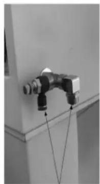
natural_image
Close-up of a mechanical pipe fitting mounted on a wall, with no visible text or symbolsnatural_image
Close-up of a black and metallic pipe fitting with threaded connectors (no text or symbols visible)natural_image
Close-up of a white plastic hose with a mesh cap and metal connector (no text or symbols visible)natural_image
Close-up of a mechanical component with a circular dial and cable, no visible text or symbolsnatural_image
Interior view of a microwave oven with a mesh grating and ventilation duct (no text or symbols visible)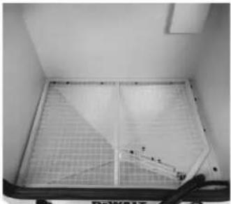
natural_image
Interior view of a double-door refrigerator with metal grating and ventilation grilles (no visible text or symbols)natural_image
Close-up of a gray metal mechanical component with a circular button and a threaded end (no visible text or symbols)natural_image
Close-up of two industrial robotic arms with black and metallic fittings, no visible text or symbolsnatural_image
Close-up of a white electronic device with a black plastic component and cable, no visible text or symbolsENTRETIEN ET NETTOYAGE
natural_image
Close-up of a white appliance with a digital display on its side (no visible text or symbols)natural_image
Close-up of a mechanical joint or connector with threaded connectors and a curved cable (no visible text or symbols)natural_image
Circular object with six evenly spaced black holes and a central knob, resembling a film reel or marker (no text or symbols visible)text_image
DeWALT A B C D E F G H I Jtext_image
Caja 1 Caja 3 DEWALT X/Y H J K I O N M Z FF M CC U P T Q R S U K BB AA Caja 2 M Z P V T W Y L X EE N Onatural_image
Close-up of a metal bracket with four bolt holes (no text or symbols visible)natural_image
Close-up of a white appliance with buttons and ventilation slots (no visible text or symbols)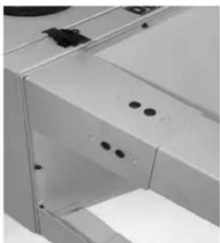
natural_image
Close-up of a white industrial machine handle with mounting holes and a circular component (no visible text or symbols)natural_image
Close-up of a metallic chair or stool with metal legs and a horizontal bar, no visible text or symbolsnatural_image
Close-up of a white wall corner with a metallic circular fixture and cable (no text or symbols visible)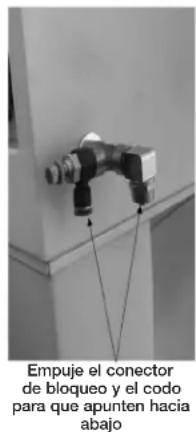
natural_image
Close-up of a black and metallic pipe fitting with threaded connectors, mounted on a white surface (no text or symbols visible)natural_image
Close-up of a white plastic hose with a mesh cap and metal connector (no text or symbols visible)natural_image
Close-up of a mechanical component with a central circular button labeled '4025' and a black cable (no readable text or symbols beyond the label)natural_image
Interior view of a microwave oven with a mesh grating and ventilation slots (no visible text or symbols)
natural_image
Interior view of a double-door refrigerator with metal grating and ventilation grilles (no visible text or symbols)natural_image
Two views of a mechanical component with circular features and a metallic knob inserted (no text or symbols visible)natural_image
Close-up of two industrial robotic arms with fittings and connectors (no visible text or symbols)text_image
Paso 17 V E Paso 16 EE X Ytext_image
Paso 18 AA Ztext_image
Pasos 19 a 21 Z AA FF CC DD F / Gnatural_image
Close-up of a white electronic device with a black plastic component and cable, no visible text or symbolsMANTENIMIENTO Y LIMPIEZA
natural_image
Close-up of a white wall-mounted electrical outlet or switch component (no visible text or symbols)natural_image
Close-up of a mechanical pipe fitting with threaded connectors (no visible text or symbols)natural_image
Circular object with six evenly spaced black holes and a central knob, resembling a film reel or mechanical component (no text or symbols visible)Under license from DEWALT Industrial Tool Co.
Bojo licencia de DEWALT Industrial Tool Co.
Sous licence de DEWALT Industrial Tool Co.
The following are trademarks for one or more DEWALT power tools: thee yellow and black color scheme; the "D" shaped air intake grill; the array of pyramids on the handgrip; the kit box configuration; and the array of lozenge shape humps on the surface of the tool.