DXCMH5593011 - Pressure washer DEWALT - Free user manual and instructions
Find the device manual for free DXCMH5593011 DEWALT in PDF.

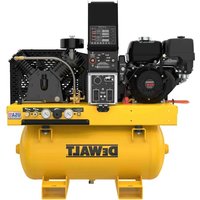
| Product Type | Gasoline air compressor, single stage, belt drive |
| Brand | DeWALT |
| Model | DXCMH5593011 |
| Dimensions (L x W x H) | 1066.80 x 463.04 x 876.81 mm |
| Weight | 99.80 kg |
| Air tank capacity | 113.6 L (30 gallons) |
| Maximum pressure | 175 psi (12.1 bar) |
| Pump type | Vertical inline twin cylinder, two stage, oil lubricated |
| Engine | Honda 163 cc, 4-stroke, gasoline |
| Engine speed | 2000 - 3600 RPM |
| Fuel | Gasoline |
| Pump oil capacity | 473 ml (16 oz) |
| Pump weight | 22.2 kg |
| Safety devices | Safety valve, pressure relief valve, engine low oil level sensor, low oil shutdown |
| Routine maintenance | Daily air tank drain, pump oil change after 20 hrs then every 200 hrs, air filter cleaning, belt tension |
| Warranty | 2 years on oil lubricated compressors |
Frequently Asked Questions - DXCMH5593011 DEWALT
User questions about DXCMH5593011 DEWALT
0 question about this device. Answer the ones you know or ask your own.
Ask a new question about this device
Download the instructions for your Pressure washer in PDF format for free! Find your manual DXCMH5593011 - DEWALT and take your electronic device back in hand. On this page are published all the documents necessary for the use of your device. DXCMH5593011 by DEWALT.
USER MANUAL DXCMH5593011 DEWALT
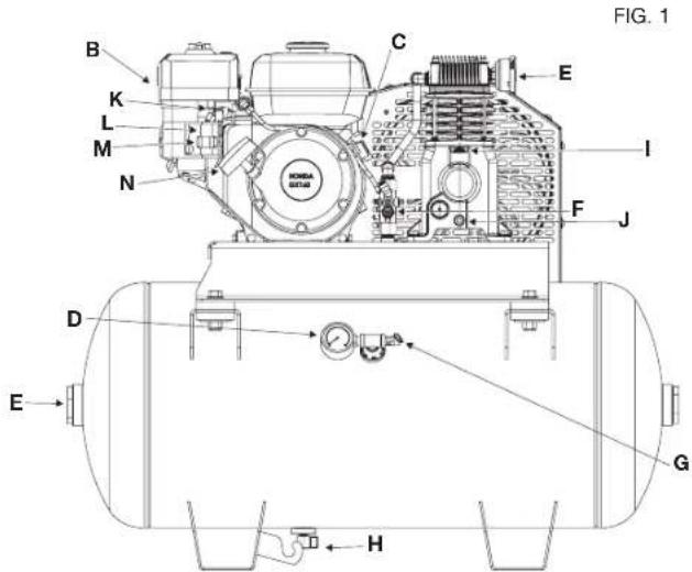
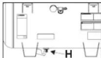
H. Air Tank Drain Valve
I. Pump Oil Fill Plug
J. Pump Oil Drain Plug
K. Fixed Throttle
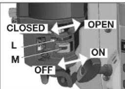
L. Choke Control
M. Fuel Valve Lever
N. Starter Grip
Pump Specifications
Inline, Vertical twin cylinder
Single Stage
Oil Lubricated
Cast iron crankcase, cylinder, and head
Weight: 49 lbs. (22.22 kg.)
Oil Capacity: 16 oz. (473 mL)
Engine Specifications
Honda 163 cc
Internal Combustion
4-stroke
High RPM 2000-3600
Specifications
| MODEL DXCMH5593011 | |
| WEIGHT | 220 lbs. (99,80 kg) |
| HEIGHT | 34.52 (876.81 mm) |
| WIDTH | 18.23" (463.04 mm) |
| MODEL DXCMH5593011 | |
| LENGTH | 39.86" (1066.8 mm) |
| AIR TANK CAPACITY | 30 gallons (113,6 liters) |
| APPROX. BLOW OFF PRESSURE | 175 psi |
Hot Surfaces
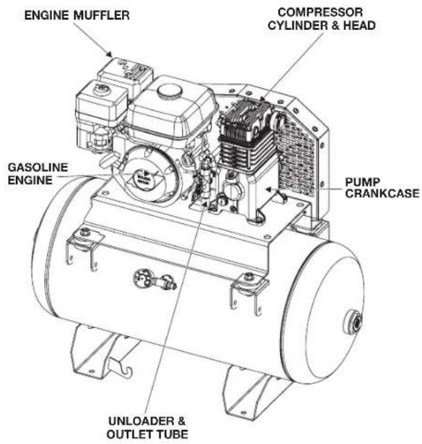
FIG. 2
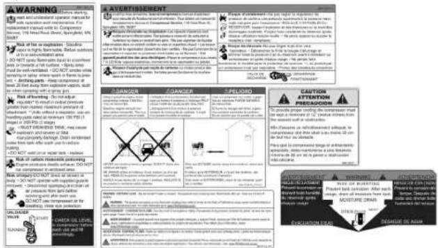
Definitions: Safety Guidelines
The definitions below describe the level of severity for each signal word. Please read the manual and pay attention to these symbols.
DANGER: Indicates an imminently hazardous situation which, if not avoided, will result in death or serious injury. WARNING: Indicates a potentially hazardous situation which, if not avoided, could result in death or serious injury. CAUTION: Indicates a potentially hazardous situation which, if not avoided, may result in minor or moderate injury.
NOTICE: Indicates a practice not related to personal injury which, if not avoided, may result in property damage.
IF YOU HAVE ANY QUESTIONS OR COMMENTS ABOUT THIS OR ANY DEWALT TOOL, CALL US TOLL FREE AT: 1-888-895-4549
Important Safety Instructions
ADANGER: Carbon Monoxide. Using an engine indoors can kill you in minutes. Engine exhaust contains high levels of carbon monoxide (CO), a poisonous gas you cannot see or smell. You may be breathing CO even if you DO NOT smell engine exhaust.
- NEVER use an engine inside homes, garages, crawlspaces, or other partly enclosed areas. Deadly levels of carbon monoxide can build up in these areas. Using a fan or opening windows and doors does NOT supply enough fresh air.
-
ONLY use outdoors and far away from open windows, doors and vents. These openings can pull in engine exhaust.
-
Even when the engine is used correctly, CO may leak into your home. ALWAYS use a battery-powered or battery backup CO alarm (not supplied) in the home. Read and follow all directions for CO alarm before using. If you start to feel sick, dizzy or weak at anytime, move to fresh air immediately. See a doctor. You could have carbon monoxide poisoning.
WARNING: Do not operate this unit until you read this instruction manual and the engine instruction manual for safety, operation and maintenance instructions.
WARNING: This product may not be equipped with a sparkarresting muffler. If the product is not equipped and will be used around flam ma ble ma terials or on land covered with materials such as agricultural crops, forest, brush, grass or other similar items, then an ap proved spark arrester must be installed and is legally required in the state of California. ItisaviolationofCaliforniastatutes section 130050 and/or sec tions 4442 and 4443 of the California Public Re sourc es Code, unless the engine is equipped with a spark arrester, as defined in section 4442, and maintained in effective working order. Spark arresters are also required on some U.S. For est Service land and may also be legally required under other statutesandordinances.
WARNING: CONTAINS LEAD. May be harmful if eaten or chewed. May generate dust containing lead. Wash hands after use. Keep out of reach of children.
WARNING: This product can expose you to chemicals including Lead, which is known to the State of California to cause cancer and birth defects or other reproductive harm. For more information go to www.P65Warnings.ca.gov.
SAVE THESE INSTRUCTIONS

DANGER: RISK OF EXPLOSION OR FIRE
WHAT CAN HAPPEN HOW TO PREVENT IT
- Spilled gas o line and it's vapors can be come ignited from cigarette sparks, electrical arcing, exhaust gas es and hot engine components such as the muffler.
- Heat will ex pand fuel in the tank which could result in spillage and pos si ble fire explosion.
- Shut off en gine and allow it to cool before adding fuel to the tank.
- Use care in filling tank to avoid spill ing fuel. Move unit away from fueling area before starting engine.
-
Keep maximum fuel level 1/2'' (12.7 mm) be low bottom of filler neck to allow for expansion.
-
Combustible materials which come into contact with hot engine parts can become ignited.
- Improperly stored fuel could lead to accident tal ignition. Fuelimproperlysecured could get into the hands of childrenorotherunqualified persons.
-
Unattended operation of this product could result in personal injury or property damage. To reduce the risk of fire, do not allow the compressor to operate unattended.
-
Add fuel outdoors in a well ventilated area. Make sure there are no sources of ignition, such as cigarettes near refueling location.
- Operate compressor in a clean, dry, well ventilated area a minimum of 48^ (1.22 m) from any building, object or wall. Do not operate unit indoors or in any confined area.
- Operate compressor in an open area away from dry brush, weeds or other combustible materials.
-
Store fuel in an OSHA-approved con tain er, in a se cure location away from work area.
-
Always remain in attendance with the product when it is operating.

DANGER: RISK TO BREATHING (ASPHYXIATION)
WHAT CAN HAPPEN HOW TO PREVENT IT
-
Breathing ex haust fumes will cause se rous injury or death! En gine exhaust containscarbonmonoxide, an odorless and deadly gas.
-
Always operate air compressor outside in a clean, well ventilated area. Avoid enclosed areas such as garages, basements, storage sheds, which lack a steady exchange or air. Keep children, pets and others away from area of operation.
-
The compressed air directly from your compressor is not safe for breathing. The air stream may contain carbon monoxide, toxic vapors, or solid particles from the air tank. Breathing these contaminants can cause serious injury or death.
-
Never use air obtained directly from the compressor to supply air for human consumption. The compressor is not equipped with suitable filters and in-line safety equipment for human consumption.
-
Exposure to chemicals in dust created by power sanding, sawing, grinding, drilling and other construction activities may be harmful.
- Sprayed materials such as paint, paint solvents, paint remover, insecticides, weed killers, may contain harmful vapors and poisons.

DANGER: RISK OF BURSTING
Air Tank: On February 26, 2002, the U.S. Consumer Product Safety Commission published Release # 02-108 concerning air compressor tank safety:
Air compressor receiver tanks do not have an infinite life. Tank life is dependent upon several factors, some of which include operating conditions, ambient conditions, proper installations, field modifications, and the level of maintenance. The exact effect of these factors on air receiver life is difficult to predict.
If proper maintenance procedures are not followed, internal corrosion to the inner wall of the air receiver tank can cause the air tank to unexpectedly rupture allowing pressurized air to suddenly and forcefully escape, posing risk of injury to consumers.
Your compressor air tank must be removed from service by the end of the year shown on your tank warning label.
The following conditions could lead to a weakening of the air tank, and result in a violent air tank explosion:
WHAT CAN HAPPEN HOW TO PREVENT IT
- Failure to properly drain condensed water from air tank, causing rust and thinning of the steel air tank.
- Modifications or attempted repairs to the air tank.
- Unauthorized modifications to the unloader valve, safety valve, or any other components which control air tank pressure.
-
Excessive vibration can weaken the air tank and cause rupture or explosion. Excessive vibration will occur if the compressor is not properly mounted or if engine operates above recommended RPM.
-
Drain air tank daily or after each use. If air tank develops a leak, replace it immediately with a new air tank or replace the entire compressor.
- Never drill into, weld or make any modifications to the air tank or its attachments. Never attempt to repair a damaged or leaking air tank. Replace with a new air tank.
The air tank is designed to withstand specific operating pressures. Never make adjustments or parts substitutions to alter the factory set operating pressures.
Attachments & Accessories:
- Exceeding the pressure rating of air tools, spray guns, air operated accessories, tires and other inflatable can cause them to explode or fly apart, and could result in serious injury.
Tires:
Over inflation of tires could result in serious injury and property damage.
-
Follow the equipment manufacturers recommendation and never exceed the maximum allowable pressure rating of attachments. Never use compressor to inflate small low pressure objects such as children's toys, footballs, basketballs, etc.
-
Use a tire pressure gauge to check the tires pressure before each use and while inflating tires; see the tire sidewall for the correct tire pressure. NOTE: Air tanks, compressors and similar equipment used to inflate tires can fill small tires very rapidly. Adjust pressure regulator on air supply to no more than the rating of the tire pressure. Add air in small increments and frequently use the tire gauge to prevent over inflation.

ADANGER: RISK OF INJURY OR PROPER TY DAMAGE WHEN TRANSPORTING OR STORING WHAT CAN HAPPEN HOW TO PREVENT IT
- Oil can leak or spill and could result in fire or breathing hazard; serious injury or death can result. Oil leaks will damage carpet, paint or other surfaces in vehicles or trailers.
Always place compressor on a protective mat when transporting to protect against damage to vehicle from leaks. Remove compressor from vehicle immediately upon arrival at your destination. Always keep compressor level and never lie on its side.

WARNING: RISK FROM FLYING OBJECTS AT CAN HAPPEN HOW TO PREVENT IT
- The compressed air stream can cause soft tissue damage to exposed skin and can propel dirt, chips, loose particles and small objects at high speed, resulting in property damage or personal injury.
Always wear certified safety equipment: ANSI Z87.1 eye protection (CAN/CSA Z94.3) with side shields when using the compressor.
- Never point any nozzle or sprayer toward any part of the body or at other people or animals.
Always turn the compressor off and bleed pressure from the air hose and air tank before attempting maintenance, attaching tools or accessories.
WARNING: RISK FROM MOVING PARTS T CAN HAPPEN HOW TO PREVENT IT
The engine can start accidentally if the flywheel is turned by hand or moved by pulling on the starter rope.
- Moving parts such as the pulley, flywheel, and belt can cause serious injury if they come into contact with you or your clothing.
Always disconnect the spark plug and bleed pressure from the air tank before performing maintenance.
- Never operate the compressor with guards or covers which are damaged or removed.
- Keep your hair, clothing and gloves away from moving parts. Loose clothes, jewelry or long hair can be caught in moving parts.
Air vents may cover moving parts and should be avoided as well.
- Any repairs required on this product should be performed by a DEWALT factory service center or a DEWALT authorized service center.

WARNING: RISK OF HOT SURFACES
WHAT CAN HAPPEN HOW TO PREVENT IT
-
Touching exposed metal such as the compressor head, engine head, engine exhaust or outlet tubes, can result in serious burns.
-
Never touch any exposed metal parts on compressor during or immediately after operation. Compressor will remain hot for several minutes after operation
- Do not reach around protective shrouds or attempt maintenance until unit has been allowed to cool.

WARNING: RISK OF UNSAFE OPERATION
WHAT CAN HAPPEN HOW TO PREVENT IT
- Unsafe op er a tion of your air compressor could lead to se risous in ju ry or death to you or others.
Review and understand all instructions and warnings in this manual.
-Becomefamiliarwiththeopera tion and con trols of the air compressor.
- Keep operating area clear of all persons, pets, and obstacles.
- Keep child dren away from the air compressor at all times.
- Do not operate the product when fatigued or under the influence of alcohol or drugs. Stay alert at all times.
- Never defeat the safety features of this product.
- Equip area of operation with a fire extinguisher.
- Do not operate machine with missing, broken, or un au thorized parts.
- Never stand on the compressor.

CAUTION: RISK FROM NOISE
WHAT CAN HAPPEN HOW TO PREVENT IT
Under some conditions and duration of use, noise from this product may contribute to hearing loss.
Always wear certified safety equipment: ANSI S12.6 (S3.19) hearing protection.
SAVE THESE INSTRUCTIONS FOR FUTURE USE
Know Your Air Compressor
READ THIS OWNER'S MANUAL AND SAFETY RULES BEFORE OPERATING YOUR UNIT. Compare the illustrations with your unit to familiarize yourself with the location of various controls and adjustments. Save this manual for future reference.
FEATURES
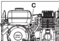
ELECTRIC START
The engine switch (C) can be placed in three positions; START, RUN and OFF. See Starting under Operation for complete starting instructions.
UNloader VALVE
When the maximum air tank pressure is obtained, the unloader valve (F) will blow-off. This will cause the compressor to exhaust the air to the atmosphere and not the tank.
Manual Lock: The manual lock allows you to manually unload the compressor with air port. To operate the manual lock: Rotate the man port to the open position to prevent air tank port. Manual lock unloader lever to the closed port engine to allow air tank pressure to build. NC port when manual lock unloader lever in the open position.
SAFETY VALVE
This valve (G) is designed to prevent system failures by relieving pressure from the system when the compressed air reaches a predeter
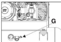
mined level. The valve is preset by the manu facturer and must not be removed or modified in any way.
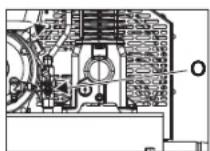
CHECK VALVE
When the air compressor is operating, the check valve (O) is open, allowing compressed air to enter the air tank. When the air compressor reaches cut-out pressure, the check valve closes, allowing air pressure to remain inside the air tank.
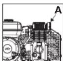
AIR INTAKE FILTER
The filter (A) is designed to clean air entering the pump. To ensure the pump continually receives a clean, cool, and dry air supply the filter must always be clean and the filter intake must be free from obstructions.
AIR TANK DRAIN VALVE
The drain valve (H) is located at the base of the air tank and is used to drain condensation at the end of each use. See Draining Air Tank under Maintenance.
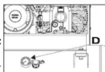
TANK PRESSUREGAUGE
The tank pressure gauge (D) indicates the reserve air pressure in the tank.
GLOBE VALVE/AIR DISCHARGE VALVE: (sold separately, not shown)
Opens and closes air distribution from compressor.
REGULATOR (sold separately, not shown):
An air pressure regulator or a separate air transformer which combines the functions of air regulation and/or moisture and dirt removal is recommended for most applications.
AIR COMPRESSOR PUMP
The pump compresses air into the air tank. Working air is not available until the compressor has raised the air tank pressure above that required at the air outlet.
GASOLINE ENGINE
The gasoline engine powers the pump. The engine drives a pulley and belt, which transfers power from the engine to the pump pistons via a flywheel and a crankshaft. The flywheel fan helps cool the pump.
THROTTLE CONTROL
When maxi mum air tank presure is reached and the unloader valve vents air, it activates the throttle control on the engine. This gas saving feature holds the engine at a factory-set idling speed until air pressure in the air tank drops to reset pressure. The unloader valve then reactivates the throttle control and accelerates the engine to full throttle.
LOW OIL SHUT DOWN SENSOR
The air compressor engine is equipped with a low oil shutdown sensor. This is a safety device designed to protect your engine from damage in the event the oil level in the crankcase is below minimum.
If the oil in the engine gets low while the air compressor is running it will automatically shut down the engine and will not restart until oil is added to the engine. If the oil is low before start-up, the engine will not start until oil is added.
NOTE: The low oil shutdown sensor is very sensitive. You must fill the engine to the full mark on the dipstick to inactivate this safety device.
INSTALLATION
Assembly (refer to Fig. 1)
Unpack the air compressor. Inspect the unit for damage. If the unit has been damaged in transit, contact the carrier and complete a damage claim. Do this immediately because there are time limitations to damage claims.
The carton should contain:
air compressor
- operator manuals
- engine manual
- vibration pads (4)
Check the compressor's serial label to ensure that you have received the model ordered, and that it has the required pressure rating for its intended use.
INSTALLING HOSES
WARNING: Risk of unsafe operation. Firmly grasp hose in hand when installing or disconnecting to prevent hose whip.
- Pull ring on safety valve allowing air to bleed from the tank until tank pressure is 0 psi. Release safety valve ring.
- Apply sealant tape to hose threads.
- Assemble hose to air outlet (E).IMPORTANT: Do not assemble splitters directly to the air outlet (E).
NOTE: Assembling quick connect bodies to air outlet and quick connect plugs to hose ends make connecting and disconnecting hoses simple and easy. Quick connect bodies and plugs are available for purchase from your local dealer or authorized service center.
DISCONNECTING HOSES
WARNING: Risk of unsafe operation. Firmly grasp hose in hand
when installing or disconnecting to prevent hose whip.
- Pull ring on safety valve allowing air to bleed from the tank until tank pressure is 0 psi. Release safety valve ring.
- Remove hose from air outlet (E).
Lubrication and Oil
ENGINE
- The engine was filled WITH oil at the manufacturer. Check engine oil level before operating unit. If necessary, fill engine to the appropriate level with recommended oil, see engine's instruction manual supplied by engine manufacturer for correct procedure.
- Add fuel to engine. See engine's instruction manual supplied by engine manufacturer for correct procedure.
WARNING: Risk of explosion or fire. Gasoline vapor is highly flammable. Refuel outdoors preferably, or only in well-ventilated areas. Do not refuel or check gasoline level while the engine is running. Do not store, spill or use gasoline near an open flame, a source of sparks (such as welding), or near operating electrical equipment.
AIR COMPRESSOR
The air compressor pump was filled WITH oil at the manufacturer. Check air compressor pump oil level before operating unit. See Compressor Pump Oil under Maintenance.
Compatibility
Air tools and accessories that are run off the compressor must be compatible with petroleum based products. If you suspect that a material is not compatible with petroleum products, an air line filter for removal of moisture and oil vapor in compressed air is required.
NOTE: Always use an air line filter to remove moisture and oil vapor
when spraying paint.
Location
WARNING: Risk of breathing. Exhaust from the gasoline engine contains deadly carbon monoxide, which is odorless and toxic. Operate engine only in well ventilated areas.
NOTICE: Risk of property damage. In order to avoid damaging the air compressor, do not allow the unit to be tilted more than 10^ when operating.
Place air compressor at least 4 ft (1.2 m) away from obstacles that may prevent proper ventilation. Keep unit away from areas that have dirt, vapor and volatile fumes in the atmosphere which may clog and gum up the intake filter and valves, causing inefficient operation.
HUMID AREAS
In frequently humid areas, moisture may form in the pump and produce sludge in the oil, causing running parts to wear out prematurely. Excessive moisture is especially likely to occur if the unit is located in an unheated area that is subject to large temperature changes. Two signs of excessive humidity are external condensation on the pump when it cools down and a "milky" appearance in compressor oil. You may be able to prevent moisture from forming in the pump by increasing ventilation or operating for longer intervals.
NOISE CONSIDERATIONS
Consult local officials for information regarding acceptable noise levels in your area. To reduce excessive noise, use vibration mounts or silencers, relocate the unit or construct total enclosures or baffle walls. Contact a DeWALT service center or call 1-888-895-4549 for assistance.
Anchoring of the Air Compressor
WARNING: Risk of bursting. Excessive vibration can weaken the air tank and cause an explosion. The compressor must be properly mounted.
The air compressor MUST be bolted to a level, solid surface.
Remove the compressor from the shipping pallet and place it on the floor or a hard, level surface. The compressor must be level to ensure proper lubrication of the pump and good drainage of the moisture in the tank.
The shipping pallet is not designed as a base for an operating compressor. Operating the compressor while it is on the pallet will void your warranty.
To prevent damage to tank and pump, the tank must be shimmmed so the pump is level within 1/8 per lineal foot maximum to distribute oil properly. Fasten to floor and NEVER force tank feet to floor without
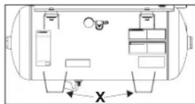
shims when tightening. We also recommend the use of vibration pads (094-0137) under tank feet (see X).
NOTE: If the compressor is mounted on a vehicle, the vehicle must be parked on a level surface while operating the compressor. This is to ensure proper lubrication of the pump and gasoline engine.
Pre-Start Checklist (refer to Fig. 1)
- Ensure engine START/RUN/OFF switch (C) is in the OFF position.
- Ensure air tank is drained, see Draining Air Tank under Maintenance.
- Ensure the drain valve (H) is closed.
- Ensure safety valve (G) is functioning properly, see Checking Safety Valve under Maintenance.
- Check pump oil level, see Compressor Pump Oil under Maintenance.
CAUTION: Do not operate without oil or with inadequate oil. DEWALT is not responsible for compressor failure caused by inadequate oil.
- Check engine's oil and fuel level, see engine's instruction manual for correct procedures.
- Visually inspect drive belt. Replace belt if frayed, cracked, or worn
NOTE: Outer belt cover must be removed to inspect drive belt.
8. Ensure all guards, covers, and labels are in place, legible (for labels) and securely mounted. Do not use compressor until all items have been verified.
WARNING: Do not operate this unit until you read this instruction manual and the engine instruction manual for safety, operation and maintenance instructions.
Break-in Procedure
NOTICE: Risk of property damage. Serious damage may result if the following break-in instructions are not closely followed.
This procedure is required:
- Before the air compressor is used for the first time.
-
When the check valve has been replaced.
-
When the compressor pump has been replaced.
The procedure:
- Follow Pre-Start Checklist.
- Rotate the unloader's manual lock to the open position to prevent air tank pressure buildup.
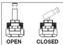
3.Prepare engine for first time use, see engine's instruction manual for correct procedure. - Place the fuel valve lever (M) in the ON position.
- If the engine is cold, move the choke (L) to the CLOSED position as shown. If the engine is hot, move the choke to the OPEN position.
6. Recoil Start:
a. Turn the engine START/RUN/OFF switch (C) to the RUN position.
b. AWARNING: Risk of unsafe operation. Pull starter grip slowly until resistance is felt. Then pull starter grip (N) rapidly to avoid kickback and prevent hand or arm injury.
NOTE: Do not allow the starter grip to snap back. Return it gently by hand.
NOTE: If the oil level in the engine is low, the engine will not start. If the engine does not start, check the oil level and add oil as needed.
NOTE: To ensure maximum oil lubrication, operate the unit on a level surface.
- As the engine warms up, move the choke to the OPEN position.
-
Run the air compressor for 30 minutes to seat the rings and lubricate all the internal surfaces. Ensure there is no pressure build up in the air tank by observing the reading on the air tank pressure gauge.
-
Rotate the manual lock on the unloader valve into the closed position so the air tank pressure can build.
- Compressed air will be available from the hose air outlet until it is used up or bled off.
OPERATING PROCEDURES
Start-up (refer to Fig. 1)
WARNING: Do not operate this unit until you read this instruction manual and the engine instruction manual for safety, operation and maintenance instructions.
- Follow Pre-Start Checklist.
- Rotate the manual lock unloader lever to the open position to assist with start up.
- Place the fuel valve lever (M) in the ON position.
- If the engine is cold, move the choke (L) to the CLOSED position as shown. If the engine is hot, move the choke to the OPEN position.
- Recoil Start:
a. Turn the engine START/RUN/OFF switch (C) to the RUN position.
b. AWARNING: Risk of unsafe operation. Pull starter grip slowly until resistance is felt. Then pull starter grip (N) rapidly to avoid kickback and prevent hand or arm injury.
NOTE: Do not allow the starter grip to snap back. Return it gently by hand.
NOTE: If the oil level in the engine is low, the engine will not start. If the engine does not start, check the oil level and add oil as needed. NOTE: To ensure maximum oil lubrication, operate the unit on a level surface.
6. As the engine warms up, move the choke to the OPEN position.
- Rotate manual lock unloader lever to the closed position to allow air tank pressure to build. NOTE: Pump will not operate with the manual lock unloader lever in the open position.
- Allow compressor to pump up to blow off pressure.
NOTE: If any unusual noise or vibration is noticed, stop the compressor and refer to the troubleshooting section.
NOTE: The air compressor pump is capable of running continuously. To prolong the air compressor's life, it is recommended to run at high throttle 50 - 75% of the run time and idle for 25% of the run time. - Attach hose and accessory.
WARNING: Risk of unsafe operation. Firmly grasp hose in hand when installing or disconnecting to prevent hose whip.
WARNING: Risk of unsafe operation. Do not use damaged or worn accessories.
CAUTION: Risk of unsafe operation. Compressed air from the unit may contain wa ter condensation and oil mist. Do not spray un fil tered air at an item that could be damaged by moisture. Some air op erated tools or de vic es may require filtered air. Read the in strc tions for the air tool or device.
Shut-down
- Place the engine START/RUN/OFF switch (C) to the OFF Position.
- Place the fuel valve lever (M) in the OFF position.
NOTE: If finished using compressor, follow Steps 3-5. - Remove hose and accessory.
- Pull ring on safety valve (G) allowing air to bleed from the tank until tank pressure is approximately 20 psi. Release safety valve ring.
- Drain the air tank. See Draining Air Tank under Maintenance.
WARNING: Risk of bursting. Drain air tank daily. Water will condense in air tank. If not drained, water will corrode and weaken the air tank causing a risk of air tank rupture.
MAINTENANCE (refer to Fig. 1)
The following procedures must be followed when maintenance or service is performed on the air compressor.
- Ensure engine START/RUN/OFF switch (C) is in the OFF position.
- Disconnect spark plug wire.
-
Drain air tank.
-
Allow air compressor to cool down before starting service
NOTE: All compressed air systems contain maintenance parts (e.g. oil, filters, separators) that are periodically replaced. These used parts may contain substances that are regulated and must be disposed of in accordance with local, state, and federal laws and regulations.
NOTE: Take note of the positions and locations of parts during disassembly to make reassembly easier.
NOTE: Any service operations not included in this section should be performed by a DEWALT factory service center or a DEWALT authorized service center.
Maintenance Chart
| Procedure | Daily | Weekly | Monthly or every 50 Hours | 1 year or 200 Hours | See tank warning label |
| Check safety valve | X | ||||
| Inspect air filter | \( X^+ \) | ||||
| Drain air tank | X | ||||
| Check pump oil level | X | ||||
| Change pump oil | X **+ | ||||
| Oil leak inspection | X | ||||
| Inspect drive belt | X | ||||
| Check drive belt tension | X | ||||
| Check pulley/flywheel alignment | X | ||||
| Check for unusual noise/vibration | X | ||||
| Check for air leaks | \( X^* \) | ||||
| Clean compressor exterior | X | ||||
| Remove tank from service | \( X^{++} \) | ||||
| Engine See engine instruction manual. | |||||
| * To check for air leaks apply a solution of soapy water around joints While compressor is pumping to pressure and after pressure cuts out, look for air bubbles to form. | |||||
| ** The pump oil must be changed after the first 20 hours or operation Thereafter, when using full synthetic non-detergent air compressor oil, change oil every 200 hours of operation or once a year, whichever comes first. | |||||
| + Perform more frequent in dusty or humid conditions. | |||||
| ** For more information, call 1-888-895-4549 . | |||||
WARNING: To avoid personal injury, always shut off the gasoline engine and relieve all air pressure from the system before performing any service on the air compressor.
To ensure efficient operation and longer life of the air compressor outfit, a routine maintenance schedule should be prepared and followed. The following routine maintenance schedule is geared to an outfit in a normal working environment operating on a daily basis. If necessary, the schedule should be modified to suit the conditions under which your compressor is used. The modifications will depend upon the hours of operation and the working environment. Compressor outfits in an extremely dirty and/or hostile environment will require a greater frequency of all maintenance checks. NOTE: See Operation section for the location of controls.
Checking Safety Valve (refer to Fig. 1)
WARNING: Hot surfaces. Risk of burn. Tubes, pump head, and surrounding parts are very hot, do not touch (see the Hot Surfaces identified in Fig. 2). Allow compressor to cool prior to servicing.
WARNING: Risk of bursting. If the safety valve does not work properly, over-pressurization may occur, causing air tank rupture or an explosion.
WARNING: Risk from flying objects. Always wear certified safety equipment: ANSI Z87.1 eye protection (CAN/CSA Z94.3) with side shields.
Before starting compressor, pull the ring on the safety valve to make sure that the safety valve operates freely. If the valve is stuck or does not operate smoothly, it must be replaced with the same type of valve.
Checking Air Filter
WARNING: Hot surfaces. Risk of burn. Tubes, pump head, and surrounding parts are very hot, do not touch (see the Hot Surfaces identified in Fig. 2). Allow compressor to cool prior to servicing.
A dirty air filter will not allow the compressor to operate at full capacity. Keep the air filter clean at all times.
-
Ensure engine START/RUN/OFF switch (C) is in the OFF position.
-
Allow unit to cool.
- Remove the outer metal cover (Q).
- Remove element (R) from filter base.
- If element needs cleaning, blow out with air. Replace if needed. Purchase replacement parts from your local dealer or authorized service center. Always use identical replacement parts.
- Place element back in filter base.
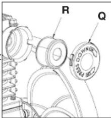
- Place the outer metal cover back over the filter element.
CAUTION: Risk of unsafe operation. Do not operate without air filter.
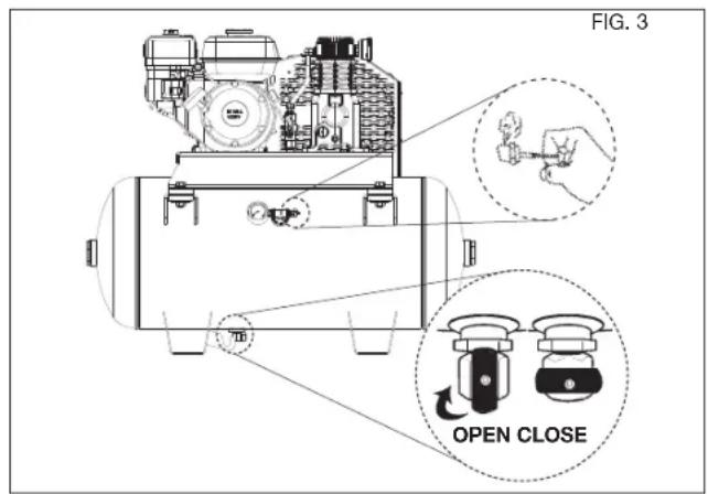
Draining Air Tank (refer to Fig. 3, pg. 17)
WARNING: Risk of unsafe operation. Air tanks contain high pressure air. Keep face and other body parts away from outlet of drain. Use eye protection [ANSI Z87.1 (CAN/CSA Z94.3)] when draining as debris can be kicked up into face.
WARNING: Risk from noise. Use ear protection (ANSI S12.6 (S3.19) as air flow noise is loud when draining.
NOTE: All compressed air systems generate condensation that accumulates in any drain point (e.g., tanks, filter, aftercoolers, dryers). This condensate contains lubricating oil and/or substances which may be regulated and must be disposed of in accordance with local, state, and federal laws and regulations.
- Ensure engine START/RUN/OFF switch (C) is in the OFF position.
- Pull ring on safety valve allowing air to bleed from the tank until tank pressure is approximately 20 psi. Release safety valve ring.
- Drain water from air tank by opening drain valve (counterclockwise) on bottom of tank.
WARNING: Risk of bursting. Water will condense in the air tank. If not drained, water will corrode and weaken the air tank causing a risk of air tank rupture.
NOTICE: Risk of property damage. Drain water from air tank may contain oil and rust which can cause stains.
- After the water has been drained, close the drain valve (clockwise).
NOTE: If drain valve is plugged, release all air pressure. The valve can then be removed, cleaned, then reinstalled.
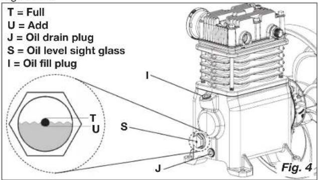
Compressor Pump Oil (refer to Fig. 4)
WARNING: Hot surfaces. Risk of burn. Tubes, pump head, and surrounding parts are very hot, do not touch (see the Hot Surfaces identified in Fig. 2). Allow compressor to cool prior to servicing.
NOTICE: Risk of property damage. Use air compressor oil only. Multi-weight automotive engine oils like 10W30 should not be used in air compressors. They leave carbon deposits on critical components, thus reducing performance and compressor life.
NOTE: Use full synthetic non-detergent air compressor oil.
NOTE: Crankcase oil capacity is approximately 53 fluid ounces (1567 ml).
Checking
- Ensure engine START/RUN/OFF switch (C) is in the OFF Position.
- The oil level should be to the middle of the sight glass (S).
- If needed remove oil fill plug (l) and slowly add oil until it reaches the middle of the sight glass.
Changing
WARNING: Hot surfaces. Risk of burn. Tubes, pump head, and surrounding parts are very hot, do not touch (see the Hot Surfaces identified in Fig. 2). Allow compressor to cool prior to servicing.
WARNING: Drain tank to release air pressure before removing the oil fill cap or oil drain plug.
- Ensure engine START/RUN/OFF switch (C) is in the OFF position.
- Allow the unit to cool.
-
Disconnect spark plug wire.
-
Drain air tank.
- Remove the oil fill plug (I).
- Remove the oil drain plug (J) and drain oil into a suitable container.
- Replace the oil drain plug (J) and tighten securely
- Slowly add compressor oil until it reaches the middle of the sight glass (S). NOTE: When filling the crankcase, the oil flows very slowly into the pump. If the oil is added too quickly, it will overflow and appear to be full.
CAUTION: Overfilling with oil will cause premature compressor failure. Do not overfill.
- Replace oil fill plug (I) and tighten securely.
- Reconnect spark plug wire.
NOTE: Pump oil contains substances that are regulated and must be disposed of in accordance with local, state and federal laws and regulations.
Belt Replacement
WARNING: To avoid personal injury, always shut off the gasoline engine and relieve all air pressure from the system before performing any service on the air compressor. Do not use the unit with the shrouds or belt guard removed. Serious injury could occur from contact with moving parts. Hot surfaces. Risk of burn. Pump head, and surrounding parts are very hot, do not touch (see the Hot Surfaces identified in Fig. 2). Allow compressor to cool prior to servicing.
- Ensure engine START/RUN/OFF switch (C) is in the OFF position.
- Allow the unit to cool.
- Disconnect spark wire.
- Drain air tank.
- Remove the front of the beltguard by removing the screws (V) using a Torx T30 bit.
-
Mark pump position on saddle.
-
Loosen the engine mounting screws and slide the engine toward the air
-
Remove the belt and replace with a new one.
- See the Adjusting Belt Tension before tightening engine mounting screws.
- Reconnect spark plug wire.
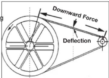
Adjusting Belt Tension
-
Ensure engine START/RUN/OFF switch (C) is in the OFF position.
-
Allow the unit to cool.
- Disconnect spark plug wire.
- Drain air tank.
- Slide engine into original position, line the engine up with the mark made earlier on saddle.
- Tighten two outside
engine mounting screws enough to hold the engine in place for checking pulley and flywheel alignment.
- The belt should deflect 1/2 (13 mm) at midway between the pulley and the flywheel when a 10 pound (4.6 kg.) weight is applied at the midway point.
- When proper belt tension 150Hz tighten all four engine mounting screws. Torque to 15-22 ft-lbs (20.3-29.8 Nm).
- Reconnect spark plug wire.
Pulley and Fly wheel Alignment
NOTE: Once the engine pulley has been moved from its factory set location, the grooves of the flywheel and pulley must be aligned to within 1/16" (1.6 mm) to prevent excessive belt wear.
The air compressor flywheel and engine pulley must be in-line (in the same plane) within 1/16 (1.6 mm) to assure belt retention within flywheel belt grooves. To check alignment, perform the following steps:
-
Ensure engine START/RUN/OFF switch (C) is in the OFF Position.
-
Allow the unit to cool.
-
Disconnect spark plug wire.
-
Drain air tank.
-
Remove belt guard.
-
Place a straightedge against the outside of the flywheel and the engine drive pulley.
-
Measure the distance between the edge of the belt and the straightedge at points
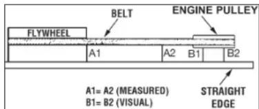
A1 and A2 in figure. The difference between measurements should be no more than 1/16" (1.6 mm).
- If the difference is greater than 1/16 (1.6 mm) loosen the set screw holding the engine drive pulley to the shaft and adjust the pulley's position on the shaft until the A1 and A2 measurements are within 1/16 (1.6 mm) of each other.
- Tighten the engine drive pulley set screw.
- Visually inspect the engine drive pulley to verify that it is perpendicular to the drive engine shaft. Points B1 and B2 of Figure should appear to be equal. If they are not, loosen the setscrew of the engine drive pulley and equalize B1 and B2, using care not to disturb the belt alignment performed in step 2.
- Retighten the engine drive pulley setscrew. Torque to 145-180in lbs (16.4-20.3 Nm).
- Reinstall belt guard.
- Reconnect spark plug wire.
Air Compressor Pump Intake and Exhaust Valves
Once a year have a Trained Service Technician check the air compressor pump intake and exhaust valves.
Inspect Air Lines and Fittings for Leaks
- Ensure engine START/RUN/OFF switch (C) is in the OFF Position.
- Allow the unit to cool.
- Disconnect spark plug wire.
- Apply a soap solution to all air line fittings and connections/piping.
- Correct any leaks found.
- Reconnect spark plug wire.
IMPORTANT: Even minor leaks can cause the air compressor to overwork, resulting in premature breakdown or inadequate performance.
Air compressor Head Bolts - Torquing
The air compressor pump head bolts should be kept properly torqued. Check the torques of the head bolts after the first five hours of operation. Torque to 32-37 ft.-lbs. (43.4-50.2 Nm).
Service and Adjustments
ALL MAINTENANCE AND REPAIR OPERATIONS NOT LISTED MUST BE PERFORMED BY TRAINED SERVICE TECHNICIAN.
WARNING: To avoid personal injury, always shut off the gasoline engine and relieve all air pressure from the system before performing any service on the air compressor. Do not use the
unit with the shrouds or belt guard removed. Serious injury could occur from contact with moving parts. Hot surfaces. Risk of burn. Pump head, and surrounding parts are very hot, do not touch (see the Hot Surfaces identified in Fig. 2). Allow compressor to cool prior to servicing.
Additional Service
Disassembly or service of the air compressor beyond what is covered in this manual is not recommended. If additional service is required, contact your nearest Authorized Warranty Service Center.
Accessories
Recommended accessories for use with your tool are available for purchase from your local dealer or authorized service center. If you need assistance in locating any accessory for your tool, please call 1-888-895-4549 or visit our website www.dewalt.com.
WARNING: The use of any other accessory not recommended for use with this tool could be hazardous. Use only accessories rated equal to or higher than the rating of the air compressor.
Service Information
Please have the following information available for all service calls: Model Number Serial Number Date and Place of Purchase
Repairs
To assure product SAFETY and RELIABILITY, repairs, maintenance and adjustment should be performed by a DEWALT factory service center, a DEWALT authorized service center or other qualified service personnel. Always use identical replacement parts.
Limited Warranty
The Manufacturer warrants from the date of purchase.
2 Year - Limited warranty on oil-lubricated air compressor pumps.
1 Year - Limited warranty on all other air compressor components. This warranty is not transferable to subsequent owners.
The Manufacturer will repair or replace, without charge, at their option, any defects due to faulty materials or workmanship. For further detail of warranty coverage and warranty repair information, call 1-(888)-895-4549 or visit dewalt.com. This warranty does not apply to accessories or damage caused where repairs have been made or attempted by others. This warranty also does not apply to merchandise sold by the Manufacturer which has been manufactured by and identified as the product of another company, such as gasoline engines. Such manufacturer's warranty, if any, will apply. ANY INCIDENTAL, INDIRECT OR CONSEQUENTIAL LOSS, DAMAGE OR EXPENSE THAT MAY RESULT FROM ANY DEFECT, FAILURE OR MALFUNCTION OF THE PRODUCT IS NOT COVERED BY THIS WARRANTY. Some states do not allow the exclusion of limitation of incidental or consequential damages, so the above limitation or exclusion may not apply to you. IMPLIED WARRANTY, INCLUDING THOSE OF MERCHANTABILITY OR FITNESS FOR A PARTICULAR PURPOSE, ARE LIMITED TO ONE YEAR FROM THE DATE OF ORIGINAL PURCHASE. Some states do not allow limitations on how long an implied warranty lasts, so the above limitations may not apply to you What the Manufacturer Will Do: (the Manufacturer) will cover parts and labor to remedy substantial defects due to materials and workmanship during the first year of ownership, with the
exceeds noted below. Parts used in repair of whole goods or accessories are warranted for the balance of the original warranty period.
What is not covered Under This Warranty? Failures by the original retail purchaser to install, maintain, and operate said equipment in accordance with standard industry practices. Modifications to the product, or tampering with components, or failure to comply with the specific recommendations of the Manufacturer set forth in the owner's manual, will render this warranty null and void. The Manufacturer shall not be liable for any repairs, replacements, or adjustments to the equipment, or any costs for labor performed by the purchaser without the Company's prior written approval. The effects of corrosion, erosion, surrounding environmental conditions, cosmetic defects, and routine maintenance items, are specifically excluded from this
warranty. Routine maintenance items such as: oil, lubricants, and air filters, as well as changing oil, air filters, belt tensioning, etc... fall under the owner's responsibility. Additional exclusions include:
freight damage, failures resulting from neglect, accident, or abuse, induction motors when operated from a generator, oil leaks, air leaks, oil consumption, leaky fittings, hoses, drain valve, bleeder tubes, and transfer tubes.
- The following components are considered normal wear items and are not covered after the first year of ownership: Belts, pulleys, flywheels, check valves, pressure switches, air unloader, throttle controls, electric motors, brushes, regulators, o-rings, pressure gauges, tubing, piping, fittings, fasteners, wheels, quick couplers, gaskets, seals, air filter housings, piston rings,
connecting rods, and piston seals.
- Labor, service calls, and travel charges, are not covered after the first year of ownership on stationary compressors (compressors without handles, or wheels). Repairs requiring overtime, weekend rates, or any other charges beyond the standard shop labor rate are not covered.
- Time required for orientation training for the service center to gain access to the product, or additional time due to inadequate egress.
- Damage caused by incorrect voltage, improperly wired, or failure to have a certified licensed electrician install the compressor, will render this warranty null and void.
- Damage caused from inadequate filter maintenance.
- Pump wear or valve damage caused by using oil not specified.
- Pump wear or damage caused by any oil contamination.
- Pump wear or valve damage caused by failure to follow proper maintenance guidelines.
Operation below proper oil level or operation without oil.
Gas Engines, if product is equipped with a gas engine, see engine manual for specific engine manufacturer's warranty coverage.
Parts purchased separately: The warranty for parts purchased separately such as: pumps, motors, etc., are as follows: From Date of Purchase
All single & two stage pumps 1 year
Electric motors 90 days
Universal motor/pump 30 days
All other parts 30 days
- No return authorization will be issued for electrical
components once items are installed.
How do You Get Service? In order to be eligible for service under this warranty you must be the original retail purchaser, and provide proof of purchase from one of the Manufacturer's dealers, distributors, or retail outlet stores. Portable compressors or components must be delivered, or shipped, to the nearest Authorized Service Center. All associated freight costs and travel charges must be borne by the consumer. Please call our toll free number 1-888-895-4549 for assistance. THIS WARRANTY GIVES YOU SPECIFIC LEGAL RIGHTS, AND YOU MAY ALSO HAVE OTHER RIGHTS WHICH VARY FROM STATE TO STATE.
THE MANUFACTURER MAKES NO OTHER WARRANTY OR REPRESENTATION OF ANY KIND WHATS EVER, EXPRESSED OR IMPLIED, EXCEPT THAT OF TITLE. ALL IMPLIED WARRANTY, INCLUDING ANY WARRANTY OF ERCHANTABILITY AND FITNESS FOR PARTICULAR PURPOSE ARE HEREBY DISCLAIMED. LIABILITY FOR CONSEQUENTIAL AND INCIDENTAL DAMAGES UNDER ANY AND ALL WARRANTY, OTHER CONTRACTS, NEGLEGENCE, OR OTHER TORTS IS EXCLUDING TO THE EXTENT EXCLUSION IS PERMITTED BY LAW.
Troubleshooting Guide
This section provides a list of the more frequently encountered malfunctions, their causes and corrective actions. The operator or maintenance personnel can perform some corrective actions, and others may require the assistance of a qualified DeWALT technician or your dealer.
Excessive air tank pressure-safety valve pops off . . . . . . 1
Air leaks 2
Continuous air leak at unloader valve. 3
Air leaks in air tank or at air tank welds. 4
Air leaks between head and valve plate. 5
Air leaks from safety valve 6
Compressor is not supplying enough air to operate accessories. 2, 7, 8, 9, 10, 12, 13
Restricted air intake. 12
Excessive vibration. 14, 15
Knocking Noise 13, 14, 15, 16, 17, 18, 19
Excessive belt wear. 13,14,16,19,20
Squealing sound. 13
Engine will not run 22, 24, 30
Moisture in pump crankcase . 5, 11, 23, 24, 25, 26, 27, 28
Pump will not run 29
Air tank pressure will not build. 29
NOTES
Troubleshooting Codes
| CODE POSSIBLE CAUSE POSSIBLE SOLUTION | ||
| 1 Unloader valve does not release pressure when air tank reaches blow-off pressure | Unloader valve must be replaced. Contact a DeWALT factory ser-vice center or a DeWALT authorized service center. | |
| 2 | Fittings are not tight | Tighten fittings where air can be heard escaping. Check fittings with soapy water solution. DO NOT OVERTIGHTEN. |
| 3 Defective unloader valve | Turn off engine, rotate manual lock unloader lever to the closed perpendicular position. If air leaks out of air tank through unloader valve, replace unloader valve. | |
| 4 Defective air tank Air tank must be replaced. Do not repair | the leak. ▲WARNING: Risk of bursting. Do not drill into, weld or otherwise modify air tank or it will weaken. The air tank can rupture or explode. | |
| 5 Leaking seals Contact a D | EWALT factory service center or a DeWALT authorized service center. | |
| 6 | Defective safety valve | Operate safety valve manually by pulling on ring. If valve still leaks, it must be replaced. |
| 7 Prolonged excessive use of air Decrease amount of air usage | ||
| 8 | Compressor is not large enough for accessory | Check the accessory air requirement. If it is higher than the SCFM or pressure supplied by your air compressor, a larger compressor is needed to operate accessory. |
| 9 Hole in air hose Check and replace air hose, if required. | ||
| 10 Unloader valve restricted Remove, clean or replace. | ||
| 11 | Unit operating in damp or humid conditions | Move unit to a dry well ventilated area. |
| 12 Restricted air intake filter Clean or replace air intake filter. | ||
| 13 Loose belt | Check belt tension, see Adjusting Belt Tension under Maintenance. | |
| 14 | Engine mounting bolts are loose | Tighten mounting screws. Torque engine mounting bolts to 15-22 ft-lbs (20.3-29.8 Nm).▲WARNING: Risk of bursting. Excessive vibration could weaken the air tank and cause it to rupture or explode. Mounting screws must be kept tightened. |
| 15 | Pump stabilizer bracket bolts are loose | Check bolt and tighten if required. Torque pump stabilizer bracket bolt to 15-22 ft-lbs (20.3-29.8 Nm).▲WARNING: Risk of bursting. Excessive vibration could weaken the air tank and cause it to rupture or explode. Stabilizer bracket bolt must be kept tightened. Never operate the unit unless equipped with the stabilizer bracket. |
| 16 | Loose pulley Tighten pulley set screw, torque to 145-180 in.-lbs. (16.4-20.3 Nm). | |
| 17 | Loose flywheel | Tighten flywheel screw, torque to 15-18 ft.-lbs. (20.3-24.4 Nm). |
| 18 | Carbon build-up in pump Contact a D | eWALT factory service center or a DeWALT authorized service center. |
| 19 | Belt to tight | Check belt tension, see Adjusting Belt Tension under Maintenance. |
| 20 | Pulley misalignment | See Motor Pulley/Flywheel Alignment under Maintenance. |
| 21 | Engine problem Contact a D | eWALT factory service center or a DeWALT authorized service center. |
| 22 | Engine or pump oil is low | Add DEWALT synthetic compressor oil to pump. See Compressor Pump Oil under Maintenance. |
| 23 | Detergent type oil being used in pump | Drain oil and refill pump with full synthetic non-detergent air compressor oil. |
| 24 | Extremely light duty cycles Run unit for longer duty cycles. It is recommended to run at high throttle 50-75% of the run time and idle for 25% of the run time. | |
| 25 | Piston rings damaged or worn Contact a D | E WALT factory service center or a DEWALT authorized service center. |
| 26 | Cylinder or piston damaged or worn Contact a D | E WALT factory service center or a DEWALT authorized service center. |
| 27 | Compressor cylinder finish worn Contact a D | E WALT factory service center or a DEWALT authorized service center. |
| 28 | Water in pump oil | Drain oil and refill pump with full synthetic non-detergent air compressor oil. |
| 29 | Manual lock unloader lever in open position | Rotate manual lock unloader lever to the closed perpendicular position. |
| 30 | Engine fuel tank empty | Add gasoline, see engine's instruction manual for correct procedure. |

FREE WARNING LABEL REPLACEMENT: If your warning labels become illegible or are missing, call 1-888-895-4549 for a free replacement.
GLOSSARY
CFM: Cubic feet per minute.
SCFM: Standard cubic feet per minute; a unit of measure of air delivery.
PSI: Pounds per square inch; a unit of measure of pressure.
Code Certification: Products that bear one or more of the following marks: UL*, CUL, ETL*, CETL, have been evaluated by OSHA certified independent safety laboratories and meet the applicable Standards for Safety.
*UL® is a registered trademark of Underwriters Laboratories and ETL® is a registered trademark of Electrical Testing Laboratories.
California Code: Unit may comply with California Code 462 (I) (2)/ (M) (2). Specification/model label is on the side of the air tank on units that comply with California Code.
Unloader Blow-Off Pressure: All models are continuous running units controlled by air tank pressure. When the maximum air tank pressure is obtained, the unloader valve will blow-off. This will cause the compressor to exhaust the air to the atmosphere and not the tank. This decreases the load on the engine and allows it to run at a near no-load condition.
Unloader Reset Pressure: When the air tank pressure drops to a predetermined point, the unloader valve closes. The air tank pressure will now increase until it reaches the unloader blow-off pressure.
Compresseur d'air
ADANGER:RISQUE D'EXPLOSION OU D'INCENDIE
CE QUI PEUT SE PRODUIRE COMMENT L'EVITER
REEMPLACEMENT Gratisuit DES ETIQUETTES
Vibrations excessives 14, 15
Cliqueis. 13, 14, 15, 16, 17, 18, 19
Usure excessive de la courroie 13, 14, 16, 19, 20
Sifflement. 13
For product, service or warranty information contact us at:
Under license from DEWALT Industrial Tool Co.
Bojo licencia de DEWALT Industrial Tool Co.
Sous licence de DEWALT Industrial Tool Co.
The following are trademarks for one or more DEWALT power tools: thee yellow and black color scheme; the "D" shaped air intake grill; the array of pyramids on the handgrip; the kit box configuration; and the array of lozenge shape humps on the surface of the tool.