
New Breeze Eco - Air Conditioning Klarstein - Free user manual and instructions
Find the device manual for free New Breeze Eco Klarstein in PDF.

| Brand | Klarstein |
| Model | New Breeze Eco |
| Product type | Mobile monoblock air conditioner |
| Cooling capacity | 10,000 BTU/h (2.9 kW) |
| Recommended area | 29 - 49 m² |
| Power supply | 220-240 V ~ 50/60 Hz |
| Power consumption (cooling) | 0.9 kW |
| Energy efficiency ratio (EER) | 3.1 |
| Noise level | 64 dB(A) |
| Refrigerant | R290 (flammable, GWP=3) |
| Operating modes | Cooling, dehumidification, fan only |
| Fan speeds | Low, medium, high, auto |
| Timer | Yes (0.5 h to 24 h) |
| Remote control | Yes (with LCD screen and turbo, night, etc. functions) |
| Night mode | Yes (gradual temperature increase) |
| Turbo function | Yes (rapid cooling) |
| Drainage | Manual or continuous via central drain |
| Filter cleaning | Removable filter washable with soapy water |
| Safety | Overload protection, automatic shutdown when tank full (error code H8) |
| Included accessories | Exhaust hose, fittings, adapter, remote control, batteries, manual |
| Repairability | Service only by certified professional (R290 circuit) |
Frequently Asked Questions - New Breeze Eco Klarstein
User questions about New Breeze Eco Klarstein
0 question about this device. Answer the ones you know or ask your own.
Ask a new question about this device
Download the instructions for your Air Conditioning in PDF format for free! Find your manual New Breeze Eco - Klarstein and take your electronic device back in hand. On this page are published all the documents necessary for the use of your device. New Breeze Eco by Klarstein.
USER MANUAL New Breeze Eco Klarstein
INHALTSVERZEICHNIS

flowchart
graph TD
    A["kemo display"] --> B["House"]
    B --> C["House"]
    C --> D["House"]
    D --> E["House"]
    E --> F["House"]
    F --> G["House"]
    G --> H["House"]
    H --> I["House"]
    I --> J["House"]
    J --> K["House"]
    K --> L["House"]
    L --> M["House"]
    M --> N["House"]
    N --> O["House"]
    O --> P["House"]
    P --> Q["House"]
    Q --> R["House"]
    R --> S["House"]
    S --> T["House"]
    T --> U["House"]
    U --> V["House"]
    V --> W["House"]
    W --> X["House"]
    X --> Y["House"]
    Y --> Z["House"]
natural_image
Technical line drawing of an industrial air conditioning unit with cooling fans and heat exchangers (no text or symbols)natural_image
Symbol of a trash bin crossed with a diagonal line, no text or numbers presentBerlin Brands Group UK Limited
PO Box 42
272 Kensington High Street
London, W8 6ND
United Kingdom
Dear Customer,
Congratulations on purchasing this device. Please read the following instructions carefully and follow them to prevent possible damages. We assume no liability for damage caused by disregard of the instructions and improper use. Scan the QR code to get access to the latest user manual and more product information.

CONTENT
Safety Instructions 30
Device Overview 32
Control Panel and Key Functions 33
Remote Control and Indicators 34
Installation 40
Cleaning and Care 45
Troubleshooting 47
Error Codes 48
Notes on Refrigerant R290 49
Product Data Sheet 50
Disposal Considerations 52
Manufacturer & Importer (UK) 52
TECHNICAL DATA
| Item number 10032511, 10033584 | |
| Power supply 220-240 V ~ 50/60 Hz | |
| Cooling capacity 10.000 BTU | |
| Room size 29 - 49 m^2 |
SAFETY INSTRUCTIONS
Special notes
- Only use agents recommended by the manufacturer for defrosting or cleaning.
- Never store the appliance in a room in which there are permanent sources of ignition (e.g. open flames, a switched on gas appliance or a switched on electric heater).
- Do not puncture or burn the appliance.
• Note that coolant may be odourless.
Note: Only use the unit in rooms larger than X m ^2 (see table):
| Model X ( m^2 ) | |
| 5000 BTU/h, 7000 BTU/h, 8000 BTU/h 4 m^2 | |
| 9000 BTU/h, 10000 BTU/h, 10500 BTU/h 12 m^2 | |
| 12000 BTU/h, 14000 BTU/h, 16000 BTU/h,18000 BTU/h 15 m^2 |
General safety instructions
• The device is only suitable for indoor use.
- Do not use the product if it needs to be repaired or if it has not been installed properly.
- Do not use the product in the following areas:
- near heat sources,
- in areas where oil can splash,
- in areas exposed to direct sunlight,
- in areas where splash water can occur,
-
near bathtubs, in washrooms, near showers or swimming pools.
-
Never insert your fingers or other objects into the ventilation openings. In particular, warn children of the dangers this may cause.
- Ensure that the unit is held vertically during transport and storage so that the compressor is correctly positioned.
• Always turn off the appliance before cleaning and unplug it from the wall outlet. - Switch off the appliance before moving it and unplug it from the wall outlet. Move the appliance slowly and carefully.
• To avoid the risk of fire, do not cover the unit.
- All fan connections must comply with local electrical safety regulations. If necessary, refer to these regulations.
• Supervise children so that they do not play with the unit.
- If the power cord is damaged, it must be replaced by the manufacturer, customer service or a similarly qualified person to avoid danger.
- This equipment may be used by children over the age of 8 and by persons (including children) with limited physical, sensory or mental capabilities and/or lack of experience and knowledge, provided they have been instructed in the use of this equipment by a person responsible for their safety and understand the hazards associated with the use of this equipment. Cleaning and maintenance of the appliance may only be carried out by children under supervision.
- The appliance must be installed in accordance with national wiring regulations.
• Type and voltage of fuses: T, 250 V AC, 2 A or higher.
- Contact customer service for cleaning and maintenance.
- Do not pull the power cord, deform or modify it, or immerse it in water. Incorrect handling of the power cord may result in damage to the equipment and/or electric shock.
• National gas regulations must be observed.
- Do not block the ventilation openings.
- Do not operate the appliance solely by inserting or removing the power plug, as this may result in electric shock or fire due to heat.
- Immediately unplug the appliance from the wall outlet if it emits strange noises, odours or smoke.
Instructions for Handling Damage
- In case of damage to the device, contact the manufacturer, customer service or a similarly qualified person.
- If damage occurs, turn off the power, unplug the power cord, and contact the manufacturer, the service representative, or a similarly qualified person.
• The power cord must be securely earthed. - If the power cord is damaged, turn off the power to avoid danger and unplug the power cord from the wall outlet. The power cord must be replaced by the manufacturer, customer service or a similarly qualified person.

WARNING
Risk of injury! Repairs to the coolant circuit may only be carried out by trained specialist personnel. Never attempt to repair the unit yourself!
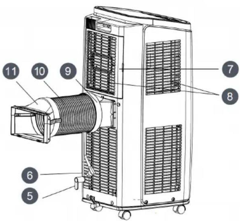
DEVICE OVERVIEW
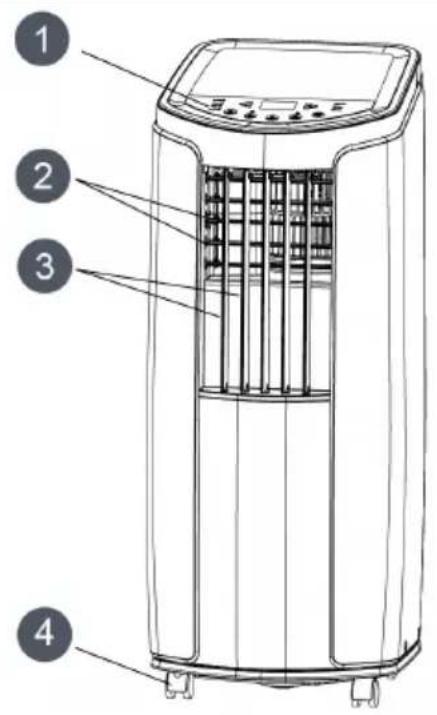
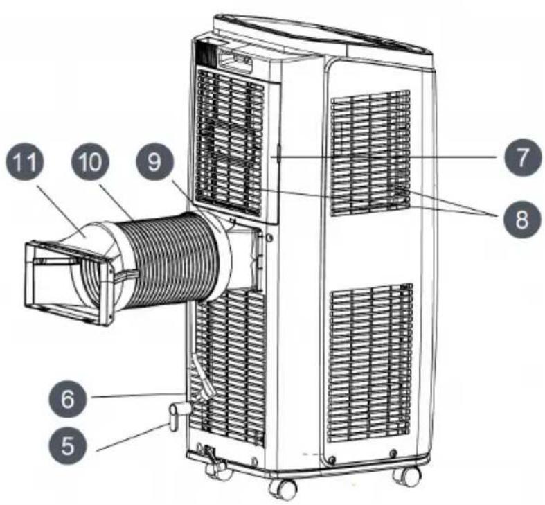
| 1 | Control panel | 7 | Ventilation slots |
| 2 | Ventilation slats | 8 | Air intake |
| 3 | Vibrating fins | 9 | Connection A |
| 4 | Rollers | 10 | Exhaust air hose |
| 5 | Cable holders | 11 | Connections B and C |
| 6 | Plugs and power cord |
CONTROL PANEL AND KEY FUNCTIONS
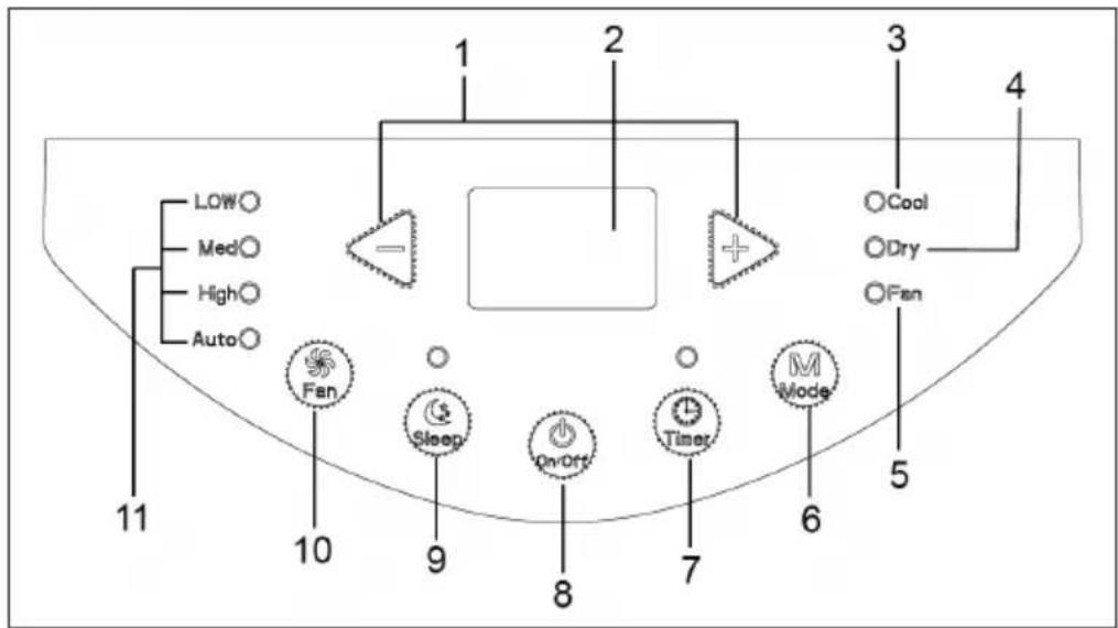
1 +/- Key
2 Temperature display
3 Cooling display
4 Drying indicator
5 Fan display
6 Mode
7 Timer
8 On / off button
9 Sleep mode
10 Fan
11 Fan speed
| +/- | In cooling mode, press these buttons to adjust the temperature in 1 °C increments. The adjustable temperature range is between 16 °C - 30 °C. This button is inactive in auto, drying or fan mode. |
| MODE | Press this button to select the mode in the following order: Cooling> Drying> Fan. |
| COOL: The cooling indicator lights up in this mode. This display shows the set temperature. The adjustable temperature is between 16 °C and 32 °C. | |
| DRY: The drying indicator lights up in this mode. This display shows no temperature. | |
| FAN: On this mode only the fan works. The fan indicator lights. The display shows no temperature. | |
| FAN | Press this button to select the speed in the following order: low > medium > high > auto > low. |
| TIMER | Press this button to call up the timer. Then press the +/- key to set the timer. Each time the button is pressed, the time will change by 0.5 hours until 10 hours are reached. After that, the value will change by 1 hour each time you press the button. After you have entered the desired value, wait 5 seconds until the display automatically accepts the time. As soon as the timer starts running, the timer indicator will light up in the display. If you want to cancel the timer, press the timer button again in timer mode. |
| SLEEP | Press this button to activate sleep mode. If the device is currently in cooling mode, the temperature will increase by 1 °C over the course of one hour as soon as the sleep mode starts. Over the next 2 hours, the temperature will rise by a further 2 °C and then will stay at this level. The sleep function does not work in fan, auto or drying mode. |
REMOTE CONTROL AND INDICATORS
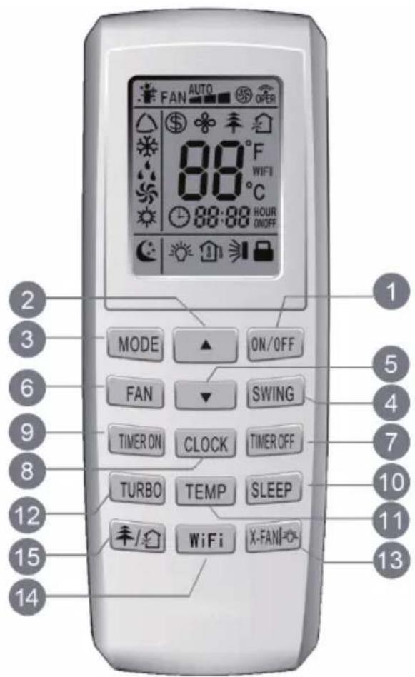
| 1 | Power button | 9 | Automatic switch-on |
| 2 | Up key (+) | 10 | Sleep mode |
| 3 | Mode | 11 | Temperature |
| 4 | Swivel movement (up/down) | 12 | Turbo |
| 5 | Down key (-) | 13 | X-Fan / Light |
| 6 | Fan | 14 | WiFi |
| 7 | Automatic switch-off | 15 | Health mode / Air purge |
| 8 | Time |
Indicators of the remote control
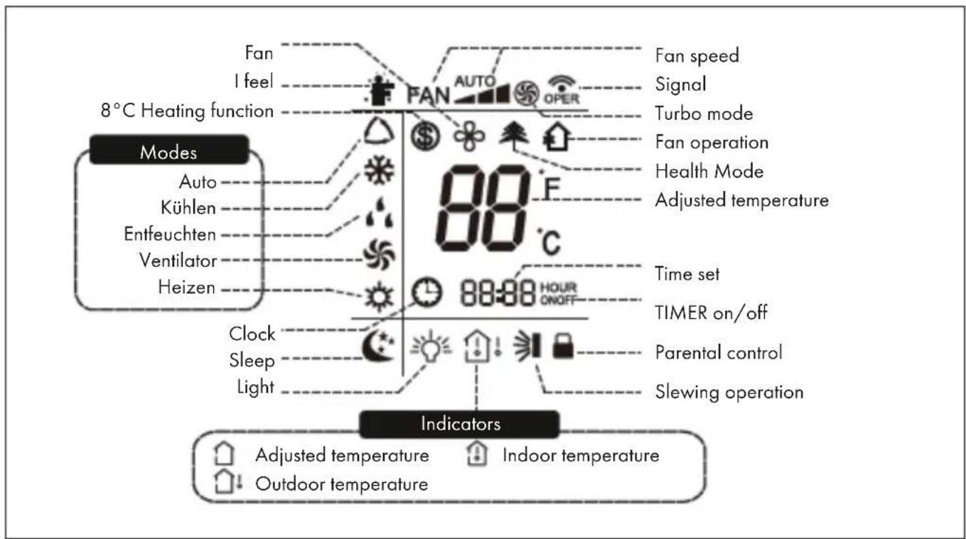
Notes:
- This is a universal remote control for air conditioning systems with multiple functions. If you press a button with functions that the device does not have, the device will remain in its current state.
- After the device is connected, the air conditioner will emit a sound and the operating light will light up red. You may now operate the device using the remote control.
- If the device is switched on, the transmit symbol 📤 on the remote control will flashe once after each key press.
- When the device is switched off, the set temperature will appear on the remote control. When switched on, the remote control display will show the symbol for starting up.
1 On/Off switch (ON/OFF)
- Press to switch the unit on or off.
- After starting, the light turns green. (The color of the indicator differs from model to model).
2 Up Button (+)
Press this button to increase the set temperature by 1 °C. Press and hold for more than 2 seconds to increase the set temperature faster. The temperature cannot be set in automatic mode.
3 Mode (MODE)
A mode is selected with each keystroke. The modes go through in the following order: AUTO > COOL > DRY > FAN > HEAT (for models with heating function).
After switching on, the automatic mode (AUTO) is selected by default. In automatic mode, the set temperature is not displayed. The appliance selects the appropriate mode depending on the room temperature to create a pleasant indoor climate. In cooling mode, nothing happens if signals are coming from the remote control.
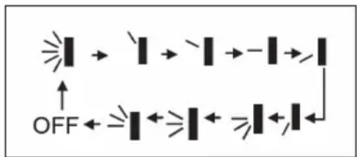
4 Pivoting movement (SWING)
Swivel movement up/down. The settings appear in the following order:
flowchart
graph TD
    A["Light Rays"] --> B["Light Rays"]
    B --> C["Light Rays"]
    C --> D["Light Rays"]
    D --> E["Light Rays"]
    E --> F["Light Rays"]
    F --> G["Light Rays"]
    G --> H["Light Rays"]
    H --> I["Light Rays"]
    I --> J["Light Rays"]
    J --> K["Light Rays"]
    K --> L["Light Rays"]
    L --> M["Light Rays"]
    M --> N["Light Rays"]
    N --> O["Light Rays"]
    O --> P["Light Rays"]
    P --> Q["Light Rays"]
    Q --> R["Light Rays"]
    R --> S["Light Rays"]
    S --> T["Light Rays"]
    T --> U["Light Rays"]
    U --> V["Light Rays"]
    V --> W["Light Rays"]
    W --> X["Light Rays"]
    X --> Y["Light Rays"]
    Y --> Z["Light Rays"]
This is a universal remote control. When the ≥slant / is sent, the device will understand the input as follows:
5 Down button (-)
Use this button to reduce the set temperature by 1 °C . Press and hold the button for more than 2 seconds to reduce the set temperature faster. The temperature cannot be set in automatic mode.
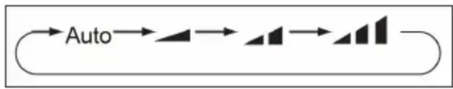
6 Fan (FAN)
Press to set the fan speed in a circle: Automatic, low, medium, high.
flowchart
graph LR
    A["Auto"] --> B["Step 1"]
    B --> C["Step 2"]
    C --> D["Step 3"]
    D --> E["Step 4"]
7 Automatic switch-off (TIMER OFF)
Press this button to activate the automatic switch-off function. To deactivate the auto power off, simply press the button again. The setting is made in the same way as for automatic switch-on.
8 Setting the time (CLOCK)
Setting the time: Press the CLOCK button, the clock symbol flashes. Press the [+] or [-] button within 5 seconds to set the current time. Press and hold one of the buttons for at least 2 seconds, the set time increases or decreases by 1 or 10 minutes every half second. If the display flashes after setting, press CLOCK again and the time is displayed continuously.
9 Automatic power on (TIMER ON)
Press this button to set the automatic switch-on. To turn off the auto power on, press the button again.
After pressing the button, the clock symbol on the display disappears. Within 5 seconds, press the [+] or [-] button to set the power on time. Press [+] and [-] to increase or decrease the time by 1 minute. Press and hold any of the buttons for at least 2 seconds to increase or decrease the set time by 1 or 10 minutes every half second.
Press to switch the sleep mode on or off. This function is available in heating or cooling mode and provides the most comfortable temperature for you.
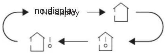
9 TEMP / Temperature setting
Press this button to show the set temperature, indoor temperature or outdoor temperature on the display.
flowchart
graph TD
    A["no display"] --> B["House"]
    B --> C["House"]
    C --> D["House"]
    D --> E["House"]
    E --> F["House"]
    F --> G["House"]
    G --> H["House"]
    H --> I["House"]
    I --> J["House"]
    J --> K["House"]
    K --> L["House"]
    L --> M["House"]
    M --> N["House"]
    N --> O["House"]
    O --> P["House"]
    P --> Q["House"]
    Q --> R["House"]
    R --> S["House"]
    S --> T["House"]
    T --> U["House"]
    U --> V["House"]
    V --> W["House"]
    W --> X["House"]
    X --> Y["House"]
    Y --> Z["House"]
    Z --> A
- Selection of ⬆ on the remote control: display of the set temperature.
- Selection of 📁 on the remote control: display of the internal temperature.
- Selection of 🖼️ on the remote control: display of the outside temperature.
Note: On some models, the outside temperature cannot be displayed. Display only for models with a two-digit display.
12 TURBO
Pressing this button turns the turbo on or off. The appliance reaches the set temperature in the fastest way. In cooling or heating mode, the fan blows at high speed.
13 Ventilation mode (X-FAN)
After pressing this button in cooling mode and dehumidifying mode, the display shows ✿ and the fan runs for 2 minutes to dry the indoor unit. Once the unit is switched on, ventilation mode is automatically activated. The function is not available in automatic mode, ventilation mode and heating mode.
14 Light
Use this button to turn off the light of the remote control display. The light symbol disappears. Press the button again to switch the light back on. The light symbol appears again.
15 WiFi (wireless)
Turn WiFi on and off. When WiFi is on, the WiFi icon appears on the remote control display. When the power is off, press and hold the MODE and WiFi buttons simultaneously for 1 second to restore the WLAN module to its factory default settings.
16 Health mode - Air cleaning (¥)
Switching the health mode and air purge on and off during operation.
- Press 1x: Starting the air purge. The display shows
- Press 2x: Starting the health mode and the air purge function simultaneously. The display shows and .
- Press 3x: Switch off both functions.
- Press 4x: Start of the health function. The display shows ± . These functions are available on some models.
Parental lock
Press [+] and [-] simultaneously to turn on the parental lock. When the parental lock is on, the screen appears on the remote control. If you now press buttons, the symbol flashes three times and the remote control does not send a signal.
Setting the temperature in °F or °C
With the instrument switched off, press the MODE and „-” buttons simultaneously to switch between the display in °C and °F.
Energy saving function
In cooling mode, press TEMP and CLOCK simultaneously to enter energy saving mode. The display on the unit shows „SE“. Press the buttons again to exit the mode.
INSTALLATION
Accessory
 joint A joint A | 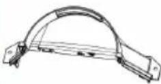 joint B joint B | 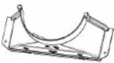 joint C joint C | 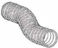 heat discharge pipe heat discharge pipe | 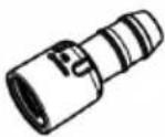 Adapter (1) Adapter (1) | ||||
 wire hook (2) wire hook (2) |  screw(3) screw(3) |  pipe clip pipe clip | 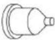 rubber plug rubber plug | 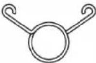 pipe hoop (2) pipe hoop (2) | ||||
 drainage pipe drainage pipe | 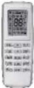 remote controller remote controller |  battery (2)(AAA 1.5V) battery (2)(AAA 1.5V) |  user's manual user's manual | |||||
Additionally you need: a cross screwdriver, a straight screwdriver, a saw, a gauge, a scissor and a pencil.
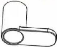
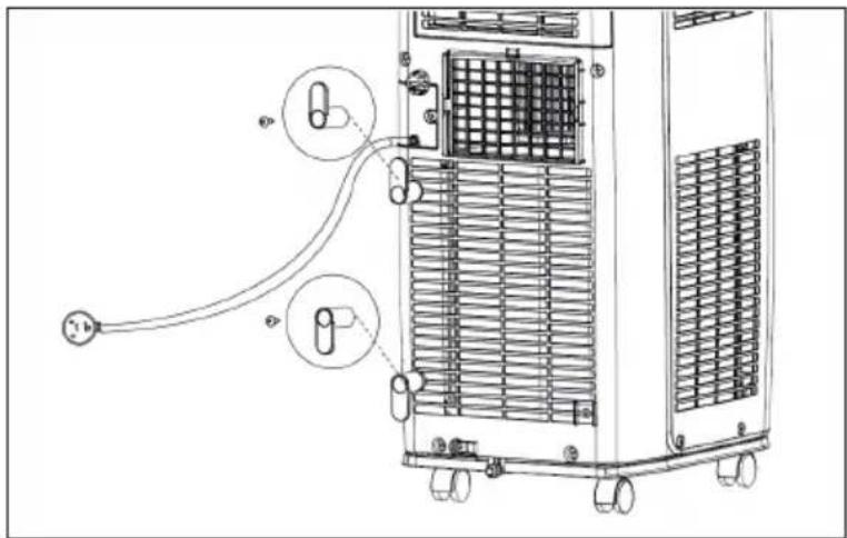
Installing the Wire Hook
- Assemble the wire hook at the back of the unit with screws (the direction of wire hook is as shown in the following fig.
• Wind the power cord around the wire hook.
natural_image
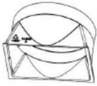
Technical diagram of an air conditioning unit with labeled components and wiring (no text or symbols present)Installing the Heat Discharge Pipe
- Rotate joint A and joint B clockwise into the two ends of heat discharge pipe.
- Insert joint A of heat discharge pipe (the side with „TOP“ is upwards) into the groove until you hear a sound.
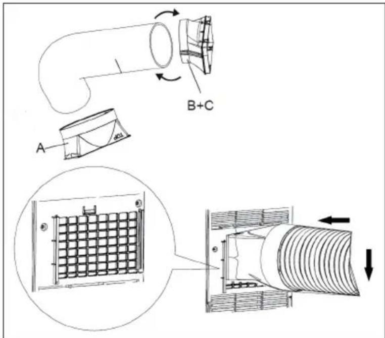
-
Aim the locating pole of joint B of heat discharge pipe at the opening of joint C; rotate it slightly to make joint B and joint C connect tightly.
-
in order to improve cooling efficiency, the heat discharge pipe should be as short as possible and flat without curve to ensure smooth heat discharge.
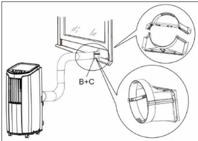
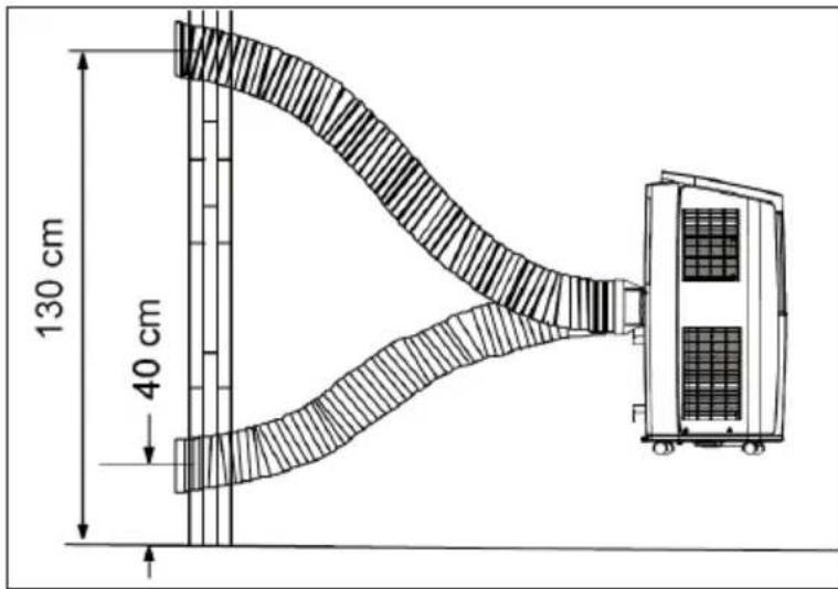
-
Correct installation is as shown in figure. When installing it on a wall, height of hall should be about 40 cm - 130 cm from floor.
-
If the pipe is bent too much, it would easily cause malfunctions.
Manual Removement of collected Water
When using the continuous drainage option from the bottom hole, install drainage pipe before using, other-wise poor drainage will affect normal operation of the unit.
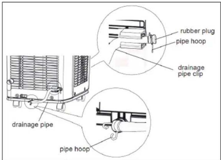
Remove the rubber plug at drainage port. Fix the drainage pipe clip on the right of rear side plate near drainage port with a screw.
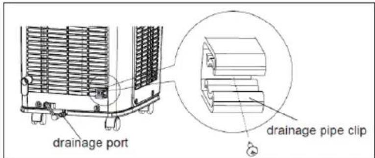
Put the drainage pipe into drainage port and screw it up, and then bind it with pipe hoop.
Put the rubber plug into the other siede of drain- age pipe, fix it with pipe hook and then fix it in the drainage pipe clip.
Drainage way as follows
In cooling or drying operation, the condensation water will be drained to the chassis and spattered by water- striking motor. As the temperature of condenser is high, most of the condensation water will be evaporated and drained to outdoor. So usually, only a little condensation water will be accumulated inside the chassis and you do not need to discharge the water frequently. When the chassis is full with water, the buzzer will give out 8 sounds and „H8“ is displayed to remind user to discharge water:
- Move the unit to a suitable place for discharging water; do not tilt the unit and keep it horizontal during moving.
• Take the drainage pipe from the clip and pull out the rubber plug on the drainage pipe to discharge water.
• After full water protection is eliminated and the compressor has been stopped for 3 minutes, the unit will resume operation.
Using a continuous Drainage
The water can be discharged automatically via the central outlet. You will need the supplied rubber hose, hose adapter and hose clamp. This is how you set up the drain:
| Remove the continuous drain cap 1 by turning it counter clock- wise then remove the rubber stopper 2 from the spout. | Screw the drain connector to(included in the package) the spout by turning clockwise. | Put the hose on the adapter and fasten it with the hose clamp. Guide the free end of the hose into a suitable drain. |
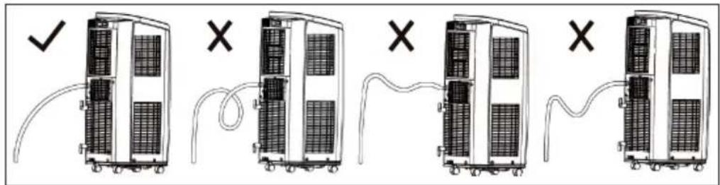
Important Hint on using a continuous Drainage
When using continuous drainage option from the middle hole, place portable on a level surface and make sure garden hose is clear of any obstructions and is directed downward. Placing portable on an uneven surface or improper hose installation may result in water filling up the chassis and causing the unit to shut off. Empty water in the chassis if shut off occurs, then check portable location and hose for proper setup.
CLEANING AND CARE
Before cleaning the air conditioner, please turn off the unit and disconnect power. Otherwise, it may cause electric shock. Do not wash air conditioner with water. Otherwise, it may cause electric shock. Do not use volatile liquid (such as thinner or gas) to clean the air conditioner. Otherwise, it may damage the appearance of air conditioner.
Clean outer Case and Grille
Clean outer case: If there's dust on the surface of outer case, please use soft towel to wipe it. If the outer case is very dirty (such as grease), please use neutral abluent to wipe it. Clean grille: Use cleaner or soft brush to clean it.
Clean Filter
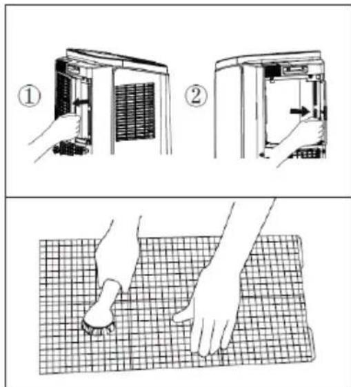
- Remove filter.
- Use clean water to clean the filter. If the filter is very dirty (such as grease), use warm water 40 °C (104 °F) melted with neutral abluent to clean it and then put at shady place to dry it..
• After the filter is cleaned and completely dried, reinstall it well.
Cleaning the Heat Discharge Pipe
Remove the heat discharge pipe from air conditioner, clean and dry it, and then reinstall it. (For the method of installation and removal, please refer to the instruction for „Installation and disassembly of heat discharge pipe”).
Checking before Use-Season
- Check whether air inlets and air outlets are blocked.
- Check whether plug and socket are in good condition.
- Check whether filter is clean.
- Check whether batteries are installed in remote controller.
- Check whether joint, window bracket and heat discharge pipe are installed tightly.
- Check whether heat discharge pipe is damaged.
Checking after Use Season
- Disconnect power supply. Clean filter and outer case.
- Remove dust and sundries on the air conditioner.
- Eliminate accumulated water in chassis (refer to the section of „Drainage way“ for details).
- Check whether window bracket is damaged or not. If yes, please contact dealer.
Long-time Storage
If you don't use the air conditioner for a long time, make sure there's no accumulated water in chassis. Pull out the plug and wrap the power cord. Clean the air conditioner and pack it well to prevent dust.
TROUBLESHOOTING
| Problem Possible Cause Solution | ||
| Air conditioner can't operate. | Is plug loose? Reinsert the plug. | |
| Whether the unit is restarted up after stopping immediately. | Wait for 3min, and then turn it on again. | |
| Poor cooling. The air filter is | too dirty. Clean the air filter. | |
| The set temperature is proper. | Adjust the temperature. | |
| Door and window are not closed. | Close dorrs and windows. | |
| Air conditioner can't receive signal from remote contr-oller or remote controller is not sensible. | Remote controller is not within the receiving range. | The receiving range of remote controller is 8 m. Do not exceed this range. |
| Whether it's blocked by obstacles. | Remove the obstacles. | |
| Is sensitivity of remote controller low. | Check the batteries of remote controller. If the power is low, please replace the batteries. | |
| There's a fluorescence lamp in the room. | Move the remote controller close to air conditioner or turn off the fluorescence lamp and try it again. | |
| No fan blown out from air conditioner. | Air outlet or air inlet is blocked. | Eliminate the obstacles. |
| Set temperature can't be adjusted. | The unit operates under auto mode. | Temperature can't be adjusted under auto mode. |
| The required temperature exceeds the temperature setting range. | Temperature setting range: 16°C-30°C. | |
| There's abnormal sound during operation. | The unit is interfered by thunder, radio, etc. | Disconnect power, put thro-ugh the power again, and then turn on the unit again. |
ERROR CODES
| H8 Chassis is full of water. | Pour out the water inside chassis. If „H8“ still exits, please contact professional person to maintain the unit. | |
| F1 | Malfunction of ambient temperature sensor. | Please contact professional person to deal with it. |
| F2 | Malfunction of evaporator temperature sensor. | Please contact professional person to deal with it. |
| F0 | Refrigerant is leaking or system is blocked. | Re-energize the unit after turning off and pulling out the plug for 30 min; If there's still malfunction, please contact after-sales service. |
| H3 | Overload protection for compressor. | Check if the unit is under high-temperature and high-humidity environment; if ambient temperature is too high, power off the unit and then energize it for operation after the ambient temperature drops to 35 °C below |
| E8 | Overload malfunction. | Check if the evaporator and condenser are blocked by some objects; if yes, take away the objects, power off the unit and then energize it for operation. If the malfunction still occur, please contact our after-sales service center. |
| F4 Outdoor tube temperature sensor is open/short-circuited. | Please contact professional person to deal with it. | |
NOTES ON REFRIGERANT R290
Warnings
- The air conditioning system must be kept and transported upright. Otherwise, irreparable compressor damage may occur. Leave the unit for at least 24 hours before putting it into operation.
- Switch off the device and disconnect it from the power supply before cleaning.
- Make sure that the product creates a steady stream of air. Ensure the air inlets and outlets are not blocked.
• To prevent leaks, operate this unit on a horizontal surface. - Any person performing work on a refrigerant circuit should have a current certificate from an industry-accredited assessment body. This ensures competence for the safe handling of refrigerants according to an industry-recognised assessment specification.
- If the device stops working, dispose of it properly.
- Store the device in a well-ventilated place when not in use.
- Store the device so that it is not damaged.
- Repairs may only be carried out by the manufacturer or an authorised specialist company.
- Do not damage any components of the refrigerant circuit. Escaping refrigerant may not be noticed because it is odourless.
- Maintenance and repairs must be carried out under the supervision of specialists in the use of flammable refrigerants.
Information for rooms with refrigerant pipes
- Limit the piping to a minimum.
- Be careful not to damage the piping.
- Appliances with flammable refrigerants may only be installed in a well-ventilated room.
• Comply with national gas regulations. - All mechanical connections must be freely accessible for maintenance purposes.
CAUTION
Risk of fire! This device contains the fl ammable refrigerant R290. If the refrigerant escapes and is exposed to an external ignition source, there is a risk of fire.
PRODUCT DATA SHEET
Information according to regulation (EU) No. 626/2011
Supplier's trademark:
Klarstein
Supplier's model identifier:
10032511, 10033584
Inside sound power levels at standard rating conditions on cooling mode in dB: 64 dB
Refrigerant (R290) leakage contributes to climate change. Refrigerant with lower global warming potential (GWP) would contribute less to global warming than a refrigerant with higher GWP, if leaked to the atmosphere. This appliance contains a refrigerant fluid with a GWP equal to 3. This means that if 1 kg of this refrigerant fluid would be leaked to the atmosphere, the impact on global warming would be 3 times higher than 1 kg of CO_2 , over a period of 100 years. Never try to interfere with the refrigerant circuit yourself or disassemble the product yourself and always ask a professional.
Energy efficiency ratio ( EER_rated ): 3,1
Energy efficiency class:
A+
Energy consumption 0,9 kWh per 60 minutes, based on standard test results. Actual energy consumption will depend on how the appliance is used and where it is located.
Cooling capacity P_rated in kW:
2,9 kW
Information according to regulation (EU) No. 206/2012
| Model identifier(s) 10032511, 10033584 | |||
| Description Symbol Value Unit | |||
| Rated capacity for cooling P | rated for cooling | 2,9 kW | |
| Rated capacity for heating P | rated for heating | kW | |
| Rated power input for cooling P | EER | 0,9 kW | |
| Rated power input for heating P | COP | -kW | |
| Rated Energy efficiency ratio EERd 3,1 - | |||
| Rated Coefficient of performance COPd | -- | ||
| Power consumption in thermostat-off mode | P_TO | - | W |
| Power consumption in standby mode | P_SB | 0,4 W | |
| Electricity consumption of single/double duct appliances (indicate for cooling and heating separately) | DD: Q_DD SD: Q_SD | 0,9 DD: kWh/aSD: kWh/h | |
| Sound power level | L_WA | 64 | dB(A) |
| Global warming potential | GWP | 3 | kgCO _2 eq. |
| Contact details for obtaining more information | Chal-Tec GmbH, Wallstraße 16, 10179 Berlin, Germany. | ||
DISPOSAL CONSIDERATIONS
natural_image
Symbol of a trash bin crossed with a diagonal line, no text or numbers presentIf there is a legal regulation for the disposal of electrical and electronic devices in your country, this symbol on the product or on the packaging indicates that this product must not be disposed of with household waste. Instead, it must be taken to a collection point for the recycling of electrical and electronic equipment. By disposing of it in accordance with the rules, you are protecting the environment and the health of your fellow human beings from negative consequences. For information about the recycling and disposal of this product, please contact your local authority or your household waste disposal service.
This product contains batteries. If there is a legal regulation for the disposal of batteries in your country, the batteries must not be disposed of with household waste. Find out about local regulations for disposing of batteries. By disposing of them in accordance with the rules, you are protecting the environment and the health of your fellow human beings from negative consequences.
MANUFACTURER & IMPORTER (UK)
Manufacturer:
Chal-Tec GmbH, Wallstrasse 16, 10179 Berlin, Germany.
Importer for Great Britain:
Berlin Brands Group UK Limited
PO Box 42
272 Kensington High Street
London, W8 6ND
United Kingdom
Estimado cliente,
ÍNDICE

flowchart
graph TD
    A["no display"] --> B["House"]
    B --> C["House"]
    C --> D["House"]
    D --> E["House"]
    E --> F["House"]
    F --> G["House"]
    G --> H["House"]
    H --> I["House"]
    I --> J["House"]
    J --> K["House"]
    K --> L["House"]
    L --> M["House"]
    M --> N["House"]
    N --> O["House"]
    O --> P["House"]
    P --> Q["House"]
    Q --> R["House"]
    R --> S["House"]
    S --> T["House"]
    T --> U["House"]
    U --> V["House"]
    V --> W["House"]
    W --> X["House"]
    X --> Y["House"]
    Y --> Z["House"]
natural_image
Technical line drawing of an industrial air conditioning unit with cooling fans and heat exchangers (no text or symbols)LIMPIEZA Y CUIDADO
natural_image
Symbol of a trash bin crossed out by a diagonal line, with no text or labels present.Berlin Brands Group UK Limited
PO Box 42
272 Kensington High Street
London, W8 6ND
United Kingdom
Chère cliente, cher client,
SOMMAIRE

4 Oscillation / SWING
flowchart
graph TD
    A["No display"] --> B["House"]
    B --> C["House Icon"]
    C --> D["House Icon"]
    D --> E["Return to House Icon"]
natural_image
Technical diagram of an air conditioning unit with labeled components and wiring (no text or symbols present)NETTOYAGE ET ENTRETIEN
FICHE DE DONNÉES PRODUIT
natural_image
Symbol of a trash bin crossed with a diagonal line, no text or numbers presentBerlin Brands Group UK Limited
PO Box 42
272 Kensington High Street
London, W8 6ND
United Kingdom
Gentile cliente,
INDICE
flowchart
graph TD
    A["no display"] --> B["recovery via"]
    B --> C
    C --> D
    D --> E
    E --> F
    F --> G
    G --> H
    H --> I
    I --> J
    J --> K
    K --> L
    L --> M
    M --> N
    N --> O
    O --> P
    P --> Q
    Q --> R
    R --> S
    S --> T
    T --> U
    U --> V
    V --> W
    W --> X
    X --> Y
    Y --> Z
natural_image
Technical line drawing of a portable air conditioner unit with cooling fins and ventilation slots (no text or symbols)natural_image
Symbol of a trash bin crossed with a diagonal line, no text or labels presentPRODUTTORE E IMPORTATORE (UK)
Produttore:
Chal-Tec GmbH, Wallstraße 16, 10179 Berlino, Germania.
Berlin Brands Group UK Limited
PO Box 42
272 Kensington High Street
London, W8 6ND
United Kingdom

bar
| Category | Value | |---|---| | Category 1 | 100 | | Category 2 | 100 | | Category 3 | 100 | | Category 4 | 100 | | Category 5 | 100 | | Category 6 | 100 | | Category 7 | 100 | | Category 8 | 100 | | Category 9 | 100 | | Category 10 | 100 | | Category 11 | 100 | | Category 12 | 100 | | Category 13 | 100 | | Category 14 | 100 | | Category 15 | 100 | | Category 16 | 100 | | Category 17 | 100 | | Category 18 | 100 | | Category 19 | 100 | | Category 20 | 100 | | Category 21 | 100 | | Category 22 | 100 | | Category 23 | 100 | | Category 24 | 100 | | Category 25 | 100 | | Category 26 | 100 | | Category 27 | 100 | | Category 28 | 100 | | Category 29 | 100 | | Category 30 | 100 | | Category 31 | 100 | | Category 32 | 100 | | Category 33 | 100 | | Category 34 | 100 | | Category 35 | 100 | | Category 36 | 100 | | Category 37 | 100 | | Category 38 | 100 | | Category 39 | 100 | | Category 40 | 100 | | Category 41 | 100 | | Category 42 | 100 | | Category 43 | 100 | | Category 44 | 100 | | Category 45 | 100 | | Category 46 | 100 | | Category 47 | 100 | | Category 48 | 100 | | Category 49 | 100 | | Category 50 | 100 | | Category 51 | 100 | | Category 52 | 100 | | Category 53 | 100 | | Category 54 | 100 | | Category 55 | 100 | | Category 56 | 100 | | Category 57 | 100 | | Category 58 | 100 | | Category 59 | 100 | | Category 60 | 100 | | Category 61 | 100 | | Category 62 | 100 | | Category 63 | 100 | | Category 64 | 100 | | Category 65 | 100 | | Category 66 | 100 | | Category 67 | 100 | | Category 68 | 100 | | Category 69 | 100 | | Category 70 | 100 | | Category 71 | 100 | | Category 72 | 100 | | Category 73 | 100 | | Category 74 | 100 | | Category 75 | 100 | | Category 76 | 100 | | Category 77 | 100 | | Category 78 | 100 | | Category 79 | 100 | | Category 80 | 100 | | Category 81 | 100 | | Category 82 | 100 | | Category 83 | 100 | | Category 84 | 100 | | Category 85 | 100 | | Category 86 | 100 | | Category 87 | 100 | | Category 88 | 100 | | Category 89 | 100 | | Category 90 | 100 | | Category 91 | 100 | | Category 92 | 100 | | Category 93 | 100 | | Category 94 | 100 | | Category 95 | 100 | | Category 96 | 100 | | Category 97 | 100 | | Category 98 | 100 | | Category 99 | 100 | | Total (Total) = [sum of bars] / [values] * (sum of bars + bars) * (sum of bars + bars) * (sum of bars + bars). The values in the table represent the sum of the bars and the corresponding sum of the bars. There is no additional data series or categories specified in the code.
KLARSTEIN

- INHALTSVERZEICHNIS
- Dear Customer,
- CONTENT
- SAFETY INSTRUCTIONS
- Special notes
- General safety instructions
- Instructions for Handling Damage
- WARNING
- DEVICE OVERVIEW
- CONTROL PANEL AND KEY FUNCTIONS
- REMOTE CONTROL AND INDICATORS
- Indicators of the remote control
- Notes:
- On/Off switch (ON/OFF)
- Up Button (+)
- Mode (MODE)
- Pivoting movement (SWING)
- Down button (-)
- Fan (FAN)
- Automatic switch-off (TIMER OFF)
- Setting the time (CLOCK)
- Automatic power on (TIMER ON)
- TEMP / Temperature setting
- TURBO
- Ventilation mode (X-FAN)
- Light
- WiFi (wireless)
- Health mode - Air cleaning (¥)
- Parental lock
- Setting the temperature in °F or °C
- Energy saving function
- INSTALLATION
- Installing the Wire Hook
- Installing the Heat Discharge Pipe
- Manual Removement of collected Water
- Drainage way as follows
- Using a continuous Drainage
- Important Hint on using a continuous Drainage
- CLEANING AND CARE
- Clean outer Case and Grille
- Clean Filter
- Cleaning the Heat Discharge Pipe
- Checking before Use-Season
- Checking after Use Season
- Long-time Storage
- TROUBLESHOOTING
- NOTES ON REFRIGERANT R290
- Warnings
- Information for rooms with refrigerant pipes
- CAUTION
- PRODUCT DATA SHEET
- DISPOSAL CONSIDERATIONS
- MANUFACTURER & IMPORTER (UK)
- Manufacturer:
- Importer for Great Britain:
- Estimado cliente,
- ÍNDICE
- LIMPIEZA Y CUIDADO
- Chère cliente, cher client,
- SOMMAIRE
- Oscillation / SWING
- NETTOYAGE ET ENTRETIEN
- FICHE DE DONNÉES PRODUIT
- Gentile cliente,
- INDICE
- PRODUTTORE E IMPORTATORE (UK)
- Produttore:
- KLARSTEIN
Brand : Klarstein
Model : New Breeze Eco
Category : Air Conditioning