
LFCE 70N3 - Oven LISTO - Free user manual and instructions
Find the device manual for free LFCE 70N3 LISTO in PDF.

| Brand | Listo |
| Model | LFCE 70N3 |
| Product type | Electric built-in oven |
| Net volume | 70 L |
| Energy class | A |
| Energy consumption (conventional) | 0.79 kWh/cycle |
| Heat source | Electric |
| Number of cavities | 1 |
| Net weight | 27.2 kg |
| Supply voltage | 220-240 V ~ |
| Frequency | 50/60 Hz |
| Nominal power | Not specified in manual, estimated ~2000 W |
| Cooking programs | Light, Top heat, Bottom heat, Natural convection, ECO |
| Temperature range | 50 °C – 250 °C |
| Cleaning type | Catalysis (catalytic walls) |
| Interior lighting | Bulb E14, 25 W, 300 °C |
| Supplied accessories | Metal grid, baking tray |
| Installation | Built-in under counter or wall unit, ventilation required |
| Electrical connection | By a professional, earthing mandatory |
| Warranty | Against manufacturing defects, duration as per invoice |
| Manufacturer | Sourcing & Création, Lesquin, France |
Frequently Asked Questions - LFCE 70N3 LISTO
User questions about LFCE 70N3 LISTO
0 question about this device. Answer the ones you know or ask your own.
Ask a new question about this device
Download the instructions for your Oven in PDF format for free! Find your manual LFCE 70N3 - LISTO and take your electronic device back in hand. On this page are published all the documents necessary for the use of your device. LFCE 70N3 by LISTO.
USER MANUAL LFCE 70N3 LISTO
natural_image
Simple line drawing of a rectangular plate with diagonal hatching and a labeled point '6' (no text or symbols beyond the label)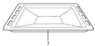
natural_image
Line drawing of a rectangular tray with internal geometric patterns and a labeled dimension '7' (no text or symbols beyond the number)| FR EN DE NL | ||||
| 1 | Bandeau de commandes | Control panel Bedienfeld Bedieningspanee | ||
| 2 | Trou de fixation du cadre | Mounting fixing hole | Loch zur Befestigung des Rahmens | Gat om kader vast te maken |
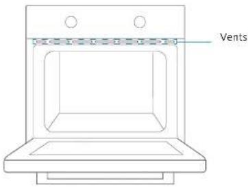
| 3 | Ouvertures de ventilation | Ventilating openings | Lüftungsöffnungen | Ventilatie- openingen |
| 4 | Porte en verre Glass door Glastür Glazen deur | |||
| 5 | Poignée Handle Griff Handgreep | |||
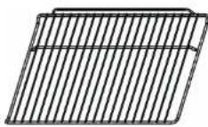
| 6 | Grille métallique Grill rack Metallrost Metalen rooster | |||
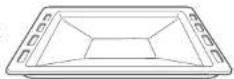
| 7 | Lèchefrite | Grill tray | Auffangschale | Druipplaat |
All information, designs, drawings and pictures in this document are the property of SOURCING & CREATION. SOURCING & CREATION reserves all rights to its brands, designs and information. Any copy and reproduction through any means shall be deemed and considered as counterfeiting.
natural_image
Diagram showing a square container with arrows indicating direction and a magnified view of a droplet inside (no text or symbols)natural_image
Simple line drawing of a two-story dormer cabinet with no text or symbolsnatural_image
Line drawing of a hand cleaning a car window with a circular vent (no text or symbols)natural_image
Diagram showing two views of a door with internal compartments and a triangular structure (no text or symbols)natural_image
Technical line drawing of a mechanical component with a magnified inset showing a downward arrow (no text or symbols)natural_image
Diagram of a door frame with an 30-degree angle indicator and directional arrows (no text or symbols)WARNING: This appliance must be installed by an authorised professional or by a qualified technician, in accordance with the instructions in this manual and in accordance with the installation standards in force.
- Improper installation invalidates the warranty and may result in damage or injury for which the manufacturer cannot be held responsible.
- Before installation, make sure that the local distribution conditions (electrical voltage and frequency) and the appliance setting are compatible. The conditions for setting this appliance are listed on the label.
- The laws, regulations, decrees and standards in force in the country of installation must be applied (safety rules, recycling in accordance with regulations, etc.).
Instructions for the installer General instructions
- For the oven to work properly, the kitchen unit must be in a suitable location.
- After removing the packaging materials from the appliance and its accessories, check that the appliance is not damaged. If the appliance may be damaged, do not use it and contact an authorised professional or a qualified technician immediately.
- Check that no combustible or flammable element or material, for example a curtain, oil, fabric, etc., is in the immediate vicinity.
- The panels of the kitchen unit next to the oven must be made of a heat-resistant material. Make sure that the adhesives on veneered wood elements are resistant to temperatures of at least 120^ . Plastics or adhesives that do not withstand such temperatures will melt and distort the appliance.
- This appliance should not be installed directly above a dishwasher, refrigerator, freezer, washing machine or tumble dryer.
- Once the oven is integrated, the electrical parts must be completely insulated. This is a legal safety requirement. All the protective elements must be securely fastened so that they cannot be removed without special tools.
Installing the oven in the kitchen unit
• Install the oven in the space provided in the kitchen unit.
- It can be installed under a worktop or in a tall unit.
- To allow adequate ventilation, the measurements and distances must be respected when fixing the oven.
- Remove the back of the kitchen unit to ensure adequate air flow around the oven.
• The hob must have a space of at least 45mm at the rear.
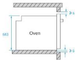
Integrated installation in a tall unit
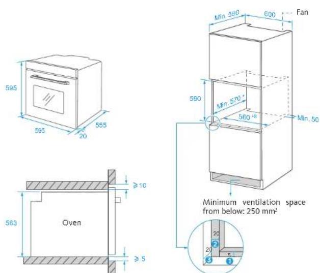
① Allow 5 mm for the frame at the top and bottom.
② Allow 20 mm for the frame on the left and right.
③ Allow a gap of 20 mm for the frame.
- The thickness of the unit is 20 mm.
- If the power socket is installed at the rear of the appliance, the depth of the opening in the unit must be increased from a minimum of 590mm to 620mm.
- The dimensions in the diagrams above are expressed in mm.
Integrated installation under a worktop
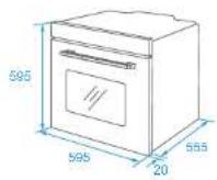
① Allow 5 mm for the frame at the top and bottom. ② Allow 20 mm for the frame on the left and right. ③ Allow a gap of 20 mm for the frame.
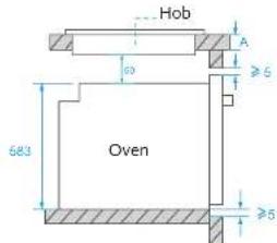
With hob
If the oven is installed under a hob, the minimum thickness of the work surface A must be as indicated below:
| Type of hob Worktop A | |
| Induction hob 37 mm | |
| Induction hob on the entire surface | 47 mm |
| Gas hob 30 mm | |
| Electric hob 27 mm |
- The thickness of the unit is 20 mm.
- If the power socket is installed at the rear of the appliance, the depth of the opening in the unit must be increased from a minimum of 590mm to 620mm.
- The dimensions in the diagrams above are expressed in mm.
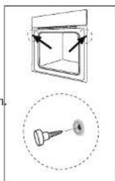
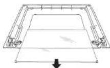
When the electrical connections have been made, insert the oven into its location by pushing it forwards. Open the oven door and insert 2 screws into the holes in the frame of the oven. When the frame of the product touches the surface of the wood of the unit, tighten the screws.
natural_image
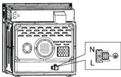
Technical diagram showing a square enclosure with arrows pointing to its top panel and a magnified view of a pin (no text or symbols present)Electrical connections
WARNING: The electrical connection of this appliance must be carried out by a licensed professional or a qualified electrician, in accordance with the instructions in this manual and in accordance with the installation standards in force.
WARNING: THE APPLIANCE MUST BE CONNECTED TO EARTH.
- Before connecting to the mains, check whether the rated voltage of the appliance (marked on the rating plate of the appliance) corresponds to the voltage of the power supply. The power supply cord must also be capable of withstanding the rated power of the appliance (also mentioned on the rating plate of the appliance).
- When installing, make sure to use properly insulated cables. Improper connection may damage your appliance. If the power supply cord is damaged and must be replaced, call a qualified person to carry out this operation.
- Do not use an adapter, power strip, or extension cord.
- The power cord must be kept away from hot parts of the appliance and must not be bent or crushed. Otherwise, the cord may be damaged and cause a short circuit.
- If the appliance is not connected to the mains by a socket, install a multi-pole isolating switch (with a contact spacing of at least 3 mm), in accordance with safety regulations.
- This appliance is designed to operate with a 220-240 V\~ power supply. If your power supply is different, contact a licensed professional or qualified electrician.
- The power cord (H05VV-F) must be long enough to be able to be plugged into the appliance, even if the appliance is in front of the cabinet.
- Check that all connections are properly tightened.
- Attach the power cord to the terminal block, and then close the cover.
- The connection of the junction box is placed on the junction box.
Vents
When cooking is finished, if the temperature at the vents exceeds 70^ C, the cooling fan will continue to operate. The cooling fan will only stop working when the temperature drops below 60^ C.
USING THE APPLIANCE
Control panel description
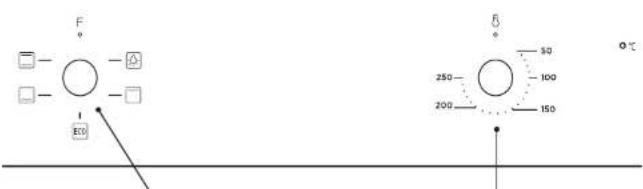
Program selection knob Oven temperature control knob
Oven controls
Program selection knob
Turn the knob to the symbol of the program you want. For details of the different programs, refer to the "Oven programs" section.
Oven temperature control knob
After selecting a program, turn this knob to adjust the temperature. The oven thermostat light comes on as soon as the thermostat works to heat up the oven or keep it at a set temperature.
Oven programs
Oven light: allows the user to monitor the progress of the cooking without opening the door. The oven light will come on for all cooking programs except the ECO program.
☐ Upper: Only the upper heating element switches on. This program is ideal for browning already cooked food and for warming up food.
ECO: For energy-efficient cooking. The lower and upper heating elements switch on. Gentle cooking.
Lower: The lower heating element switches on. Use this program to warm up pizzas as the heat comes from the bottom of the oven and heats the pizza from below. This program is better for warming up food rather than cooking it.
Natural convection: The lower and upper heating elements switch on. Even cooking. This program is ideal for pastries, cakes, gratins, lasagna, etc. Preheat the oven for 10 minutes and use only one level at a time in this mode.
Use
- Turn the program selector to the program of your choice. You can choose from 4 cooking programs. Refer to the "Cooking programs" section.
- Set the temperature by turning the temperature control knob. You can select a temperature between 50 and 250°C.
- When you have finished, always return the two knobs to the "0" (off) position.
Cooking table for the ECO program
| Dish | Temperature (in °C) | Cooking level | Cooking time (in min) | Pre-heating |
| Potato gratin with cheese | 180 1 90 | 100 No | ||
| Cheesecake 160 1 | 100 - 150 No | |||
| Meatloaf 190 1 110 | - 130 No |
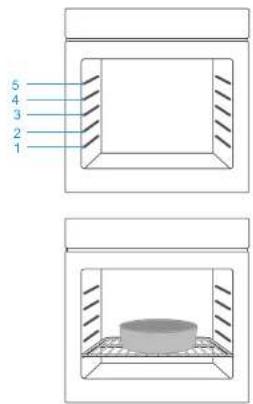
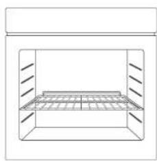
Cooking levels
For the oven to work properly, the wire rack and drip pan must be placed between the first and fifth levels. When used together, place the drip pan under the wire rack.
natural_image
Two identical technical diagrams showing a rectangular container with internal structure and side supports, no text or symbols present.V.3.0
24
Accessories
Drip pan
The drip pan is used to collect cooking juices and fat. Place it on the lowest level. Make sure you position it correctly by pushing it all the way in.
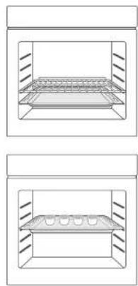
Wire rack
The rack is used for grilling or for placing cookware.
The rack must be inserted in the right direction. This is to prevent hot food from sliding off when the rack is carefully withdrawn.
Refer to the diagram below to place the rack in the right direction.
natural_image
Simple line drawing of a rectangular enclosure with internal grid structure (no text or symbols)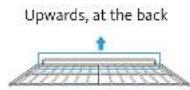
25
V.3.0
CLEANING AND MAINTENANCE
Cleaning

WARNING: Stop the appliance and allow it to cool down before cleaning it.
General instructions
- Check that the cleaning products are appropriate and recommended by their manufacturer before using them on the appliance.
- Use a cleaning cream or cleaning fluid that does not contain particles. Do not use caustic (corrosive) creams, abrasive cleaning powders, steel wool or excessively hard utensils, as they may damage the surfaces of the appliance.

Do not use cleaning products containing particles, as they may scratch the glass and the enamelled and painted parts of your appliance.
- Immediately clean up any spilled liquid to prevent the various parts from being damaged.

Do not use a steam cleaner to clean the various parts of the appliance.
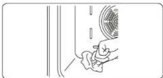
Cleaning the inside of the oven
- The best time to clean the enamel surfaces inside the oven is when the oven is still a little warm.
• After each use, wipe the oven with a soft cloth dipped in water. Then wipe the oven again with a damp cloth and dry it.
• It will be useful to occasionally use a specific cleaning product to fully clean the oven.
natural_image
Line drawing of a hand cleaning a car window with a circular vent (no text or symbols)Catalytic cleaning
Catalytic walls are installed in the oven cavity. These are the light-coloured matte panels placed on the sides of the oven and/or the matte panel which is at the rear of the oven. They collect grease and oil residues during cooking.
The protective surface is cleaned automatically by absorbing the grease and oil spatter and burning it. They decompose into ash that can be easily recovered from the oven floor. The protective surface must be porous to remain effective. The protective surfaces may become discoloured over time.
If a large amount of grease accumulates on the protective surface, it may become less effective. To solve this problem, set the oven to the maximum temperature for 10 to 20 minutes. Once the oven has cooled, clean the oven floor.
It is not recommended to clean the catalytic walls by hand. The protective surfaces can be damaged by scouring pads or other abrasive surfaces. In addition, the use of cleaning aerosols on the protective surfaces is not recommended. The catalytic walls may become less effective if there is an excessive accumulation of grease. This excess grease can be cleaned with a soft cloth or a sponge dipped in water. Then carry out the cleaning cycle described above.
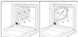
Removing the catalytic walls
To dismantle the catalytic wall, remove the screws that hold each wall in the oven.
natural_image
Two-panel line drawing showing a door opening with internal compartments and directional arrows, no text or symbols present.Cleaning the glass surfaces
- Clean the glass surfaces of the appliance regularly.
- Use a glass cleaner to clean the inside and outside of the glass surfaces. Rinse them and then dry them with a dry cloth.
Cleaning the stainless steel surfaces (if applicable)
- Clean the stainless steel surfaces of the appliance regularly.
- Wipe the stainless steel parts using a soft cloth dipped in pure water. Rinse them and then dry them with a dry cloth.

Do not clean the stainless steel surfaces while they are still hot after cooking. Do not leave vinegar, coffee, milk, salt, water, lemon juice or tomato juice on stainless steel surfaces for too long.
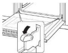
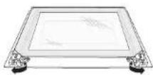
Removing the oven door
- Open the oven door fully. Rotate the door latch forwards.
natural_image
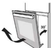
Technical line drawing of a mechanical component with an inset showing a downward arrow (no text or symbols)- Close the door to an angle of approximately 30°. Hold the door with one hand on each side. Lift and carefully remove the oven door.
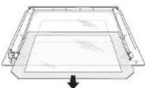
natural_image
Diagram of a door or shelf with an arrow indicating 30° angle, no text or symbols present- Open the door rotation bracket assembly. Refer to the diagram below.
- Lift the outer door glass and remove it, then remove the middle door glass in the same manner.
WARNING:
Do not use force when removing the door as this could cause the glass to break during disassembly.
WARNING:
The hinge springs could become loose and cause an injury.
WARNING:
Do not lift or carry the oven door by its handle.
Maintenance

WARNING: Maintenance operations on this appliance must be carried out only by an authorised professional or a qualified technician.
Oven light replacement

WARNING: Turn off the appliance and allow it to cool before replacing the bulb.
- Unplug the oven from the power socket or trip the circuit breaker.
- Unscrew the glass cover of the light by turning it anticlockwise (warning: it may be stiff) and replace the bulb with a new one of the same type: type E14, 25 W, 230 V\~, resistant to 300°C.
- Screw the light cover back on.

The bulb must be specifically designed for use in household cooking appliances. Bulbs intended for lighting rooms are not suitable.
TROUBLESHOOTING AND TRANSPORT
Troubleshooting

If the problem persists on your appliance after following these basic troubleshooting steps, contact a licensed professional or qualified technician.
| Problems Possible causes Solutions | ||
| The oven does not turn on. | The power supply is cut off. | Check that the power supply is connected.Also check that the other kitchen appliances are working. |
| No heat is produced or the oven does not preheat. | The oven temperature setting is incorrect.The oven door is left open. | Check that the temperature control knob of the oven is set correctly. |
| The oven lighting (if present) does not work. | The bulb does not work.The power supply is cut or disconnected. | Replace the bulb according to the instructions.Check that the power supply is connected to the power outlet. |
| Cooking is uneven. | The baking sheets/grills are incorrectly positioned. | Check compliance with the recommended temperatures and levels.Do not open the door frequently unless the dish needs to be turned. Opening the door too often causes the temperature in the oven to drop, which can have an impact on the cooking result. |
Transport
If it is necessary to transport the product, place it in its original packaging and its original box. Follow the transport instructions on the packaging. Using adhesive tape, fix the moving parts to the product in order to avoid any damage during transport. If you no longer have the original packaging, prepare a cardboard box to protect the appliance (especially the external surfaces) from external risks.
V.3.0
30
TECHNICAL SPECIFICATIONS
Energy sheet
Measurements made according to EU Regulation No. 66/2014 of the European Commission and standard EN 60350-1:2013
| Brand | LISTO | |
| Model LFCE 70n3 | ||
| Type of oven Built-in Oven | ||
| Appliance mass kg 27.2 | ||
| Energy efficiency index - conventional 94.0 | ||
| Energy efficiency index - fan - | ||
| Energy class A | ||
| Energy consumption (electricity) - conventional kWh/cycle 0.79 | ||
| Energy consumption (electricity) - fan | kWh/cycle | - |
| Number of cavities | 1 | |
| Heat source | ELECTRIC | |
| Volume | L | 70 |
Energy saving tips
Oven
- Cook meals at the same time, if possible.
- Reduce the preheating time.
- Don't extend the cooking time.
- Don't forget to switch off the oven at the end of cooking.
- Don't open the oven door during cooking.
| Product Information for power consumption and maximum time to reach applicable low power mode | |
| Power consumption in off mode | 0 W |
| Power consumption in standby | NA |
| The maximum time needed to automatically reach the applicable low power mode or condition | >30' |
| Power consumption in network standby if all wired network ports are connected and all wireless network ports are activated | NA |
31
V.3.0
natural_image
Diagram showing a square container with arrows pointing to its side and a magnified view of a screw head (no text or symbols)Stromanschluss
Lüftungsöffnungen
natural_image
Simple line drawing of a rectangular container with internal grid structure (no text or symbols)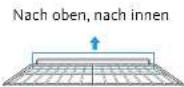
39
V.3.0
natural_image
Line drawing of a hand cleaning a car window with a circular vent (no text or symbols)natural_image
Diagram showing two views of an oven with internal compartments and mounting points (no text or symbols)natural_image
Technical line drawing of a mechanical component with an inset showing a hand holding a knob (no text or symbols)natural_image
Diagram of a door frame with an 30-degree angle indicator and directional arrows (no text or symbols)natural_image
Diagram showing a 3D box with arrows pointing to its front face and a close-up of a pointed tool with label 'A' (no text or symbols present)WAARSCHUWING: DIT TOESTEL DIENT GEAARD TE WORDEN.
Ventilatieopeningen
natural_image
Simple line drawing of a rectangular enclosure with a horizontal shelf and vertical supports (no text or symbols)natural_image
Line drawing of a hand cleaning a car window with a circular vent (no text or symbols)natural_image
Two technical line drawings of a door frame with internal compartments and mounting holes (no text or symbols)Glazen legplanken reinigen
natural_image
Technical line drawing of a mechanical component with an inset showing a downward arrow (no text or symbols)natural_image
Diagram of a door frame with an 30-degree angle indicator and directional arrows (no text or symbols)PROBLEEMOPLOSSING EN TRANSPORT
Probleemoplossing

natural_image
Symbol of a trash bin crossed with two crossed lines, no text or numbers presentATTENTION :
This symbol attached to the product means that it is an appliance whose disposal is subject to the directive on waste from electrical and electronic equipment (WEEE). This appliance may not in any way be treated as household waste and must be subject to a specific type of removal for this type of waste. Recycling and recovery systems are available in your area (waste removal) and by distributors. By taking your appliance at its end of life to a recycling facility, you will contribute to environmental conservation and prevent any harm to your health.
Warranty conditions:
This product is under warranty against any failure resulting from any manufacturing or material defects. This warranty does not cover defects or damage caused by improper set up, incorrect use, or normal wear and tear of this product. The warranty period is specified on the receipt of the purchase.
ACHTUNG:
- Instructions for the installer General instructions
- Installing the oven in the kitchen unit
- Integrated installation under a worktop
- Electrical connections
- WARNING: THE APPLIANCE MUST BE CONNECTED TO EARTH.
- Vents
- USING THE APPLIANCE
- Control panel description
- Oven controls
- Program selection knob
- Oven temperature control knob
- Oven programs
- Use
- Cooking levels
- Accessories
- Drip pan
- Wire rack
- CLEANING AND MAINTENANCE
- Cleaning
- General instructions
- Cleaning the inside of the oven
- Catalytic cleaning
- Removing the catalytic walls
- Cleaning the glass surfaces
- Cleaning the stainless steel surfaces (if applicable)
- Removing the oven door
- Maintenance
- Oven light replacement
- TROUBLESHOOTING AND TRANSPORT
- Troubleshooting
- Transport
- TECHNICAL SPECIFICATIONS
- Energy sheet
- Energy saving tips
- Oven
- Stromanschluss
- Lüftungsöffnungen
- WAARSCHUWING: DIT TOESTEL DIENT GEAARD TE WORDEN.
- Ventilatieopeningen
- Glazen legplanken reinigen
- PROBLEEMOPLOSSING EN TRANSPORT
- Probleemoplossing
- ATTENTION :
- Warranty conditions:
- ACHTUNG:
Brand : LISTO
Model : LFCE 70N3
Category : Oven