
SRD991 - Industrial actuator SCHNEIDER - Free user manual and instructions
Find the device manual for free SRD991 SCHNEIDER in PDF.

| Product Type | Industrial actuator (smart positioner) |
| Brand | Schneider |
| Model | SRD991 |
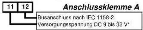
| Power supply | 9 to 32 V DC |
| Input signal | 4-20 mA (bus per IEC 1158-2) |
| Air supply pressure | 1.4 to 6 bar |
| Angular working range | ±45° around the center position |
| Mounting types | Linear left/right, rotary clockwise/counterclockwise, direct |
| Pneumatic connections | G1/4 or NPT (according to marking) |
| Pneumatic outputs | y1 (single acting) / y1, y2 (double acting) |
| Limit switches | Inductive two-wire sensors (DIN 19234/NAMUR) or dry contacts |
| Board options | Binary outputs, binary inputs, 4-20 mA retransmission + alarm, binary inputs/outputs |
| Display | LCD screen |
| Configuration | Local push buttons |
| Autostart function | Mechanical stop, Standard, Optimized, Damped, Aggressive |
| Communication | Profibus PA, Foundation Fieldbus H1 (depending on variant) |
| Protection | Do not exceed max pressure; mandatory grounding |
| Maintenance | Check pneumatic and electrical connections; periodic calibrations |
| Safety | Never touch moving parts; use original parts |
| Repairability | Spare parts available (options, IP, amplifier) |
Frequently Asked Questions - SRD991 SCHNEIDER
User questions about SRD991 SCHNEIDER
0 question about this device. Answer the ones you know or ask your own.
Ask a new question about this device
Download the instructions for your Industrial actuator in PDF format for free! Find your manual SRD991 - SCHNEIDER and take your electronic device back in hand. On this page are published all the documents necessary for the use of your device. SRD991 by SCHNEIDER.
USER MANUAL SRD991 SCHNEIDER
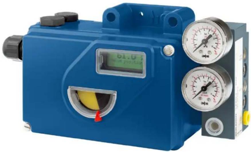
SRD991 Intelligent Positioner
natural_image
Blue industrial pressure regulator device with digital display and dual gauges (no visible text or symbols)Quick Guide ..... (English)
These instructions are to be used as a guide for quick start-up. For more detailed information, please refer to the standard documents "Master Instructions" and "Product Specification Sheet". These can be found on our Website.
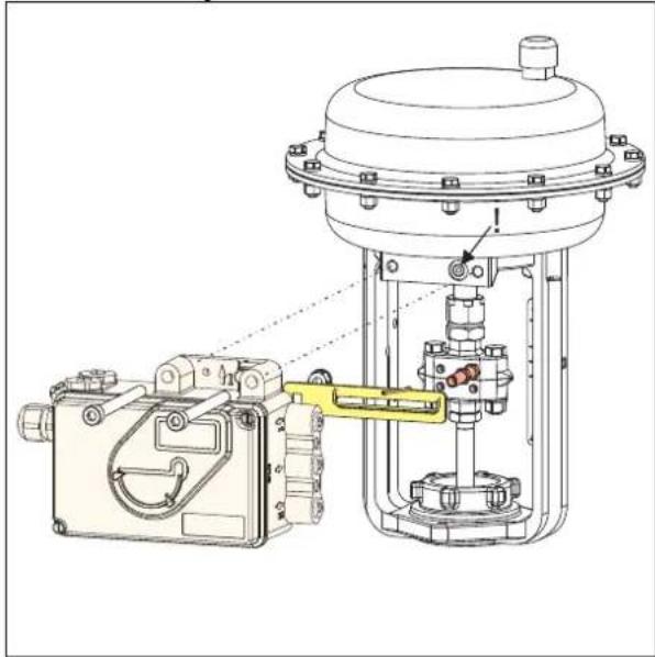
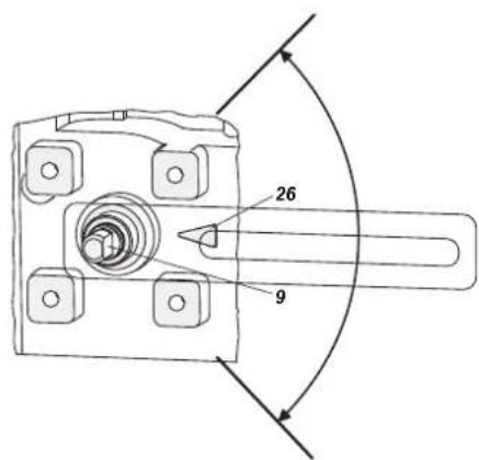
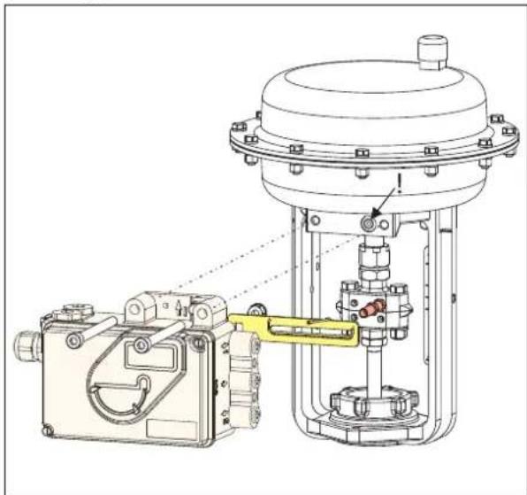
1. MOUNTING TO ACTUATORS
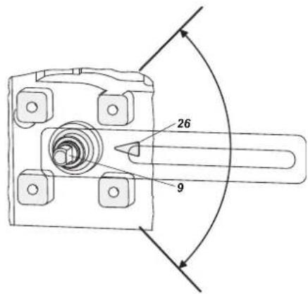
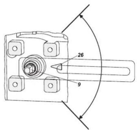
During operation, the flat side of the spindle 9 on the back of the positioner must always point towards the arrow 26. The working angle around this position is ± 45^ .
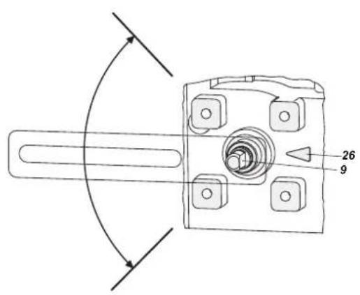

Any mechanical backlash may be source of poor control, oscillation and hunting as well as long duration of Autostart. Please use only original mounting parts and ensure that they are correctly mounted and tighten. By not using the original feedback lever or by using them in an inappropriate way, the performance of the positioner may be compromised.
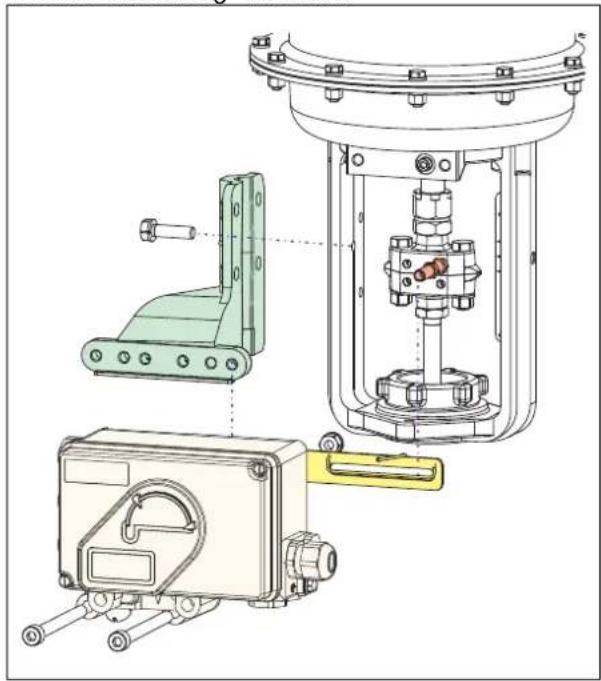
MOUNTING TO LINEAR ACTUATORS
NAMUR Mounting - left hand -
natural_image
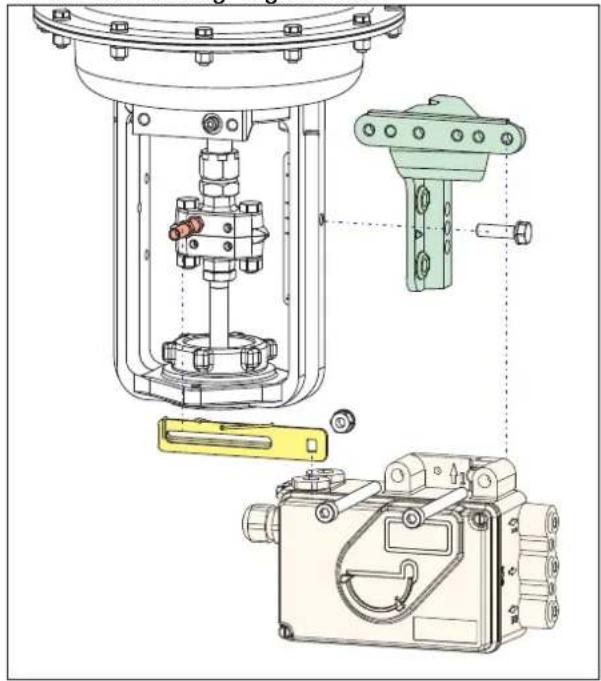
Technical line drawing of mechanical assembly components (no text or symbols)NAMUR Mounting - right hand -
natural_image
Technical diagram of a mechanical assembly with exploded view, showing internal components and mounting features (no text or labels)The carrier bolt B is in the slot of the feedback lever A and the compensating spring F touches the carrier bolt.
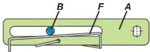
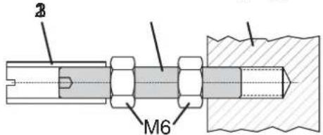
Carrier bolt B:
1 threaded sleeve 2 Stud 3 coupling piece
Direct Mounting
natural_image
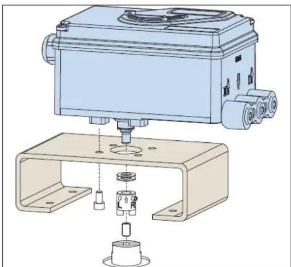
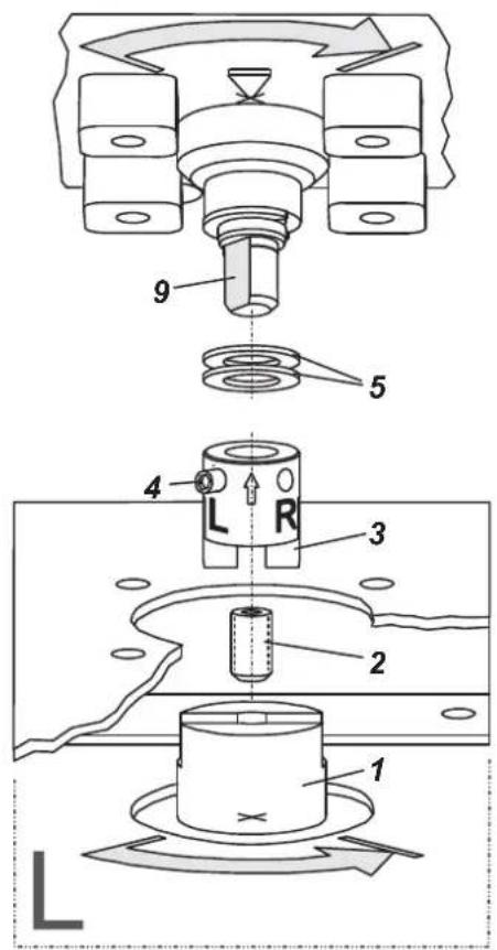
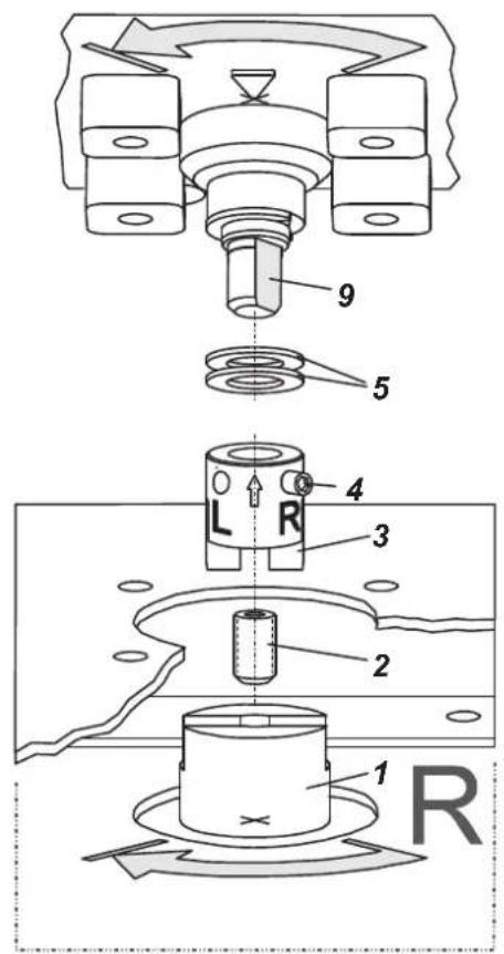
Technical line drawing of a mechanical device with no visible text or symbolsMOUNTING TO ROTARY ACTUATORS
- Do not tighten grub screw 4 against the thread of spindle 9! (see next page).
- When in use the flat side of the spindle 9 must move (0 ↔ 100%) in front of the arrow 26.
natural_image
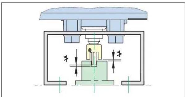
Technical illustration of a mechanical assembly with exploded view and assembled part (no text or symbols)- When the product temperature rises, the drive shaft 1 increases in length. Therefore, the rotary adapter 3 must be mounted so that approx. 1 mm (0.04 in.) of clearance results between the drive shaft 1 and the rotary adapter 3. This is achieved by placing an appropriate number of washers 5 on the feedback spindle 9 before attaching the rotary adapter. Two washers should result in a clearance of 1 mm.
natural_image
Cross-sectional diagram of a mechanical or electrical component with internal components and directional arrows (no text or symbols)Actuator, left turning Actuator, right turning
2. CONNECTIONS
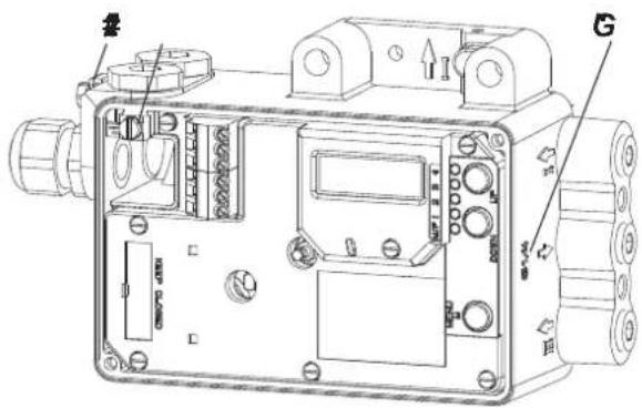
Check before mounting fittings and cable glands that the threads are matching; otherwise the housing can be damaged. The letter "G" on the housing marks where the pneumatic connections are in G 1/4 (otherwise NPT).
Ground
Connect earth cable to screw #1 (or screw #2 in the electrical connection compartment).
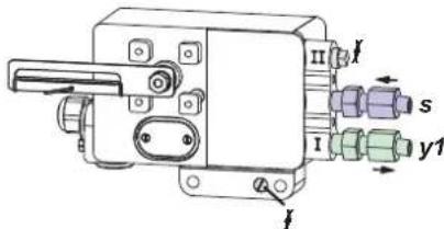
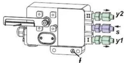
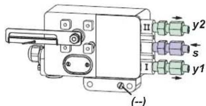
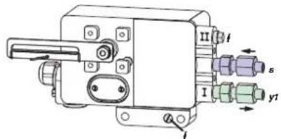
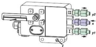
PNEUMATIC CONNECTIONS
WARNING
To avoid any personal injury resulting from bursting of parts, do not exceed maximum supply pressure of positioner and actuator. To avoid any personal injury or property damage from sudden or fast movement, during air connection: Do not put your finger or other part at any time inside the valve or in any moving part of the actuator or in the feedback lever mechanism. Do not touch the rear part of the positioner at any time. Connect air supply only after connections y1 (and y2 for double acting) are done. Air supply (s): 1.4 to 6 bar (but not more than the max. pressure of actuator), free of oil, dust and water!
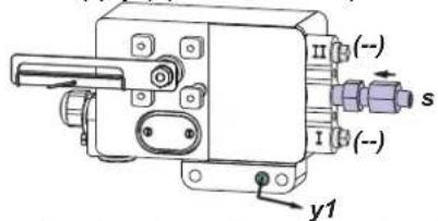
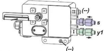
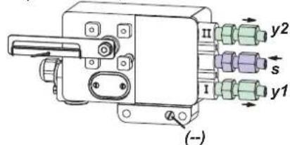
Single acting, Direct mounting Single acting Double acting supply y1, y2 pneumatic outputs (--) closed
3. ELECTRICAL CONNECTIONS
The safety requirements of document EX EVE0001 as well as the requirements of PSS EVE0105 and MI EVE0105 for SRD991 must be observed!
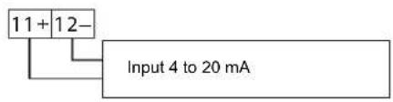
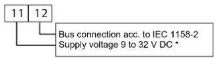
3.1 Setpoint Electric Terminal A
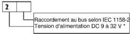
3.1.1 SRD991-xD (w/o communication) SRD991-xH (HART)
3.1.3 SRD991-xP (PROFIBUS PA) SRD991-xQ (FIELDBUS FF)

3.2 Inductive Limit Switch Electric Terminal C
3.2.1 SRD991-xxxT or U
Two-wire proximity sensors, 3.2.2 SRD991-xxxR acc. to DIN 19234 or NAMUR
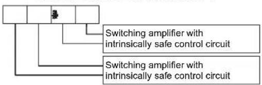
flowchart
graph TD
    A[" "] --> B["Switching amplifier with intrinsically safe control circuit"]
    A --> C["Switching amplifier with intrinsically safe control circuit"]
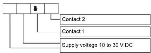
flowchart
graph TD
    A[" "] --> B[" "]
    B --> C["Contact 2"]
    B --> D["Contact 1"]
    B --> E["Supply voltage 10 to 30 V DC"]
3.2.3 SRD991-xxxV
Warning: For connection of micro switches please refer to MI (Master Instruction) and obey the safety requirements described in document EX EVE0001.
3.3 Option Board Electric Terminal B
3.3.1 Two binary outputs (SRD991-xxP)
Two-wire system, acc. to DIN 19234 or switched output.
flowchart
graph TD
    A[" "] --> B["External power supply (e.g. intrinsically safe control circuit)"]
    C[" "] --> D["External power supply (e.g. intrinsically safe control circuit)"]
3.3.2 Two binary inputs (SRD991-xxB)
Binary inputs with internal supply for connection of sensors or switches (switch closed for a normal operation!)
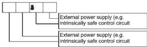
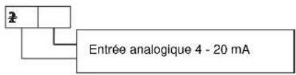
3.3.3 Position feedback 4 to 20 mA and 1 Alarm (SRD991-xxQ ou SRD991-xxF)
Analog output 4-20 mA and Binary output Two-wire system acc. to DIN 19234 or switched.

flowchart
graph TD
    A[" "] --> B["Analog output 4 to 20 mA, Two-wire system, supplied with external power supply"]
    A --> C["External power supply (e.g. intrinsically safe control circuit)"]
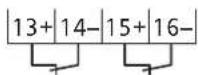
3.3.4 Two binary in-/outputs (SRD991-xxE)
Two-wire system acc. to DIN 19234 or switched in-/output.
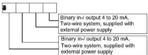
* For intrinsically safe circuits please refer to certificate / data label for max. operating voltages etc.
4. START UP (Setting by means of local keys and LCD)
After mounting the positioner on the actuator, air and electrical input connected, you can start-up the SRD. The positioner can be adjusted by means of a local key-pad and LCD.
WARNING
To avoid any personal injury or property damage from sudden or fast movement, during configuration: Do not put your finger or other part at any time inside the valve or in any moving part of the actuator or in the feedback lever mechanism. Do not touch the rear part of the positioner at any time.
Push buttons

Enter / store
simu
IN OPERATION:
An already configured device may show the following display:
87.5%
Valve position
Process variable
For configuration press (M) and Main menu appears.
CONFIGURATION with push buttons and LCD:
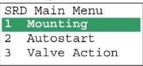
If the SRD wasn't configured yet, the Main menu*) appears automatically after power-up:
| SRD Main Menu | |
| 1 | Mounting |
| 2 | Autostart |
| 3 | Valve Action |
(The selected item is displayed with dark background.)
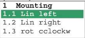
In menu 1 you select the type of mounting: Press keys (UP)+(DOWN) simultaneously to enter this menu.
Select your 'Type of mounting' by pressing (UP) or (DOWN).
Press keys (UP)+(DOWN) simultaneously to confirm and save. The SRD moves back to Main menu again.
To enter next menu (= menu 2, Autostart) press (UP) once:
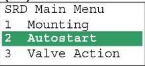
Now press keys (UP)+(DOWN) simultaneously to enter menu 'Autostart'. (Continued on next page.)
Several Autostart options are available. Select relevant Autostart by pressing (UP) or (DOWN):
2 Autostart
2.1 Endpoints
2.2 Standard
2.3 Enhanced
2.4 Smooth resp.
2.5 Fast resp.
→ Determines only the mechanical stops of actuator / valve
→ Recommended for standard applications
→ Optimized control behaviour compared to Standard Autostart
→ Dampened control behaviour for e.g. smaller actuators
→ Undampened control behaviour for e.g. larger actuators
Press keys (UP)+(DOWN) simultaneously to confirm and to launch Autostart. The automatic adaptation to the actuator is composed of a sequence of steps indicated on the LCD.
With the last step the device is IN OPERATION:
87.5 %
Valve position
Process variable
87.5 %
Valve position Ctrl diff error
Diagnostic messages see following table.
5 TROUBLE SHOOTING (For more details see MI EVE0105 E)
Autostart err 1
| Description of message / LCD text Remedy | |
| Air supply too low Check air supply | |
| Feedback lever (linear actuator) or Coupling (rotary actuator) incorrectly linked. Potentiometer moves out of operating range of ± 47^ of 0^ position | Check mounting. Flat area points to arrow on housing |
| Coupling (rotary actuator) incorrectly linked (R and L interchanged) | Check mounting |
| Pneumatic output to actuator closed or untight.When direct mounting onto FlowTop or FlowPak,the screw plug y1-d is not removed | Check pneumatic connections |
| Mechanical stops not determinable Check spring movement of actuator /check air supply / Check mounting | |
| When using a booster or spool valve, no control parameters can be determined, since air capacity is too high | Device version is not suitable for this actuator;select version with smaller air capacity or remove booster |
| Control parameter too high since air capacity is too high (in general, oscillation in valve movement) | Use a booster or the version with spool valve.Reduce control parameter prop.-gain (Menu 6.1 and 6.2) to Code 10 = value 26.6. |
| Possibly incomprehensible configuration data Reset configuration, see Menu 9.1 | |
Optionboard err
| Description of message / LCD text Remedy | |
| Configured status of the SRD deviates from existing version (e.g. Option board has been inserted subsequently) | Check if correct option board has been connected Confirm message by pressing keys (UP)+(DOWN) simultaneously |
| Bad contact Connections to terminals interchanged | Check connections Tighten electronics |
| Defective Exchange option board |
Ctrl diff error
| Description of message / LCD text Remedy | |
| Actuator problems (high friction or blocked) Check actuator | |
| Insufficient air supply Check air supply / air filter | |
| Insufficient parameters for position controls,for example, amplification too small | Check control paramter,check pneumatic components |
| IP module or pneumatic amplifier defect Check with | Menu 7; replace if necessary |
6 MENU STRUCTURE FOR SRD991 / SRD960
SRD Main Menu
| Menu Factory | configuration | Description | |
| 1 Mounting | |||
| 1.1 Lin left √ | Linear actuator, left-hand or direct mounting | ||
| 1.2 Lin right | Linear actuator, right-hand mounting | ||
| 1.3 Rot cclockw | Rotary actuator, opening counter-clockwise | ||
| 1.4 Rot clockw | Rotary actuator, opening clockwise | ||
| 1.5 Linear | For Top Mounting (only for SRD991) | ||
| 2 Autostart | |||
| 2.1 Endpoints | Adaptation of the mechanical stops only | ||
| 2.2 Standard | Autostart recommended for standard application | ||
| 2.3 Enhanced | Enh. Autostart. Optimized control behaviour compared to Standard Autostart | ||
| 2.4 Smooth resp. | Enh. Autostart. Dampened control behaviour for e.g. smaller actuators | ||
| 2.5 Fast resp. | Enh. Autostart. Undampened control behaviour for e.g. larger actuators | ||
| 3 Valve Action | |||
| 3.1 SRD | Action of Positioner: | ||
| 3.1.1 Direct √ | Valve opens with increasing setpoint value | ||
| 3.1.2 Reverse | Valve closes with increasing setpoint value | ||
| 3.2 Feedback | Action of Feedback Unit: | ||
| 3.2.1 Direct √ | Increasing Current with increasing valve position | ||
| 3.2.2 Reverse | Decreasing Current with increasing valve position | ||
| 4 Character | |||
| 4.1 Linear √ | Linear characteristic | ||
| 4.2 Eq Perc 1:50 | Equal percentage characteristic 1:50 | ||
| 4.3 Quick open | Inverse equal percentage characteristic 1:50 (quick opening) | ||
| 4.4 Customer | Custom characteristic (Configuration via DTM) | ||
| 5 Limits/alarms | (Not locally available with LED versions of communication FF and Profibus) | ||
| 5.1 Lower limit 0 % | Closing limit is set to input value | ||
| 5.2 Cutoff low 1 % | 0%-tight sealing point is set to input value | ||
| 5.3 Cutoff high 100 % | 100%-tight sealing point is set to input value | ||
| 5.4 Upper limit 100 % | Opening limit is set to input value | ||
| 5.5 Splitr 0 % 4 mA | Split range 0 %: input value corresponds to 0 % | ||
| 5.6 Splitr 100 % 20 mA | Split range 100 %: input value corresponds to 100 % | ||
| 5.7 Lower Alarm -10 % | Lower position alarm on output 1 is set to input value | ||
| 5.8 Upper Alarm 110 % | Upper position alarm on output 2 is set to input value | ||
| 5.9 Valve 0% | 4 mA | Configuration of rated-stroke of 0% at 4 mA | |
| 5.10 Valve 100% | 20 mA | Configuration of rated-stroke of 100% at 20 mA | |
| 5.11 Stroke Range | x° / 20 mm | Configuration of nominal travel | |
| 5.12 Units | SI | Configuration of temperature and pressure unit SI or Anglo US | |
| 6 Parameters | |||
| 6.1 Gain closing | 15 | P: Proportional gain for 'close valve' | |
| 6.2 Gain opening | 2 | P: Proportional gain for 'open valve' | |
| 6.3 Res time cl | 7.5 | I: Integration time for 'close valve' | |
| 6.4 Res time op | 2.4 | I: Integration time for 'open valve' | |
| 6.5 Rate lim cl 0.35 | T63: Setting time for 'close valve' | ||
| 6.6 Rate lim op | 0.35 | T63: Setting time for 'open valve' | |
| 6.7 Control gap 0.1 | Permitted dead band for control difference | ||
| 7 Output | Manual setting of IP-Module for testing of pneumatic output | ||
| 8 Setpoint | Manual setting of valve position | ||
| 8.1 12.5% Steps | Setpoint changes of 12.5% steps by using push buttons Up or Down | ||
| 8.2 1% Steps | Setpoint changes of 1% steps by using push buttons Up or Down | ||
| 8.3 Do PST | Start Partial Stroke Test | ||
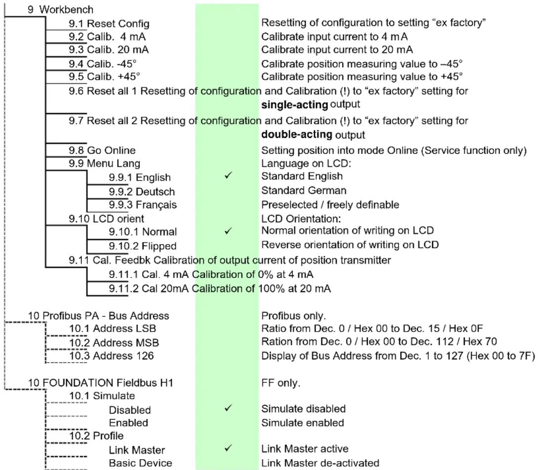
tree
9 Workbench | Node | Configuration | Description | |---|---|---| | 10 Profibus PA - Bus Address | 9.1.1 Cal. 4 mA Calibration of 0% at 4 mA | Resetting of configuration to setting "ex factory" | 10.1 Address LSB | 9.11.2 Cal 20mA Calibration of 100% at 20 mA | Setting position into mode Online (Service function only) Language on LCD: | 9.9.1 English | ✓ | Standard English | 9.9.2 Deutsch | ✓ | Standard German | 9.9.3 Français | ✓ | Preselected / freely definable LCD Orientation: | 9.10 LCD orient | ✓ | Normal orientation of writing on LCD | 9.10.1 Normal | ✓ | Reverse orientation of writing on LCD | 9.10.2 Flipped | ✓ | Normal orientation of writing on LCD 9.11 Cal. Feedbk Calibration of output current of position transmitter 9.11.1 Cal. 4 mA Calibration of 0% at 4 mA 9.11.2 Cal 20mA Calibration of 100% at 20 mA | | 10 FOUNDATION Fieldbus H1 | 10.1 Simulate | Profibus only. Ratio from Dec. 0 / Hex 00 to Dec. 15 / Hex 0F Ration from Dec. 0 / Hex 00 to Dec. 112 / Hex 70 Display of Bus Address from Dec. 1 to 127 (Hex 00 to 7F) | | 10.2 Profile | Disabled | ✓ Simulate disabled Enabled | ✓ ✓ ✓ ✓ ✓ ✓ ✓ ✓ ✓ ✓ ✓ ✓ ✓ ✓ ✓ ✓ ✓ ✓ ✓ ✓ ✓ ✓ ✓ ✓ ✓ ✓ ✓ ✓ ✓ ✓ ✓ ✓ ✓ ✓ ✓ ✓ ✓ ✓ ✓ ✓ ✓ ✓ ✓ ✓ ✓ ✓ ✓ ✓ ✓ ✓ ✓ ✓ ✓ ✓ ✓ ✓ ✓ ✓ ✓ ✓ ✓ ✓ ✓ ✓ ✓ ✓ ✓ ✓ ✓ ✓ ✓ ✓ ✓ ✓ ✓ ✓ ✓ ✓ ✓ ✓ ✓ ✓ ✓ ✓ ✓ ✓ ✓ ✓ ✓ ✓ ✓ ✓ ✓ ✓ ✓ ✓ ✓ ✓ ✓ ✓✓ ✓✓ ✓✓ ✓✓ ✓✓ ✓✓ ✓✓ ✓✓ ✓✓ ✓✓ ✓✓ ✓✓ ✓✓ ✓✓ ✓✓ ✓✓ ✓✓ ✓✓ ✓✓ ✓✓ ✓✓ ✓✓ ✓✓ ✓✓ ✓✓ ✓✓ ✓✓ ✓✓ ✓✓ ✓✓ ✓✓ ✓✓ ✓✓ ✓✓ ✓✓ ✓✓ ✓✓ ✓✓ ✓✓ ✓✓ ✓✓ ✓✓ ✓✓ ✓✓ ✓✓ ✓✓ ✓✓ ✓✓ ✓✓ ✓✓ ✓Invensys Systems, Inc. 38 Neponset Street Foxboro, MA 02035 United States of America
schneider-electric.com
Global Customer Support Toll free: 1-866-746-6477 Global: 1-508-549-2424 Website: http://support.ips.invensys.com
Copyright 2010-2016 Invensys Systems, Inc. All rights reserved. Invensys, Foxboro, and I/A Series are trademarks of Invensys Limited, its subsidiaries, and affiliates. All other trademarks are the property of their respective owners.
natural_image
Technical line drawing of mechanical assembly components (no text or symbols)natural_image
Technical diagram of a mechanical assembly with exploded view, showing internal components and assembly steps (no text or labels)natural_image
Technical line drawing of a mechanical device with no visible text or symbolsnatural_image
Technical diagram of a mechanical assembly with exploded view and assembled view (no text or labels)natural_image
Cross-sectional diagram of a mechanical or electrical component with internal components and directional arrows (no text or symbols)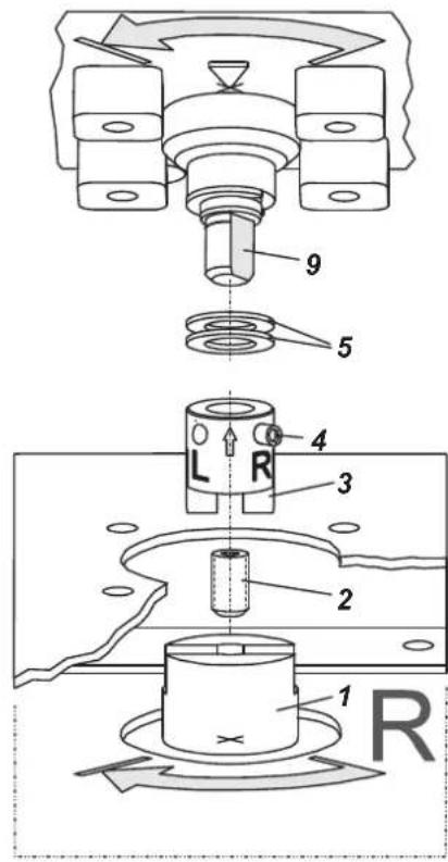
2. ANSCHLÜSSE
3.1.3 SRD991-xP (PROFIBUS PA) SRD991-xQ (FIELDBUS FF)
natural_image
Technical line drawing of mechanical assembly components (no text or symbols)natural_image
Technical line drawing of a mechanical assembly with exploded view and component detail (no text or labels)MONTAGE SUR SERVOMOTEURS LINÉAIRES (continuer)
natural_image
Technical line drawing of a mechanical valve assembly with no visible text or symbolsMONTAGE SUR SERVOMOTEURS ROTATIFS
natural_image
Technical diagram of a mechanical assembly with exploded view and internal components (no text or labels)natural_image
Cross-sectional diagram of a mechanical or electrical component with internal components and directional arrows (no text or symbols)2. RACCORDEMENTS
RACCORDEMENTS PNEUMATIQUES
ATTENTION
3.1.1 SRD991-xD (sans communication) SRD991-xH (HART)
3.1.3 SRD991-xP (PROFIBUS PA) SRD991-xQ (FIELDBUS FF)
1. MONTAGGIO SULL'ATTUATORE
natural_image
Technical line drawing of mechanical assembly components (no text or symbols)natural_image
Technical line drawing of a mechanical assembly with exploded view (no text or symbols)Montaggio diretto
natural_image
Technical line drawing of a mechanical device with no visible text or symbols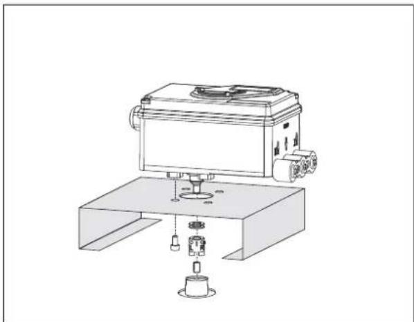
natural_image
Technical line drawing of a mechanical device with base and mounting base (no text or symbols)COLLEGAMENTI PNEUMATICI
Per SRD991-xH (HART)
Per SRD991-xE (FoxCom it1)

Segnale 4 a 20 mA
Per SRD991-xF (FoxCom it2)

Per SRD991-xQ (FOUNDATION F. H1)

Error Messages: (for more error messages see the Master Instruction at our Website)
| LEDs | Description of message / LCD text | Remedy | ||||
| M | 1 | 2 | 3 | 4 | ||
| 34 | - | - | 14 | - | I'll loop current | |
| Message 4:Input current outsideof operating range | Check nameplate (INPUT) for correct versionMessage appears at :Analog or HART: input current under approx. 3.8mA or above approx. 22 mAFieldbus or FoxCom: input current under approx.9 mA or above approx. 12 mA | check supply voltage (Analogue) orBus voltage (Fieldbus),exchange SRD if necessary | ||||
| 3/4 | 1/4 | - | 1/4 | - | Pot problem | |
| Message 5: Position sensor | Position sensor input recognizes error | check 3-pole plug at electronic board | ||||
| check cable to sensor | ||||||
| check sensor (Potentiometer: 5k +20% -0%) | ||||||
| Position not within permissible rotation angle range. Lower deviation of the original 0% and exceeding of the original 100%, which have been determined by Autostart. | Check feedback lever mounting (flat area points to arrow on housing) | |||||
| During Autostart a change of the direction of movement was found | Acknowledge via key (√), then o.k. | |||||
| Check further possible reasons: valve seat worn-out; spindle lock out-of-line; carrier unit on spindle lock is damaged (for determination of valve position). | ||||||
| 3/4 | 1/4 | 1/4 | 1/4 | - | No supply press | |
| Message 7:Air supply /pneumatic error | Detection:spring closes: w >2 %, but position < 1 %spring opens: w < 98 %, but position > 99 %without spring:no actuator change in direction of position signal | check air supply pressure | ||||
| lead cable separated | ||||||
| possibly poor control parameters are set | ||||||
| pneumatic parts blocked | ||||||
| 3/4 | - | - | - | 1/4 | Autostart err 1 | |
| Message 8: AUTOSTART defective | Air supply too low | Check air supply | ||||
| Feedback lever (linear actuator) or Coupling (rotary actuator) incorrectly linked. Potentiometer moves out of operating range of ±47% of 0° position | Check mounting.Flat area points to arrow on housing | |||||
| Coupling (rotary actuator) incorrectly linked (R and L interchanged) | Check mounting | |||||
| Pneumatic output to actuator closed or untight/When direct mounting onto FlowTop or FlowPak, the screw plug y1-d is not removed. | Check pneumatic connections | |||||
| Mechanical stops not determinable | Check spring movement of actuator / check air supply / Check mounting | |||||
| When using a booster or spool valve, no control parameters can be determined, since air capacity is too high. | Device version is not suitable for this actuator; select version with smaller air capacity or remove booster. | |||||
| Control parameter too high since air capacity is too high (in general, oscillation in valve movement) | Use a booster or the version with spool valve. Reduce control parameter prop.-gain (Menu 6.1 and 6.2) to Code 10 = value 26.6. | |||||
| Possibly incomprehensible configuration data | Reset configuration, see Menu 9.1 | |||||
| M | 1 | 2 | 3 | 4 | |
| 34 | 14 | - | - | 14 | |
| Autostart err 2 | |||||
| Message 9: AUTOSTART defective | Configuration to single-acting instead of double-acting actuator | Initialize factory calibration for double-acting in Menu 9.7 | |||
| 3/4 | 1/4 | 1/4 | - | 1/4 | Ctrl diff error | |
| Message 11:Remaining control deviation | Actuator problems (high friction or blocked) | Check actuator | ||||
| Insufficient air supply | Check air supply / air filter | |||||
| Insufficient parameters for position controls,for example, amplification too small | Check control paramter,check pneumatic components | |||||
| IP module or pneumatic amplifier defect | Check in Menu 7; replace if necessary | |||||
Diagnosis without LED or LCD inform:
| Fault | Possible cause | Solution |
| Positioner not operational using key pads | No input signal at 11, 12 | Connect input signal |
| Local operation blocked (write protection) | Remove blockage via communication | |
| No automatic power up (Reset) | Reset SRD with keys | |
| A key got jammed | Release cover screws, check menu functions, retighten cover | |
| Failure in the positioner | send device to manufacturer | |
| Autostart not completed (>45 min) | Actuator volume too large | stop Autostart and carry out extended Autostart, see chapter 8.3, Menu 2 or apply booster |
| Failure in the positioner, otherwise Message 8, 9 | carry out Autostart again, see chapter. 8.1 and 8.3, Menu 2 carry out Reset configuration | |
| send device to manufacturer | ||
| Autostart remains stagnant for a longer time (>10 min) in step 1 or 2 (LED 1 or 2 lights up), otherwise message 8 | Feedback lever (at stroke actuator) incorrectly mounted. Verify installation of feedback lever, see chapt. 4; flat part points to arrow on housing | |
| Coupling piece (at rotary actuator) incorrectly turned (R and L mixed up): Verify direction of rotation, see chapt. 4; flat part points to arrow on housing | ||
| Autostart remains stagnant for a longer time (>10 min) in step 3 (LCD: shows"Control params") (LED: #3 lights up) | At large volume actuators the Autostart can possibly remain stagnant for a longer time (>10 min) in step 3, prior to continuing in step 4 | |
| Actuator does not react to a change in the input signal | No Autostart performed. | Perform Autostart. |
| Positioner is not IN OPERATION | Switch positioner IN OPERATION, see chap. 8.2 resp. Autostart or via Configurator | |
| Setpoint source is configured wrong | Correct configuration via configurator | |
| Actuator does not attain the closed or opened position | Autostart not carried out | carry out Autostart |
| Supply pressure too low | check supply air pressure | |
| Travel limit is set Message 12, 13 | check settings, see chapter 8.3, Menu 5 | |
| Angle position linearization, positioner action or characteristic curve is set incorrectly (e.g. 'Custom', but values are missing) | check settings, see chapter 8.3, Menus 1, 3, 4 | |
| Unstable behaviour, position control circuit oscillates | Autostart incomplete, therefore, control parameters not suitable | carry out complete Autostart, see chapter 8.3, Menu 2 |
| Small actuator volume but high air capacity | increase damping at pneumatic output, see chapter 8.3, Menu 8 | |
| Friction on valve packing too great | loosen packing gland slightly or replace | |
| IP module or Pneumatic amplifier defective | change module, see page 47 | |
| Actuator reacts too sluggish | air capacity insufficient | attach booster |
| damping set too high | reduce damping at pneumatic output, see chapter 8.3, Menu 8 | |
| positioning time T63 set too high | reduce positioning time, see chapter 8.3, Menu 6 | |
| No communication possible | Input voltage too low | Eliminate voltage drop |
| Faulty protocol, communicator and device type do not match | Check configuration of devices | |
| Wrong elektronics unit | change device |