
TeSys Ultra TCSEQM113M13M - Industrial network interface SCHNEIDER - Free user manual and instructions
Find the device manual for free TeSys Ultra TCSEQM113M13M SCHNEIDER in PDF.

| Product Type | Industrial Network Interface (Modbus/TCP gateway module) |
| Brand | Schneider (Telemecanique) |
| Model | TeSys Ultra TCSEQM113M13M |
| Power Supply | +24 V DC nominal, tolerance +19.2 to +31.2 V DC |
| Maximum Consumption | 42 mA at 24 V DC |
| Network Protocols | Ethernet Modbus/TCP and RS-485 Modbus RTU |
| Number of Simultaneous Connections | 6 Modbus/TCP connections |
| Ethernet Speed | 10/100 Mbit/s, half-duplex only |
| Auto-negotiation | Yes, with auto-MDI/MDI-X |
| Serial Interface | 1 RJ-45 RS-485 port (shielded, max 3 m) |
| LED Indicators | 5 LEDs: SER ACT (yellow), STATUS (green), LINK (green), 100MB (green), ETH ACT (green) |
| Mounting | DIN Rail |
| Operating Temperature | 0 to 60 °C |
| Storage Temperature | -40 to +85 °C |
| Relative Humidity | 95 % RH at 60 °C (operation) |
| Protection Rating | IP20 (EN 61131-2) |
| Certifications | UL 508, CSA 142, CE, EN 61131-2, EN 55011 Class A |
| Compliance | RoHS, WEEE |
| Safety | Class I, Division 2, Groups A, B, C, D |
| Maintenance | Follow the safety instructions in the manual; reset via Telnet if necessary |
| Cleaning | Disconnect before cleaning; use a dry non-abrasive cloth |
Frequently Asked Questions - TeSys Ultra TCSEQM113M13M SCHNEIDER
User questions about TeSys Ultra TCSEQM113M13M SCHNEIDER
0 question about this device. Answer the ones you know or ask your own.
Ask a new question about this device
Download the instructions for your Industrial network interface in PDF format for free! Find your manual TeSys Ultra TCSEQM113M13M - SCHNEIDER and take your electronic device back in hand. On this page are published all the documents necessary for the use of your device. TeSys Ultra TCSEQM113M13M by SCHNEIDER.
USER MANUAL TeSys Ultra TCSEQM113M13M SCHNEIDER
Read these instructions carefully and look at the equipment to become familiar with the device before trying to install, operate, or maintain it. The following special messages may appear throughout this documentation or on the equipment to warn of potential hazards or to call attention to information that clarifies or simplifies a procedure.

The addition of this symbol to a Danger or Warning safety label indicates that an electrical hazard exists, which will result in personal injury if the instructions are not followed.

This is the safety alert symbol. It is used to alert you to potential personal injury hazards. Obey all safety messages that follow this symbol to avoid possible injury or death.

DANGER
DANGER indicates an imminently hazardous situation, which, if not avoided, will result in death, serious injury, or equipment damage.

WARNING
WARNING indicates a potentially hazardous situation, which, if not avoided, can result in death, serious injury, or equipment damage.

CAUTION
CAUTION indicates a potentially hazardous situation, which, if not avoided, can result in injury or equipment damage.
Please Note
Electrical equipment should be installed, operated, serviced, and maintained only by qualified personnel. No responsibility is assumed by Schneider Electric for any consequences arising out of the use of this material. This document is not intended as an instruction manual for untrained persons.
© 2007 Schneider Electric. All rights reserved.
Packaging Description
The ConneXium TeSysPort TCSEQM113M13M package contains:
• TCSEQM113M13M TeSysPort
- Quick Reference Guide (this book)
Introduction
Summary
The ConneXium TeSysPort adds Ethernet connectivity to Telemecanique's TeSys product line. It is the interface device between a single TeSys Modbus/RTU (RS-485) device and the physical layer of Modbus/TCP networks in slave mode. TeSysPort requires a separate power supply. An Ethernet device connected to the TeSysPort is the client/master. A Modbus device, such as TeSys U or TeSys T, connected to the TeSysPort is the server/slave. Any requests from an Ethernet device are sent to the TeSys U and TeSys T devices transparently.
About TeSys Motor Management System
TeSys Motor Management System includes 2 different solutions:
- The TeSys T Motor Management System is an intelligent motor protection relay (IMPR) that provides current-related protections, and has 6 inputs and 4 outputs, as well as an extension module, which extends the functionality of the IMPR by adding voltage-related protection and 4 additional inputs. The TeSys T Motor Management System offers protection, control, and monitoring capabilities for single-phase and 3-phase induction motors. The current range covered is 0.4 to 100 A with internal current transformer and 100 to 810 A with external current transformer.
- TeSys U Motor Starter is a modular, intelligent motor starter that provides power control and current-related protections. Up to 15 kW circuit breaker and contactor are integrated inside the TeSys U starter controller. Above 15 Kw to 450 kW circuit breaker and contactor are external to the TeSys U controller.
About Modbus
The Modbus protocol is a master/slave protocol that allows one master to request responses from slaves or to take action based on their requests. The master can address individual slaves or can initiate a broadcast message to all slaves. Slaves return a message (response) to queries that are addressed to them individually.
Responses are not returned to broadcast queries from the master.
About Modbus/TCP Communications
TeSysPort supports up to 6 simultaneous Modbus/TCP connections. Attempting to use more than 6 connections results in a degradation of performance because TeSysPort closes the connection with the longest idle time to accept a new connection request.
Note:
If your system uses an NOE module, use NOE firmware version 3.5 or higher.
If your system uses an ETY module, use ETY firmware version 3.1 or higher.
If your system uses a Unity-compatible CPU with an integrated Ethernet port, use CPU firmware version 2.0 or higher.
If Powersuite is used for configuration over Ethernet, the minimum revision should be version 2.4.
The TeSysPort Module External Features
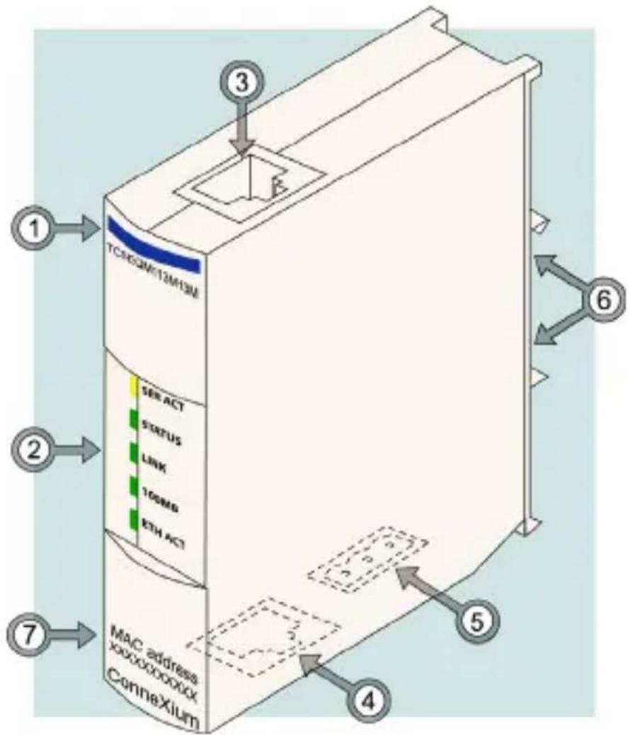
| Feature Function | ||
| 1 | Model name TCSEQM113M13M | |
| 2 | LED display visual indications of TeSysPort's operating status | |
| 3 | RJ-45 modular jack | communications connection to TeSysPort' RS-485 port (cable not supplied)Note: The RS-485 cable must not be greater than 3 m.Note: All communication cables must be shielded for optimal performance. |
| 4 | RJ-45 modular jack | connection to TCP/IP over Ethernet cable (not supplied) |
| 5 | power terminal | power input using 3-position open style connector (connector included) |
| 6 | DIN rail connector | for DIN rail mounting |
| 7 | MAC address indicates MAC address | |
System Overview
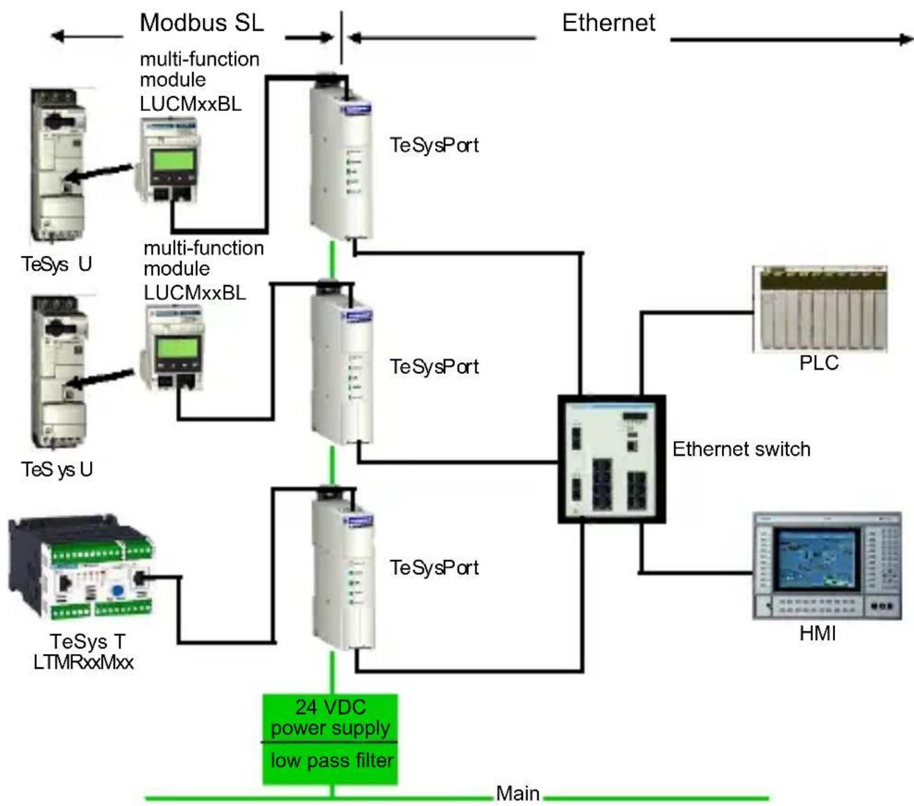
System Diagram
The TeSysPort module provides Ethernet communications through its RS485 connection to any TeSys T or TeSys U model capable of providing Modbus communications. The following diagram shows the TeSysPort module installed in a system, providing Ethernet communications to TeSys U models. For further information on the TeSys family of modules, consult the TeSys T and TeSys U user documentation.
flowchart
graph TD
    A["Modbus SL"] --> B["TeSys U"]
    A --> C["TeSys U"]
    A --> D["TeSys T LTMRxxMxx"]
    B --> E["multi-function module LUCMxxBL"]
    C --> F["multi-function module LUCMxxBL"]
    D --> G["24 VDC power supply low pass filter"]
    H["Ethernet"] --> I["TeSys Port"]
    I --> J["TeSys Port"]
    J --> K["Ethernet switch"]
    K --> L["PLC"]
    K --> M["HMI"]
    N["Main"] --> A
    style A fill:#f9f,stroke:#333
    style B fill:#ccf,stroke:#333
    style C fill:#ccf,stroke:#333
    style D fill:#ccf,stroke:#333
    style E fill:#cfc,stroke:#333
    style F fill:#cfc,stroke:#333
    style G fill:#cfc,stroke:#333
    style H fill:#fcc,stroke:#333
    style I fill:#ffc,stroke:#333
    style J fill:#ffc,stroke:#333
    style K fill:#ffc,stroke:#333
    style L fill:#fcc,stroke:#333
    style M fill:#fcc,stroke:#333
Note: The TeSysPort module is suitable for use in either:
• class 1, division 2, groups A, B, C, D
- or -
• non-hazardous locations

WARNING
EXPLOSION HAZARD
Do not substitute components, which may impair suitability for class 1, division 2.
Failure to follow this instruction can result in death, serious injury, or equipment damage.

WARNING
EXPLOSION HAZARD
Do not disconnect equipment unless power has been switched off or the area is known to be non-hazardous.
Failure to follow this instruction can result in death, serious injury, or equipment damage.

WARNING
HAZARD OF ELECTRIC SHOCK OR BURN
Connect the ground wire to the PE terminal before you establish any further connections. When you remove connections, disconnect the ground wire last.
Failure to follow this instruction can result in death, serious injury, or equipment damage.
Class 1, Division 2 Wiring Notes
Note: Power, input, and output (I/O) wiring must be in accordance with Class I, Division 2 wiring methods [Article 501-4(b) of the National Electrical Code, NFPA 70] and the authority having jurisdiction.
Note: Use 60/75 or 75 °C copper (CU) wire only.
Note: Peripheral equipment must be suitable for the location in which it is used.
Features
Auto-negotiation
TeSysPort supports 10/100TX auto-negotiation. It communicates only in half-duplex mode.
Auto-MDI/MDI-X
TeSysPort supports auto-switching of transmit and receive wire pairs to establish communications with the end device (auto-MDI/MDI-X). TeSysPort, therefore, transparently interconnects infrastructure or end devices with either straight-through or crossover cables.
LED Physical Description Introduction
The five LEDs implemented in TeSysPort are visual indications of the operating status of the module:
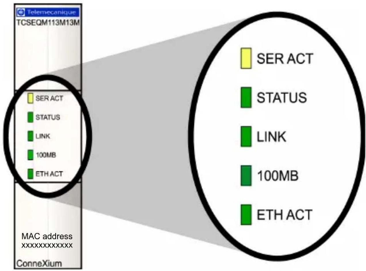
TeSysPort Communication LEDs
This table describes the condition(s), colors, and blink patterns that indicate the operating status of the module:
| Label Meaning | ing Pattern Indication(s) | ||
| SER ACT (yellow) | serial active on serial activity | ||
| STATUS (green) | module status | on normal condition | |
| off abnormal condition | |||
| blink: 4 duplicate IP connection | |||
| blink: 5 attempting to get IP condition through BootP | |||
| blink: 6 default IP condition | |||
| blink: 7 kernel mode | |||
| LINK (green) | Ethernet link on link is active | ||
| 100MB (green) | speed | on | 100 MB/sec(half duplex only, no full duplex support) |
| off | 10 MB/sec(half duplex only, no full duplex support) | ||
| ETH ACT (green) | Ethernet activity | on Ethernet is active | |
| off Ethernet is not active | |||
Note : During the autobaud process, the serial activity LED blinks at a 50Hz rate and appears to be on solid. When the serial activity LED goes off, the autobaud process is complete.
Using the LED Table
Individual blinks are approximately 200 ms. There is a one-second interval between blink sequences. For example:
- blinking—blinks steadily, alternating between 200 ms on and 200 ms off
- blink 1—blinks once (200 ms), then 1 second off
- blink 4—blinks four times (200 ms on, 200 ms off, 200 ms on, 200 ms off, 200 ms on, 200 ms off, 200 ms on), then one second off
Wiring
Ethernet Wiring
TeSysPort contains an RJ-45 10/100 Mbps port. The port negotiates speed to the fastest condition that the end device can support.
Ethernet Cable Selection
| Cable Available Part Available Length (m) | ||
| EIA/TIA 568 standard shielded twisted pair cables, RJ-45 termination | 490 NTW 000 •• •= 02, 05, 12, 40, 80 | |
| UL and CSA 22.1 approved shielded twisted pair cables, RJ-45 termination | 490 NTW 000 ••U ••= 02, 05, 12, 40, 80 | |
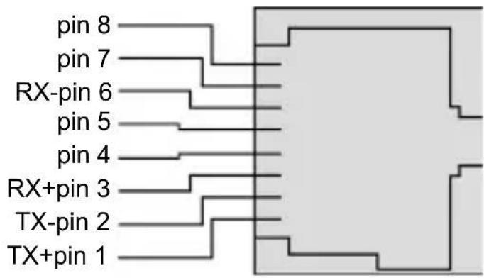
Ethernet Connector Pin Assignment
The following figure illustrates the pin assignment for TeSysPort's Ethernet port:
Modbus RS-485 Wiring
Characteristics of the RS-485 serial communication port using an RJ45 connector:
| Electrical Interface | RS-485 | |
| Connector RJ-45 | ||
| Connector Pin-out RJ-45 | Male connector, top view | |
| D(A) 5 | ||
| D(B) 4 | ||
| TESTAL 3 | ||
| Common Ground 8 | ||
| Common Ground 6 | ||
Modbus Cable Selection
| Cable Available Part Available Length | ||
| 2 RJ-45 connectors | VW3 A8 306 R10 1 m | (3.2 ft) |
| VW3 A8 306 R30 3 m | (9.8 ft) | |
Power Wiring
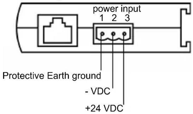
power connector
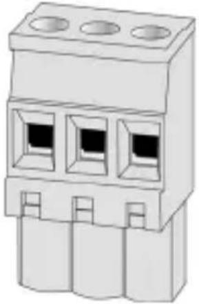
natural_image
Illustration of a three-pin electrical connector (no text or symbols)Note: PE wire must be at least 16 AWG.
Theory of Operations
Overview
Modbus/TCP clients can communicate with TeSys through TeSysPort, a bridge between TeSys devices (Modbus/RTU over RS-485 serial link) and Modbus/TCP over Ethernet networks.
Note: When implementing TeSysPort on a network, the system design requirements must account for the inherent limited bandwidth of serial connections. Expect a typical performance of approximately 10 Modbus transactions per second. Requesting multiple registers in a single request is more efficient than placing a separate request for each register.
You can not initiate read or write requests from the TeSys module through TeSysPort.
Mounting
To connect TeSysPort to the DIN rail, follow the steps below (as shown in the diagram below):
| Step Action Comment | |
| 1 Attach the hinges on the back of the TeSysPort to the DIN rail, then press down to align TeSysPort vertically with the rail. | Make sure the DIN rail latch is pulled down to the open position. |
| 2 Lock TeSysPort to the DIN rail. Push up the plastic DIN rail clip on the bottom. | |
The following figure shows TeSysPort being mounted on a DIN rail:
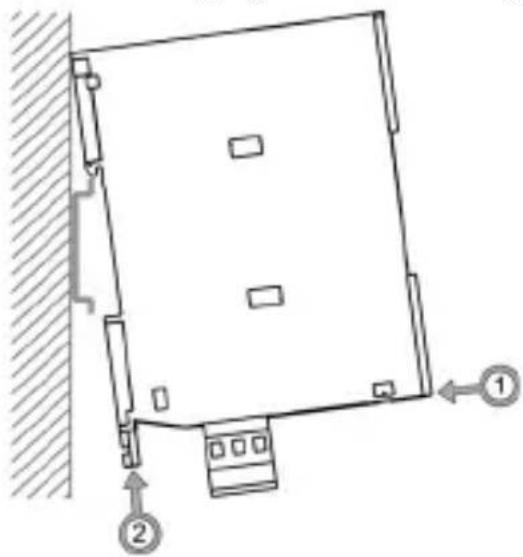
natural_image
Diagram of a square-shaped structure with two numbered components and directional arrows, no text or symbols present.Note : Before installing a TeSysPort product, read the safety information contained within this book.
English
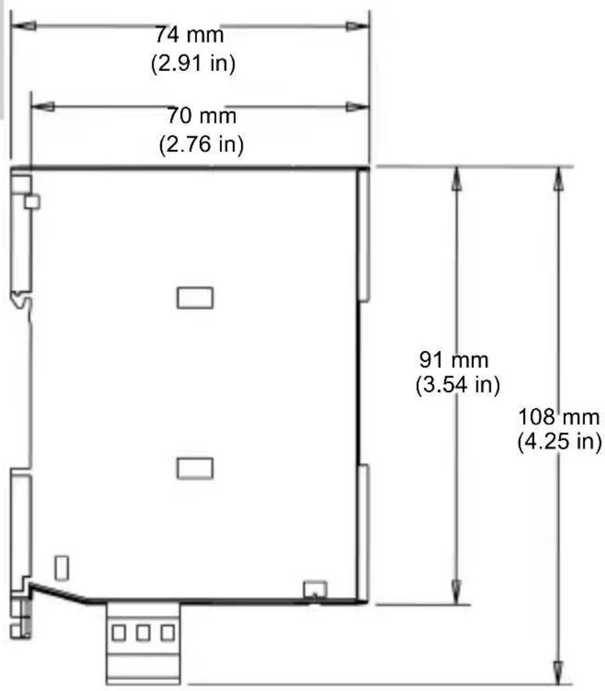
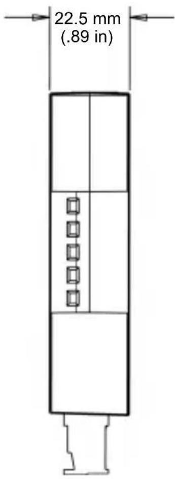
TeSysPort Dimensions
Configuration: Connections
| Step Action | ||
| 1 Attach a 3-position open style connector to the power connector on the bottom of the TeSysPort, which provides +24VDC and PE. | ||
| 2 Connect the Modbus cable* to the connecting device's serial port. | Top plug: from TeSys (serial) | |
| 3 Connect the RJ-45 plug from a standard Ethernet network cable* to TeSysPort's Ethernet port. | 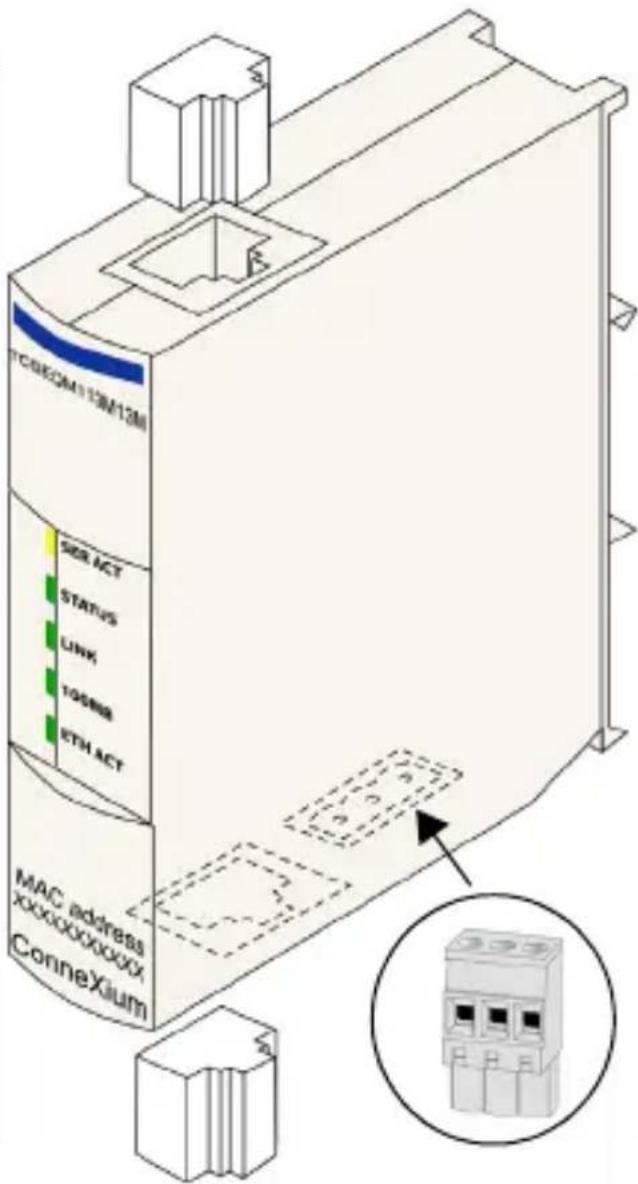 | |
| * Cable not supplied. | Bottom plug: from Ethernet, either a straight or crossover cable | |
| Note 1: TeSysPort requires a power source with a voltage range of +19.2 VDC to +30 VDC. The power connector accepts wire between 16 and 24 AWG. | ||
| Note 2: Any RS-485 Modbus port on TeSys can be used. | ||
Configuration: Default IP
TeSysPort expects a response from the BootP server within two minutes of its BootP request transmission. Failing that, TeSysPort assumes the default IP configuration that is constructed from a MAC address of this structure:
| 85 | 16 | MAC[4] | MAC[5] |
The MAC Address has the structure: MAC[0] MAC[1] MAC[2] MAC[3] MAC[4] MAC[5]. For example, if the MAC address is 0080F4012C71, the default IP address would be the decimal representation of the MAC address (85.16.44.113).
Configuration: Telnet Configuration
Configure TeSysPort with a Telnet session (using a VT100-compatible Telnet client) when the BootP request is not answered after 2 minutes (resulting in the implementation of the default IP address).
Note: While configuring TeSysPort with Telnet, make sure that Telnet's local echo is set to off. (Typical Telnet clients have local echo turned on, which results in typed characters appearing twice.)
To use Telnet, add TeSysPort's default IP address to the PC's routing table using the command:
C:> route add 85.0.0.0 mask 255.0.0.0
local_IP_address_of_PC
For example, if the IP address of the PC is 192.168.10.30 and the default IP address of TeSysPort is 85.16.44.113, the complete command would be:
C:> route add 85.0.0.0 mask 255.0.0.0 192.168.10.30
Telnet Main Menu
When you start a Telnet session (e.g., by typing telnet 85.16.44.113 at a command prompt or by using Windows ^TM Hyperterminal ^TM ), the Telnet main menu appears after you press Enter.
Telenecanique TeSysPort Configuration and Diagnostics
(c) 2007 Schneider Automation Inc

1) IP/Ethernet Settings
    IP Source: STORED
    IP Address: 192.168.2.110
    Default Gateway: 192.168.2.110
    Netmask: 255.255.255.0
    Ethernet Frame Type: ETHERNETII

2) Serial Configuration
    Baud Rate: 19200
    Data Bits: 8
    Parity: EUEN
    Stop Bits: 1
    Protocol: RTU

3) Gateway Configuration
    Slave Address Source: UNIT_ID
    Slave Address: 20
    MB Broadcasts: DISABLED

4) Security Configuration

5) Ethernet Statistics

6) Serial Statistics

7) Serial Autoboud Configuration

Commands: Ddefault settings, S)ave, F)irmware Upgrade, Q)uit without save Select Command or Parameter(1..7) to change:
IP/Ethernet Settings
Use the following instructions to change the IP/Ethernet settings:
| Step | Action Comment | |
| 1 | Start a Telnet session. Use the instructions above to open the Telnet main menu. | |
| 2 | Select (type) 1 to change the IP source to STORED and press Enter. | STORED may already be the IP source. |
| 3 | Set desired IP parameters manually. (See TeSysPort Ethernet settings following this table.) | Other parameters include:IP AddressDefault GatewayNetmaskEthernet Frame Type |
| 4 | Select R and press Enter. | The Telnet main menu appears. (You may have to press Enter again to update the screen.) |
The selected IP source option dictates the location from which the IP configuration is obtained:
- STORED—from local flash memory
• SERVED—from BootP server
The default IP address (DEFAULT) is derived from the MAC address. (By definition, the default is not selectable.)
TeSysPort Ethernet settings:
Telemecanique TeSysPort Configuration and Diagnostics (c) 2007 Schneider Automation Inc
IP/Ethernet Settings
1>IP Source: DEFAULT
2)IP Address: 85.16.147.126
3>Default Gateway: 85.16.147.126
4)Netmask: 255.0.0.0
5) Ethernet Frame Type: ETHERNET2
Commands: R>return to Main Menu Select Command or Parameter(1..4) to change:
Serial Parameter Configuration
Note : Under most circumstances, it is not necessary to configure TeSysPort's serial parameters. TeSysPort's default Modbus parameters are 19200-8-E-1.
To configure TeSysPort's serial parameters:
| Step A | Action Comment | |
| 1 S | Start a Telnet session. Use the instructions above to open the Telnet main menu. | |
| 2 S | Select (type) 2 to change the serial settings. | See the following figure. |
| 3 V | Verify or reset the settings. Other parameters include:• Baud Rate• Data Bits• Parity• Stop Bits• Protocol | |
| 4 | Select R and press Enter. | The Telnet main menu appears.(You may have to press Enter again to update the screen.) |
TeSysPort's serial settings:
Telenecanique TeSysPort Configuration and Diagnostics (c) 2007 Schneider Automation Inc
Serial Configuration 1) Baud Rate: 19200 2) Data Bits: 8 3) Parity: EUEN 4) Stop Bits: 1 Protocol: RTU
Commands: R) return to Main Menu Select Command or Parameter(1..4) to change: _
Configuring the Gateway
Note: Usually, it is not necessary to configure TeSysPort's gateway parameters.
| Step | Action Comment | ||
| 1 | Start a Telnet session. Use the instructions above to open the Telnet main menu. | ||
| 2 | Select (type) 3 to change the gateway parameters. | See the following figure. | |
| 3 | The following gateway parameters are available: | ||
| (1) slave address source | FIXED | If the slave address is FIXED, set it to the value of the TeSys module's Modbus address. Valid addresses are in the 1 to 247 range. | |
| UNIT_ID | The unit ID of the Modbus/TCP frame will be used. | ||
| (2) slave address | 20 | Modbus device address | |
| (3) MB broadcasts DISABLED | No broadcast messages are sent on TeSysPort's serial port. | ||
| ENABLED | Broadcast messages are sent from the TeSys module's serial port. | ||
| 4 | Select R and press Enter. | The Telnet main menu appears. (You may have to press Enter again to update the screen.) | |
TeSysPort gateway settings:
Telemecanique TeSysPort Configuration and Diagnostics (c) 2007 Schneider Automation Inc
Gateway Configuration
1) Slave Address Source: UNIT_ID
2) Slave Address: 20
3) MB Broadcasts: DISABLED
Commands: R>return to Main Menu
Select Command or Parameter(1..4) to change:
Security Configuration
Use the following instructions to change the default password:
| Step A | Action Comment | |
| 1 S | Start a Telnet session. Use the instructions above to open the Telnet main menu. | |
| 2 | Select (type) 4 and press Enter. | The Security Configuration Screen appears. |
| 3 | Select C and press Enter. | |
| 4 E | Enter the old password. Authorized users will know the old password (default is USERUSER). | |
| 5 E | Enter a new password. Retype the new password. | |
| 6 E | Enter a new password again. See the note below for acceptable passwords. | |
| 7 | Select R and press Enter. | The Telnet main menu appears. (You may have to press Enter again to update the screen.) |
| Note: Password details: · minimum length: 4 characters · maximum length: 10 characters · allowed characters: 0 to 9, a to z, A to Z (no spaces) | ||
TeSysPort's Security Configuration confirmation screen:
Telemecanique TeSysPort Configuration and Diagnostics (c) 2007 Schneider Automation Inc SECURITY CONFIGURATION
Commands: C)hange Configuration Password, R)return to Main Menu.
Saving the Configuration
To save the changes to the configuration during a Telnet session:
| Step Action Comment | ||
| 1 | Select (type) S and press Enter. | |
| 2 | Enter the configuration password. | The default password is USERUSER. |
TeSysPort's Save Configuration confirmation screen:
Telenecanique TeSysPort Configuration and Diagnostics (c) 2007 Schneider Automation Inc SAVE CONFIGURATION
New Configuration was successfully stored to Flash.
Reboot your module for the new Configuration to be in effect.
Rebooting in 5 Seconds. You will lose your telnet connection.
Upgrading the TeSysPort Firmware
Note: Obtain a newer version of the TeSysPort firmware before attempting to upgrade the firmware with these instructions. Stop the process before upgrading the firmware. Modbus communication will not be available during the firmware upgrade procedure.
| Step A | Action Comment | |
| 1 | Start a Telnet session. Use the instructions above to open the Telnet main menu. | |
| 2 | Select (type) F to initiate the firmware upgrade. | Five seconds after selecting F (firmware upgrade), TeSysPort resets and the Telnet connection is lost. |
| 3 | At the command line, type: ftp and TeSysPort's IP address. | For example: ftp 192.168.1.102 |
| 4 | E n t e r ftptesysport. At the login name prompt. | |
| 5 | Enter: cd fw | This takes the user to the fw directory. |
| 6 | E n t e r : put A message indicates that the ftp was (see notes 1 and 2). | successful (see note 3). |
| Note 1: File names are case-sensitive. | ||
| Note 2: Make sure App.out is in the current working directory of the ftp client. | ||
| Note 3: A message indicates that TeSysPort will automatically reboot 5 seconds after a successful ftp. | ||
Telemecanique TeSysPort Configuration and Diagnostics
FIRMWARE UPGRADE IN-PROGRESS... Module will reboot in 5 Seconds. After Reboot, Connect via FTP to download new Firmware.
FTP Instructions: 1) Connect via FTP: ftp 192.168.1.102 2) Change to /fw directory: ftp>cd fw 3) Download new fu: ftp>put App.out
After the FTP download is complete, the nodule will reboot automatically
Rebooting now. Goodbye.
Connection to host lost.
Kernel Mode
In the absence of valid firmware, TeSysPort goes into Kernel mode. If you attempt to use Telnet to connect to TeSysPort while it is in this mode, you will see:
Telenecanique TeSysPort
Download valid Exec,App.out, or type 'EXEC' to leave kernel mode.
To exit type 'quit' 'QUIT' or control D
EXEC
Connection to host lost.
Ethernet Statistics
To view TeSysPort's Ethernet statistics:
| Step | Action Comment | |
| 1 | Start a Telnet session. Use the instructions above to open the Telnet main menu. | |
| 2 | Select (type) 5 to display the Ethernet Module Statistics screen. | See the figure that follows this table. |
| 3 | Press Enter to refresh the screen. | |
| 4 | S e l e c t C to clear press Enter. | All statistics are reset to 0. |
| 5 | Select R and press Enter. | The Telnet main menu appears. (You may have to press Enter again to update the screen.) |
The module's Ethernet module statistics:
| Telenecanique TeSysPort Configuration and Diagnostics (c) 2007 Schneider Automation Inc ETHERNET MODULE STATISTICS | ||
| Status: 0x9483 System Log Entry: No Transnit Speed: 100BASE-T Full/Half Duplex: Half Duplex | IP Address: 192.168.1.102 Mac Address: 0:80:f4:12:93:7e Subnet Mask: 255.255.255.0 Gateway Address: 192.168.1.102 | |
| Transnit Statistics | Receive Statistics | Functioning Errors |
| Transnits: 94 Transnit Retries: 0 Last Carrier: 0 Late Collision: 0 Tx Buffer Errors: 0 SILO Underflow: 0 | Receives: 52 Framing Errors: 0 Overflow Errors: 0 CRC Errors: 0 Rx Buffer Errors: 0 | Missed Packets: 0 Collision Errors: 0 Transmit Tincouts: 0 Memory Errors: 0 Net Interface Restarts: 0 |
| Broadcast Packets Received: 0 Multicast Packets Received: 0 | ||
| Commands: [Enter] to Refresh, C)lear Statistics, R)eturn to Main Menu | ||
Serial Statistics
To view TeSysPort's serial statistics:
| Step | Action Comment | |
| 1 | Start a Telnet session. Use the instructions above to open the Telnet main menu . | |
| 2 | Select (type) 6 to display the Serial Statistics screen and press Enter. | See the figure that follows this table. The serial statistics are updated. |
| 3 | S e l e c t C to clear press Enter. | Statistics are reset to 0. |
| 4 | Select R and press Enter. | The Telnet main menu appears. (You may have to press Enter again to update the screen.) |
TeSysPort's serial statistics:
Telemecanique TeSysPort Configuration and Diagnostics (c) 2007 Schneider Automation Inc
SERIAL STATISTICS
Serial Bus Statistics Bus Message Count: 2 Bus Conn. Error Count: 0 Modbus Slave Statistics Slave Message Count: 1 Slave Exception Error Count: 0 Slave No Response Count: 0
Commands: [Enter] to Refresh, C)lear Statistics, R)return to Main Menu
Enable or Disable Autobaud
To enable or disable autobaud:
| Step | Action Comment | |
| 1 | Start a Telnet session. Use the instructions above to open the Telnet main menu . | |
| 2 | Select (type) 7 to display the Autobaud Setting screen and press Enter. | See the figure that follows this table. |
| 3 | • Select 1 to enable autobaud.- or -• Select 2 to disable autobaud.• Press Enter. | Autobaud is enabled or disabled. |
TeSysPort's autobaud settings:
Telenecanique IeSysPort Configuration and Diagnostics (c) 2007 Schneider Automation Inc
-Autobaud Setting
- Enable Autobaud.
- Disable Autobaud.
Commands: [Enter] to Refresh, R>return to Main Menu, or Parameter(1..2) to change:
Restoring Factory Default Settings
To restore TeSysPort's factory default settings:
| Step A | Action Comment | |
| 1 | Start a Telnet session. Use the instructions above to open the Telnet main menu. | |
| 2 | S e l e c t D to display the default that follows this table. Settings screen. | |
| 3 | Press Enter. | Pressing Enter is required to display the main menu. |
| 4 | Save the default configuration. | See Saving the Configuration, above. |
The TeSysPort's default settings:
Ielemecanique TeSysPort Configuration and Diagnostics (c) 2007 Schneider Automation Inc DEFAULT CONFIGURATION
IP Address: BOOTP then 85.16.182.6
Gateway Address: 85.16.182.6
Subnet Mask: 255.0.0.0
Frame Type: Ethernet II
Serial Mode: 19200-8-E-1
Broadcasts Disabled, Slave Address Source=Unit ID
Configuration Password: USERUSER
You must ave the configuration to make it active.
Hit Enter to refresh and return to the Main Menu._
Forget Your Password and/or IP Configuration?
Use these instructions to connect to TeSysPort in backup mode.
Note: Make sure the unit is not powered.
| Step Action Comment | ||
| 1 Connect pin 3 (TESTAL) to pin 6 (ground) of the serial connector. | ||
| 2 Power up the unit. | ||
| 3 Connect via ftp to TeSysPort (see note). | TeSysPort uses the following IP configuration:-IP address: 192.168.2.102-subnet mask: 255.255.0.0-gateway: 192.168.2.102-frame type: Ethernet II | |
| 4 | G e t fw/Conf.dat. Obtain the | IP configuration and password from the Conf.dat file. |
| 5 O | pen the Conf.dat file in a text editor. | |
| Note: No password is required. | ||
The following illustration shows how to connect to TeSysPort via ftp in backup mode.
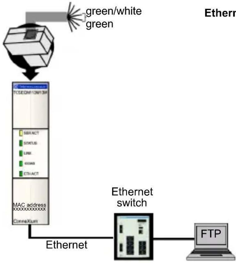
flowchart
graph TD
    A["Router"] -->|green/white green| B["TCSEQIM 13AH13A"]
    B --> C["SIBRACT"]
    C --> D["STATUS"]
    D --> E["LINK"]
    E --> F["CONN0"]
    F --> G["ETHACT"]
    G --> H["MAC address xxxxxxxxxxxx"]
    H --> I["ConnaXum"]
    I --> J["Ethernet switch"]
    J --> K["FTP"]
    style A fill:#f9f,stroke:#333
    style K fill:#ccf,stroke:#333
Locally Supported Modbus Function Codes
TeSysPort answers the following locally supported Modbus function codes only when the unit ID is set to 255. (Locally supported function codes are those answered directly by TeSysPort and not by the TeSys module.)
| ModbusFunction Code | SubfunctionCode OPCODE | Description | |
| 8 0 N/A return query data | |||
| 8 10 N/A clear counters | |||
| 8 11 N/A return bus message count | |||
| 8 12 N/A return bus comm. error count | |||
| 8 13 N/A return bus exception error count | |||
| 8 14 N/A return slave message count | |||
| 8 15 N/A return slave no response count | |||
| 8 21 3 get Ethernet statistics | |||
| 8 21 4 clear Ethernet statistics | |||
| 43 14 N/A read device ID (note 1) | |||
| Note 1: TeSysPort supports only the basic object IDs of the read device identification function code with both stream and individual access. See the Modbus specification at www.modbus.org for details on message formats and access classes. | |||
General Specifications
| Environmental Parameter | Reference Specification | |
| protection EN61131-2 | P20 | |
| safety | EN61131-2UL 508CSA 14UL Class I Div 2CE | |
| protection class EN611 | 31-2 Class 1 | |
| operating temperature | 0 to 60 degrees C | |
| storage temperature -40 | degrees C to +85 | degrees C |
| vibration - sinusoidal IE | C68, part 2-6EN61131-2 | • 5 Hz to 9 Hz with 3.5 mm displacement• 9 Hz to 150 Hz with 1 g constant acceleration |
| shock IEC68, part 2-27 | EN61131-2 | 15g for 11 ms, 3 shocks per axis |
| altitude EN61131-2 operation: | 0 to 2,000 | m (0 to 6,565 ft)transport: 0 to 3,000 m (0 to 9,842 ft) |
| free fall EN61131-2 1m | in packaging, 5 tests | |
| humidity | IDS3000 operating | 95% RH at 60 degrees C,96 hoursnon-operating: 95% RH at 60 degrees C,24 hours |
| Power Requirements Specified Value | |
| max. current draw 42 mA @ 24 VDC | |
| supply voltage | +24 VDC nominal |
| supply tolerance | +19.2 VDC to +31.2 VDC |
Note: The unit is internally fused and not user-replaceable.
| Agency Certification | |
| UL 508, UL 1604 hazardous class 1, Div. 2, groups A, B, C, D | |
| CSA C22.2 No. 142 | |
| CE | EN 61131-2 |
| EN 55011 (class A) | |
| (IEC 61000-4-2) Electrostatic Discharge (ESD) | 6KV contact |
| 8KV air | |
| (IEC 61000-4-3) RFI Immunity (RS) | 80 MHz to 2.0 GHz 10V/m, 1 KHz 80% AM |
| (IEC 61000-4-4) Fast Transients (EFT) | comm ports +/- 1KV power ports +/- 2KV |
| (IEC 61000-4-5) surge withstand capability (transients) | 1.2 x 50 μs power 1KVCM 12Ω 0.5KV 2Ω differential mode |
| (IEC 61000-4-5) surge withstand capability (transients) | 1.2 x 50 μs shielded comm. cable 1KVCM power ports DM and CM |
| EN 61000-4-6 10Vrms 150KHz to 80 | MHz, 1 KHz 80% AM |
| flammability | connector: UL |
| enclosure: UL 94V-0 | |
| Note 1: This product complies with the RoHS (Restriction of Hazardous Substances) legislation. | |
| Note 2: This product complies with the WEEE (Waste Electrical and Electronic Equipment) legislation. | |
CE Information
This device complies with the regulations of the following European directive:
89/336/EEC
Council directive on the harmonization of the legal regulations of member states on electromagnetic compatibility (amended by Directives 91/263/EEC, 92/31/EEC, and 93/68/EEC).
natural_image
Technical line drawing of a three-pin electrical connector (no text or symbols)natural_image
Technical line drawing of a square mechanical component mounted on a vertical wall, with two numbered arrows indicating motion directions (no text or symbols present)local_IP_address_of_PC.
IP/Ethernet Settings
1>IP Source: DEFAULT
2)IP Address: 85.16.147.126
3>Default Gateway: 85.16.147.126
4>Netmask: 255.0.0.0
5) Ethernet Frame Type: ETHERNET2
Commands: R>return to Main Menu Select Command or Parameter(1..4) to change:
Serial Configuration
1) Baud Rate: 19200
2) Data Bits: 8
3) Parity: EUEN
4) Stop Bits: 1
Protocol: RTU
Commands: R>return to Main Menu
Select Command or Parameter(1..4) to change: _
Configuration de la passerelle
(c) 2007 Schneider Automation Inc
Gateway Configuration
1) Slave Address Source: UNIT_ID
2) Slave Address: 20
3) MB Broadcasts: DISABLED
Commands: R>return to Main Menu
Select Command or Parameter(1..4) to change:
Commands: C>hange Configuration Password, R>return to Main Menu.
New Configuration was successfully stored to Flash. Reboot your module for the new Configuration to be in effect. Rebooting in 5 Seconds. You will lose your telnet connection.
Module will reboot in 5 Seconds.
After Reboot, Connect via FTP to download new Firmware.
FTP Instructions:
1) Connect via FTP: ftp 192.168.1.102
2) Change to /fw directory: ftp>cd fw
3) Download new fu: ftp>put App.out
After the FTP download is complete, the nodule will reboot automatically
Rebooting now. Goodbye.
Connection to host lost.
Mode noyau
Connection to host lost.
| Telenecanique TeSysPort Configuration and Diagnostics (c) 2007 Schneider Automation Inc ETHERNET MODULE STATISTICS | ||
| Status: 0x9403 System Log Entry: No Transnit Speed: 100BASE-T Full/Half Duplex: Half Duplex | IP Address: 192.168.1.102 Mac Address: 0:80:F4:12:93:7e Subnet Mask: 255.255.255.0 Gateway Address: 192.168.1.102 | |
| Transnit Statistics | Receive Statistics | Functioning Errors |
| Transnits: 94 Transnit Retrics: 0 Lost Carrier: 0 Late Collision: 0 Tx Buffer Errors: 0 SILO UnderFlow: 0 | Receives: 52 Franing Errors: 0 Overflow Errors: 0 CRC Errors: 0 Rx Buffer Errors: 0 | Missed Packets: 0 Collision Errors: 0 Transmit Timeouts: 0 Memory Errors: 0 Net Interface Restarts: 0 |
| Broadcast Packets Received: 0 Multicast Packets Received: 0 | ||
| Commands: [Enter] to Refresh, C)lear Statistics, R)eturn to Main Menu | ||
Statistiques série
Serial Bus Statistics Bus Message Count: 2 Bus Conn. Error Count: 0 Modbus Slave Statistics Slave Message Count: 1 Slave Exception Error Count: 0 Slave No Response Count: 0
Commands: [Enter] to Refresh, C)lear Statistics, R)eturn to Main Menu
IP Address: BOOTP then 85.16.182.6 Gateway Address: 85.16.182.6 Subnet Mask: 255.0.0.0 Frame Type: Ethernet II
Serial Mode: 19200-8-E-1
Broadcasts Disabled, Slave Address Source=Unit ID
Configuration Password: USERUSER
You must ave the configuration to make it active.
Hit Enter to refresh and return to the Main Menu._
natural_image
Technical line drawing of a three-pin electrical connector (no text or symbols)natural_image
Technical line drawing of a mechanical assembly with labeled components (no text or symbols)Konfiguration: Anschlüsse
local_IP_address_of_PC
Telemecanique IeSysPort Configuration and Diagnostics
(c) 2007 Schneider Automation Inc

1) IP/Ethernet Settings
    IP Source: STORED
    IP Address: 192.168.2.110
    Default Gateway: 192.168.2.110
    Netmask: 255.255.255.0
    Ethernet Frame Type: ETHERNETII

2) Serial Configuration
    Baud Rate: 19200
    Data Bits: 8
    Parity: EVEN
    Stop Bits: 1
    Protocol: RTU

3) Gateway Configuration
    Slave Address Source: UNIT_ID
    Slave Address: 20
    MB Broadcasts: DISABLED

4) Security Configuration

5) Ethernet Statistics

6) Serial Statistics

7) Serial Autobaud Configuration

Commands: D>default settings, S>ave, F>irnware Upgrade, Q>uit without save
    Select Command or Parameter(1..7) to change:
IP/Ethernet Settings
1>IP Source: DEFAULT
2)IP Address: 85.16.147.126
3>Default Gateway: 85.16.147.126
4>Netmask: 255.0.0.0
5) Ethernet Frame Type: ETHERNET2
Commands: R>return to Main Menu Select Command or Parameter(1..4) to change:
Konfiguration der seriellen Parameter
Serial Configuration
1) Baud Rate: 19200
2) Data Bits: 8
3> Parity: EVEN
4) Stop Bits: 1
Protocol: RTU
Commands: R>return to Main Menu
Select Command or Parameter(1..4) to change:
Konfiguration des Gateways
1) Slave Address Source: UNIT_ID
2) Slave Address: 20
3) MB Broadcasts: DISABLED
Commands: R>return to Main Menu
Select Command or Parameter(1..4) to change:
Sicherheitskonfiguration
Connands: C)hange Configuration Password, R)eturn to Main Menu.
New Configuration was successfully stored to Flash. Reboot your module for the new Configuration to be in effect. Rebooting in 5 Seconds. You will lose your telnet connection.
Module will reboot in 5 seconds.
After Reboot, Connect via FTP to download new Firmware.
FTP Instructions:
1) Connect via FTP: ftp 192.168.1.102
2) Change to /fw directory: ftp>ed fu
3) Download new fu: ftp>put App.out
After the FTP download is complete, the nodule will reboot automatically
Rebooting now. Goodbye.
Connection to host lost.
Kernel-Modus
Connection to host lost.
| Telemecanique TeSysPort Configuration and Diagnostics (c) 2007 Schneider Automation Inc ETHERNET MODULE STATISTICS | ||
| Status: 0x9403 System Log Entry: No Transmit Speed: 100BASE-T Full/Half Duplex: Half Duplex | IP Address: 192.168.1.102 Mac Address: 0:80:f4:12:93:7e Subnet Mask: 255.255.255.0 Gateway Address: 192.168.1.102 | |
| Transmit Statistics | Receive Statistics | Functioning Errors |
| Transmits: 94 Transmit Retries: 0 Lost Carrier: 0 Late Collision: 0 Tx Buffer Errors: 0 SILO Underflow: 0 | Receives: 52 Framing Errors: 0 Overflow Errors: 0 CRC Errors: 0 Ex Buffer Errors: 0 | Missed Packets: 0 Collision Errors: 0 Transnit Tincouts: 0 Memory Errors: 0 Net Interface Restarts: 0 |
| Broadcast Packets Received: 0 Multicast Packets Received: 0 | ||
| Commands: [Enter] to Refresh, C)lear Statistics, R)eturn to Main Menu | ||
Serial Bus Statistics Bus Message Count: 2 Bus Comm. Error Count: 0 Modbus Slave Statistics Slave Message Count: 1 Slave Exception Error Count: 0 Slave No Response Count: 0
Commands: [Enter] to Refresh, C)lear Statistics, R)eturn to Main Menu
Commands: [Enter] to Refresh, R) return to Main Menu, or Parameter(1..2) to change:
IP Address: BOOTP then 85.16.182.6
Gateway Address: 85.16.182.6
Subnet Mask: 255.0.0.0
Frame Type: Ethernet II
Serial Mode: 19200-8-E-1
Broadcasts Disabled, Slave Address Source-Unit ID
Configuration Password: USERUSER
You must (S)ave the configuration to make it active.
Hit Enter to refresh and return to the Main Menu.
natural_image
Technical line drawing of a three-pin electrical connector (no text or symbols)2) Serial Configuration Baud Rate: 19200 Data Bits: 8 Parity: EUEN Stop Bits: 1 Protocol: RTU
3) Gateway Configuration Slave Address Source: UNIT_ID Slave Address: 20 MB Broadcasts: DISABLED
4) Security Configuration
5) Ethernet Statistics
6) Serial Statistics
7) Serial Autoband Configuration
Commands: D>default settings, S>ave, F>irnware Upgrade, Q>uit without save Select Command or Parameter(1..7) to change:
IP/Ethernet Settings
1>IP Source: DEFAULT
2)IP Address: 85.16.147.126
3>Default Gateway: 85.16.147.126
4)Netmask: 255.0.0.0
5) Ethernet Frame Type: ETHERNET2
Commands: R>return to Main Menu Select Command or Parameter(1..4) to change:
Serial Configuration
1> Baud Rate: 19200
2) Data Bits: 8
3) Parity: EUEN
4) Stop Bits: 1
Protocol: RTU
Commands: R>return to Main Menu
Select Command or Parameter<1..4> to change:
1) Slave Address Source: UNIT_ID
2) Slave Address: 20
3) MB Broadcasts: DISABLED
Commands: R) return to Main Menu
Select Command or Parameter(1..4) to change:
Commands: C)hange Configuration Password, R)return to Main Menu.
New Configuration was successfully stored to Flash. Reboot your module for the new Configuration to be in effect. Rebooting in 5 Seconds. You will lose your telnet connection.
Module will reboot in 5 Seconds.
After Reboot, Connect via FTP to download new Firmware.
FTP Instructions:
1) Connect via FTP: ftp 192.168.1.102
2) Change to /fw directory: ftp>cd fw
3) Download new fu: ftp>put App.out
After the FTP download is complete, the nodule will reboot automatically
Rebooting now. Goodbye.
Connection to host lost.
Modo de núcleo
Connection to host lost.
| Telenecanique TeSysPort Configuration and Diagnostics (c) 2007 Schneider Automation Inc ETHERNET MODULE STATISTICS | ||
| Status: 0x9403 System Log Entry: No Transnit Speed: 100BASE-T Full/Half Duplex: Half Duplex | IP Address: 192.168.1.102 Mac Address: 0:00:f4:12:93:7e Subnet Mask: 255.255.255.0 Gateway Address: 192.168.1.102 | |
| Transnit Statistics | Receive Statistics | Functioning Errors |
| Transnits: 94 Transnit Retries: 0 Lost Carrier: 0 Late Collision: 0 Tx Buffer Errors: 0 SILO Underflow: 0 | Receives: 52 Framing Errors: 0 Overflow Errors: 0 CRC Errors: 0 Rx Buffer Errors: 0 | Missed Packets: 0 Collision Errors: 0 Transmit Timeouts: 0 Memory Errors: 0 Net Interface Restarts: 0 |
| Broadcast Packets Received: 0 Multicast Packets Received: 0 | ||
| Commands: [Enter] to Refresh, C)lear Statistics, R)eturn to Main Menu | ||
Estadísticas serie
Serial Bus Statistics Bus Message Count: 2 Bus Conn. Error Count: 0 Modbus Slave Statistics Slave Message Count: 1 Slave Exception Error Count: 0 Slave No Response Count: 0
Commands: [Enter] to Refresh, C)lear Statistics, R)eturn to Main Menu
Commands: [Enter] to Refresh, R) return to Main Menu, or Parameter(1..2) to change:
IP Address: BOOTP then 85.16.182.6
Gateway Address: 85.16.182.6
Subnet Mask: 255.0.0.0
Frame Type: Ethernet II
Serial Mode: 19200-8-E-1
Broadcasts Disabled, Slave Address Source-Unit ID
Configuration Password: USERUSER
You must <\$>ave the configuration to make it active.
Hit Enter to refresh and return to the Main Menu._
You can download this technical publication and other technical information from our website at http://www.telemecanique.com.
Visit http://www.schneider-electric.com for your nearest Schneider Electric affiliate.
Printed in
3100746001
4/2007