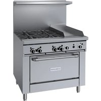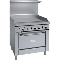
GIRCM48 - Professional cooking appliance GARLAND - Free user manual and instructions
Find the device manual for free GIRCM48 GARLAND in PDF.


User questions about GIRCM48 GARLAND
0 question about this device. Answer the ones you know or ask your own.
Ask a new question about this device
Download the instructions for your Professional cooking appliance in PDF format for free! Find your manual GIRCM48 - GARLAND and take your electronic device back in hand. On this page are published all the documents necessary for the use of your device. GIRCM48 by GARLAND.
USER MANUAL GIRCM48 GARLAND
natural_image
Exterior view of a stainless steel laboratory oven (no visible text or labels)DO NOT STORE OR USE GASOLINE OR OTHER FLAMMABLE VAPORS OR LIQUIDS IN THE VICINITY OF THIS OR ANY OTHER APPLIANCE
WARNING:
IMPROPER INSTALLATION, ADJUSTMENT, ALTERATION, SERVICE OR MAINTENANCE CAN CAUSE PROPERTY DAMAGE, INJURY, OR DEATH. READ THE INSTALLATION, OPERATING AND MAINTENANCE INSTRUCTIONS THOROUGHLY BEFORE INSTALLING OR SERVICING THIS EQUIPMENT
DO NOT OBSTRUCT THE FLOW OF COMBUSTION AND VENTILATION AIR TO THIS APPLIANCE.
PLEASE READ ALL SECTIONS OF THIS MANUAL AND RETAIN FOR FUTURE REFERENCE.
THIS PRODUCT HAS BEEN CERTIFIED AS COMMERCIAL COOKING EQUIPMENT AND MUST BE INSTALLED BY PROFESSIONAL PERSONNEL AS SPECIFIED.
IN THE COMMONWEALTH OF MASSACHUSETTS THIS PRODUCT MUST BE INSTALLED BY A LICENSED PLUMBER OR GAS FITTER.
For Your Safety:
Post in a prominent location, instructions to be followed in the event the user smells gas. This information shall be obtained by consulting your local gas supplier.
Users are cautioned that maintenance and repairs must be performed by a Garland authorized service agent using genuine Garland replacement parts. Garland will have no obligation with respect to any product that has been improperly installed, adjusted, operated or not maintained in accordance with national and local codes or installation instructions provided with the product, or any product that has its serial number defaced, obliterated or removed, or which has been modified or repaired using unauthorized parts or by unauthorized service agents. For a list of authorized service agents, please refer to the Garland web site at http://www.garland-group.com. The information contained herein, (including design and parts specifications), may be superseded and is subject to change without notice.
WARNING:
This product contains chemicals known to the State of California to cause cancer and/or birth defects or other reproductive harm. Installation and servicing of this product could expose you to airborne particles of glass wool/ceramic fibers. Inhalation of airborne particles of glass wool/ceramic fibers is known to the State of California to cause cancer. Operation of this product could expose you to carbon monoxide if not adjusted properly. Inhalation of carbon monoxide is known to the State of California to cause birth defects or other reproductive harm.
Keep appliance area free and clear of combustibles.
IMPORTANT INFORMATION....2
INTRODUCTION....4
Uncrating 4
Rating Plate 4
Statutory Regulations....4
DIMENSIONS AND SPECIFICATIONS ....5
GENERAL INFORMATION ...... 6
Cheesemelter Performance and Construction 6
INSTALLATION....6
National Code Requirements....6
Gas Connections 7
Optional Inter-Connect Kit ....8
Installation Of A Cheesemelter To A Range 9
Model GIRCM36 – 36" Ranges....9
Model GIRCM48 - 48" Ranges....10
Model GIRCM60 - 60" Ranges....12
Wall Or Counter Mounted Cheesemelters 13
Model GIRCM36C 13
Ventilation and Air Supply 14
Clearances 14
OPERATION....15
Pilot Lighting Instructions ....15
Main Burner Operation 15
Burn off Period....15
Energy Conservation 15
Shut Down Instructions ....15
Main Burner Adjustments .... 15
MAINTENANCE AND CLEANING 16
Daily 16
Monthly 16
Exterior Cleaning 16
Units included in this manual are:
Cheesemelter Models:
GIRCM36C, GIRCM36, GIRCM48, GIRCM60
All units are shipped completely assembled with the pressure regulator packed inside the unit drip tray. Units are inspected at the factory prior to shipment.
The appliance should be given regular care and maintenance. Periodic inspections by your dealer or a qualified service agency are recommended.
This product has been certified as commercial cooking equipment and must be installed by professional personnel as specified.
Uncrating
Check the crate for possible damage during transit. Carefully remove the unit from the crate and again check for damage. If damage has occurred, report it to the carrier immediately.
Shipping wire, or ties for retaining the packaging material must be removed from the units, as well as any protective material covering stainless steel.
DO NOT remove any permanently affixed label warnings or the rating plate from the appliance, as this may invalidate the manufacturer's warranty.
The type of gas and supply pressure that the equipment was set-up for at the factory are indicated on the rating plate and packaging. The type of gas and pressure specified must be supplied to the unit.
Rating Plate
The rating plate is affixed to the cheesemelter front panel and is located underneath the removable drip tray.
When corresponding with the factory or your local authorized factory service center regarding service problems or replacement parts, be sure to refer to the particular unit by the correct model number (including the prefix and suffix letters and numbers) and the warranty serial number. The rating plate contains this information.
The rating plate also contains the gas type and supply pressure, as well as listing the input rating of all burners.
In the event you have any questions concerning the installation, use, care or service of the product, write or call our Product Service Department.
Statutory Regulations
The installation of this appliance must be carried out by a competent person and in accordance with the relevant regulations, standards, codes of practice and the related publications of the Country of destination.
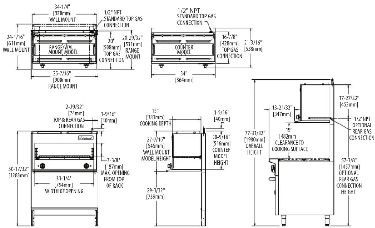
| Model Description Width | Use With G Series Model | Shipping Information | Entry Clearances | ||||
| Cu Ft | Ibs/Kg Crated | Uncrated | |||||
| GIRCM36C | Counter/Wall Mount | 34" (864mm) | N/A | 21 | 170/77 | 31" (787mm) | 21" (533mm) |
| GIRCM36 | Range Mount | 35-1/2" (900mm) | G36 | 38.2 | 200/91 | 31" (787mm) | 21" (533mm) |
| GIRCM48 | Center Mounted Cheesemelter W/Extended Flue On Both Sides | 47-1/4" (1200mm) | G48 | 60.6 | 230/105 | 31" (787mm) | 21" (533mm) |
| *GIRCM60 | Cheesemelter With 24" (610 mm) Flue Riser And Shelf | 59-1/16" (1500mm) | G60 | 60.6 | 260/118 | 31" (787mm) | 21" (533mm) |
* Note: for range models, cheesemelters are standard on right but available on the left as an option. For raised griddle/broiler models, cheesemelters are only available on left side of the range.
| Model | Combustible Clearances | Manifold Operating Pressure | Input: Natural and Propane | |||||
| Counter | For use in non-combustible locations only | Natural | Propane | Per Burner | Total | |||
| Range Mount | Sides | 6"(152mm) | Back | 6"(152mm) | 6"WC(15mbar) | 10"WC(25mbar) | 15,000 BTU/H(4.39 kW) | 30,000 BTU/H(8.79kW) |
NOTE: Installation clearance reductions are applicable only where local codes permit.
Gas input ratings shown here are for installations up to 2,000 ft. (610m) above sea level. Specify altitudes over 2,000 ft.
Garland/U.S. Range products are not approved or authorized for home or residential use, but are intended for commercial applications only. Garland / U.S. Range will not provide service, warranty, maintenance or support of any kind other than in commercial applications.
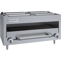
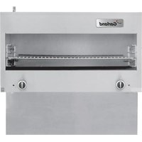
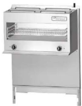
The range-mounted, gas Infra-Red cheesemelter is designed for a perfect match and fit to the Garland G series Range.
Garland products are not approved or authorized for home or residential use, but are intended for commercial applications only. Garland will not provide service, warranty, maintenance or support of any kind other than in commercial applications.
Cheesemelter Performance and Construction
Two Hi-Low gas valves provide individual control of the (2) atmospheric-type 15,000 BTU/Hr gas infra-red burners for the cheesemelter. The "LO" position is adjustable for most field gas pressure situations. Fast preheat and uniform production is provided by the high-efficiency, infra-red burners. The unique atmospheric design eliminates the need for fans and filters. Heat is directed downward onto the large heavy chrome-plated rack. Sturdy chrome-plated rack guides support the rack, and can be adjustable to four (4) positions. The rack and rack guides are easily removed for cleaning.
Models GIRCM36 and GIRCM48 cheesemelters are 36" (900mm) and 48" (1200 mm) wide respectively and are supported by heavy-formed brackets to mount to the range.
Model GIRCM60 mounts to a 60" (1500mm) wide G Series range and includes a 24" (600mm) wide shelf.
Model GIRCM36C is a counter unit and comes equipped with 4" (102mm) stainless steel legs, it may be mounted to a wall with an optional wall mounting kit.
All cheesemelter models have a stainless steel top and sides. Stainless steel bottoms and heat shields are standard on range match models, optional on model GIRCM36C.
INSTALLATION
This product has been certified as commercial cooking equipment and must be installed by professional personnel as specified. THIS APPLIANCE IS NOT RECOMMENDED FOR RESIDENTIAL INSTALLATION.
We suggest installation, maintenance and repairs be preformed by your local Garland/US Range authorized service agency.
National Code Requirements
The importance of the proper installation of Commercial Gas Cooking Equipment cannot be over stressed. Proper performance of the equipment is dependent, in great part, on the compliance of the installation with the manufacturer's specifications. Installation must conform to local codes or, in the absence of local codes, with the National Fuel Gas Code, NFPA54 / ANSI Z223.1 or latest edition, Natural Gas Installation Code, CAN/CSA-B149.1 or the Propane Installation Code, CAN/CSA-B149.2 or latest editions, as applicable.
Gas Connections
All fixed (non mobile) appliances MUST be fitted with a manual gas cock upstream of the appliance to provide a means of isolation for servicing or cleaning purposes. A union or similar means of disconnection must be provided between the gas cock and the appliance.
A manually operable valve must be fitted to the gas supply to the kitchen to enable it to be isolated in an emergency. Whenever practical, this shall be located either outside the kitchen or near an exit in a readily accessible position.
Where it is not practical to do this, an automatic isolation valve system shall be fitted which can be operated from a readily accessible position or near to the exit.
At locations where the manual isolation valve is fitted or the automatic system can be reset, a notice MUST be fitted stating:
"ALL DOWNSTREAM BURNER AND PILOT VALVES MUST BE TURNED OFF PRIOR TO ATTEMPTING TO RESTORE THE SUPPLY. AFTER EXTENDED SHUT OFF, PURGE BEFORE RESTORING GAS."
Before assembly and connection, check gas supply.
A. The type of gas for which the unit is equipped is stamped on the rating plate located on the lower front panel simply remove the drip tray for easy access. Connect a unit stamped "NAT" only to natural gas; connect those stamped "PRO" only to propane gas.
B. If it is additional equipment or a replacement have a qualified gas technician check the gas pressure to make certain that existing gas facilities (meter piping, etc.) will supply gas to the unit with no more than 1/2" water column pressure drop.
NOTE: When checking pressure, be sure that all other equipment on the same gas line is on. A pressure regulator is supplied with Garland Infra-Red cheesemelters. The regulator is preset to deliver gas at the pressure shown on the rating plate.
C. The appliance and its individual shut off (supplied by others) must be disconnected from the gas supply piping system during any pressure testing of that system at pressures in excess of 1/2" psi (3.45 kPa).
D. The appliance must be isolated from the gas supply piping system by closing its individual manual shut off valve (supplied by others) during any pressure testing of the gas supply piping system at test pressures equal to or less than 1/2 psi (3.45 kPa).
E. The gas supply connection is made either at the top left rear or lower rear right corner, depending on how the unit was ordered. A readily accessible approved type of hand valve should be installed on each supply line. Test for leaks – DO NOT USE ANY OPEN FLAME.
F. The gas pressure must be checked when the unit is installed, to insure that the unit gas pressure is the same as specified on the rating plate. If necessary, pressure adjustments must be made at the supplied pressure regulator.
NOTE: the pressure regulator is located at the top left rear or bottom right rear of the cheesemelter.
G. If it is a completely new installation, have a qualified gas technician check meter size and piping to ensure that the unit is supplied with a sufficient amount of gas at the specified pressure for unit operation.
H. Make certain that the new piping, joints and connections have been made in a clean manner and have been purged, so that the piping compound, chips, etc, will not clog pilots, valves and/or controls. Use pipe joint sealant that is resistant to liquefied petroleum gas.
WARNING Check gas connections for leaks. Use a soap solution or similar means. DO NOT USE AN OPEN FLAME!
Optional Inter-Connect Kit
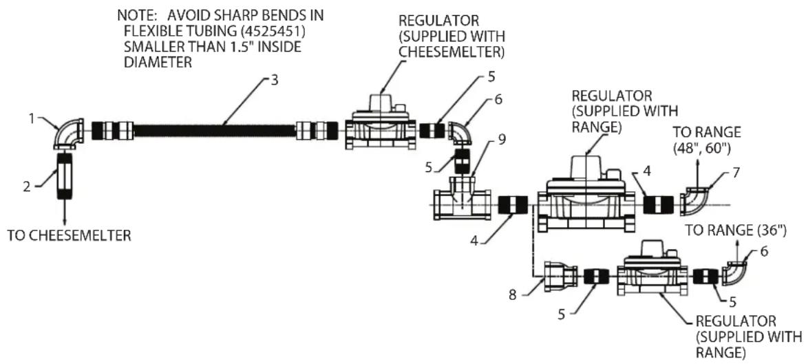
The gas supply of the range mounted cheesemelters (Models GIRCM36, GIRCM48 & GIRCM60) may be inter-connected with the supply of the range, so both units are supplied from a single gas connection. The supply gas piping should be a minimum of 1" (25mm) diameter to ensure enough gas capacity is available at the specified pressure to supply the total combined input rating of both appliances. The components comprising the optional inter-connect kit are shown below.
Optional Interconnect Gas Kit # 4523975
text_image
NOTE: AVOID SHARP BENDS IN FLEXIBLE TUBING (4525451) SMALLER THAN 1.5" INSIDE DIAMETER 1 2 TO CHEESEMELTER 3 5 6 9 4 5 REGULATOR (SUPPLIED WITH CHEESEMELTER) REGULATOR (SUPPLIED WITH RANGE) TO RANGE (48", 60") 7 4 TO RANGE (36") 6 8 5 REGULATOR (SUPPLIED WITH RANGE)| ITEM | PART # DESCRIPTION | QUANTITY | ||
| 36" | 48", 60" | |||
| 1 GO | 1474-9 Reducing | Elbow 3/4" NPT X 1/2" NPT 1 1 | ||
| 2 GO | 1896-2 Nipple | 1/2" NPT x 3-1/2" | 1 | |
| 3 | 4525451 | 72" Flexible S.S. Tub Assy | 1 | 1 |
| 4 | 076029-204 | Nipple 1" NPT x 2" | 1 | 2 |
| 5 | G01738-14 | Nipple 3/4" NPT x 2" | 4 | 2 |
| 6 GO | 1474-5 90° Elbow | 3/4" NPT | 2 | 1 |
| 7 | 076029-171 | 90° Elbow 1" NPT | 1 | |
| 8 | 2437100 | Reducing Adapter 1" NPT – 3/4" NPT | 1 | |
| 9 | 3012800 | Tee 1" NPT x 1" NPT x 3/4" NPT | 1 | 1 |
| 10 | 4523975 | Restaurant Universal Interconnect Kit | * | * |
Installation Of A Cheesemelter To A Range
NOTE: The back of the range must be easily accessible.
Model GIRCM36 - 36" Ranges
text_image
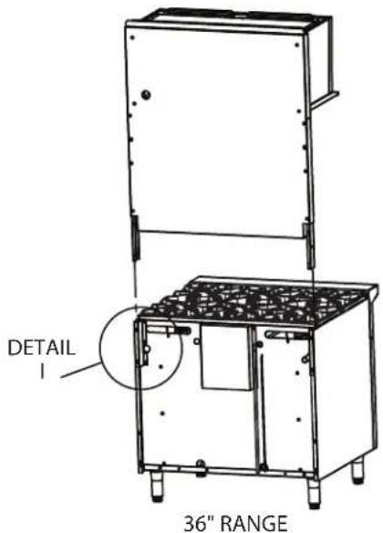
DETAIL 1 36" RANGEFigure 1 – With area detail defined for 36 inch range.
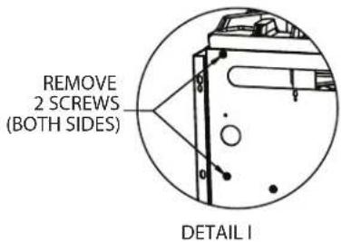
- Remove screws from back of oven (on both sides of range) as shown:
text_image
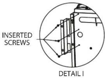
REMOVE 2 SCREWS (BOTH SIDES) DETAIL I- Install the left and right support brackets (part # 4523226 and 4523227) by re-inserting the 2 screws removed in step 1 and one additional screw (on both sides of the range).
text_image
INSERTED SCREWS DETAIL I-
Slide the cheesemelter down into the support brackets installed in step 2, see figure 1.
-
Once the cheesemelter is in place, fasten it to the unit on both sides of the range with the provided #14B x 5/8 hex washer head tapping screws.

text_image
PROVIDED #14B x 5/8 HEX WASHER HEAD TAPPING SCREWS DETAIL IModel GIRCM48 - 48" Ranges
text_image
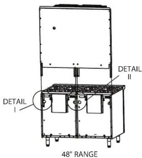
DETAIL I DETAIL II 48" RANGEFigure 2 – With area detail defined for 48 inch ranges.
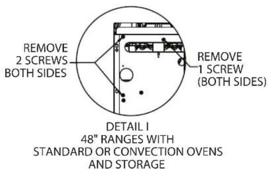
- Remove screws (a total of 10) from back of oven on both sides of the range (detail I) and center (detail II) as shown for each range model:
text_image
REMOVE 2 SCREWS BOTH SIDES REMOVE 1 SCREW (BOTH SIDES) DETAIL I 48" RANGES WITH STANDARD OR CONVECTION OVEN S AND STORAGE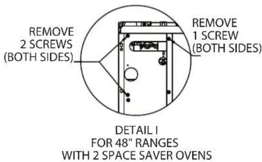
text_image
REMOVE 2 SCREWS (BOTH SIDES) REMOVE 1 SCREW (BOTH SIDES) DETAIL 1 FOR 48" RANGES WITH 2 SPACE SAVER OVEN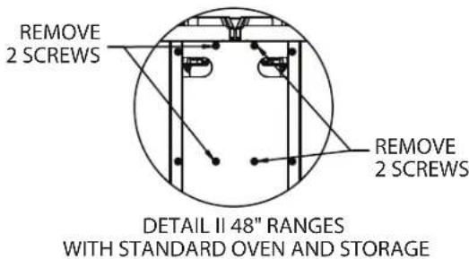
text_image
REMOVE 2 SCREWS REMOVE 2 SCREWS DETAIL II 48" RANGES WITH STANDARD OVEN AND STORAGE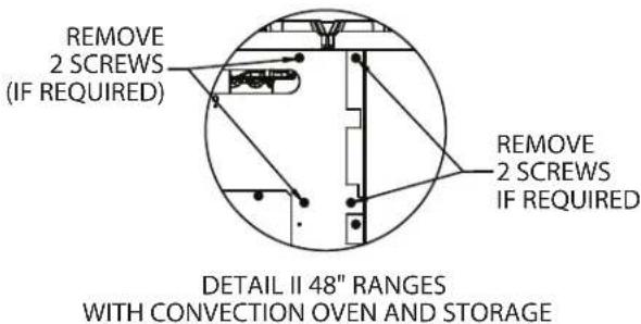
text_image
REMOVE 2 SCREWS (IF REQUIRED) REMOVE 2 SCREWS IF REQUIRED DETAIL II 48" RANGES WITH CONVECTION OVEN AND STORAGE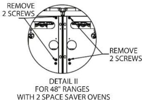
text_image
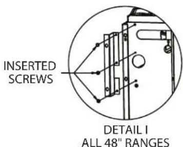
REMOVE 2 SCREWS DETAIL II FOR 48" RANGES WITH 2 SPACE SAVER OVEN- For all 48" ranges install the left and right support brackets (part # 4523226 and 4523227) by re-inserting the 2 screws removed in step 1 and one additional screw (on both sides of the range).
text_image
INSERTED SCREWS DETAIL I ALL 48" RANGES-
Slide the cheesemelter down into the support brackets installed in step 2, see figure 2. NOTE: On ranges with 2 space saver ovens, the center post must slide into the center channels built into the back of the unit.
-
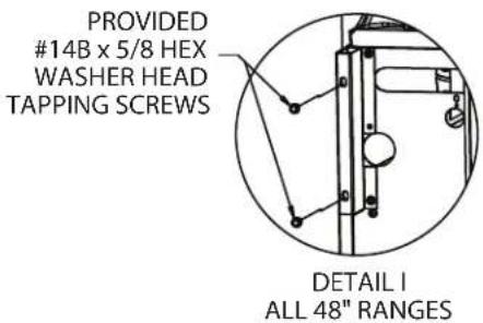
Once the cheesemelter is in place, fasten it to the unit on both sides of the range with the provided #14B x 5/8 hex washer head tapping screws.
text_image
PROVIDED #14B x 5/8 HEX WASHER HEAD TAPPING SCREWS DETAIL I ALL 48" RANGES- For center support, (detail II) re-insert screws removed in step 1 or provided sheet metal screws as shown in detail II and III, inserting screws for detail III through clearance in back panel.
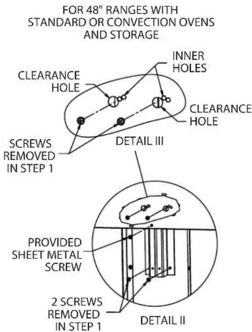
text_image
FOR 48" RANGES WITH STANDARD OR CONVECTION OVEN S AND STORAGE CLEARANCE HOLE INNER HOLES CLEARANCE HOLE DETAIL III CREWS REMOVED IN STEP 1 PROVIDED SHEET METAL SCREW 2 SCREWS REMOVED IN STEP 1 DETAIL IIFOR 48" RANGES WITH 2 SPACE SAVER OVENS
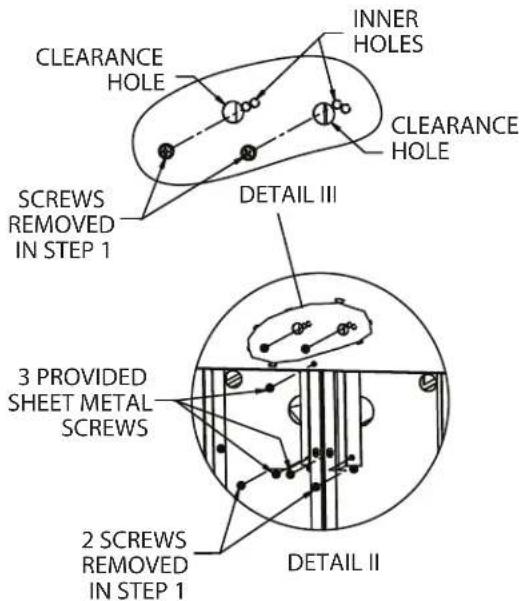
text_image
CLEARANCE HOLE INNER HOLES CLEARANCE HOLE SCREWS REMOVED IN STEP 1 DETAIL III 3 PROVIDED SHEET METAL SCREWS 2 SCREWS REMOVED IN STEP 1 DETAIL II- Re-insert screws removed in step 1 though clearance hole in back panel as shown:
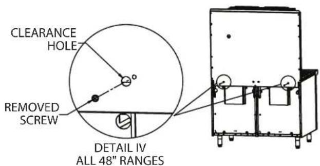
text_image
CLEARANCE HOLE REMOVED SCREW DETAIL IV ALL 48" RANGESModel GIRCM60 - 60" Ranges
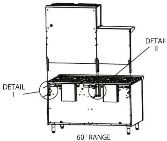
text_image
DETAIL I DETAIL II 60" RANGEFigure 3 – With area detail defined for 60 inch range.
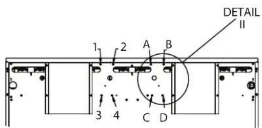
NOTE: Instructions are for mounting the cheesemelter on the right side, for mounting on the left side follow the same directions except use references 1, 2, 3, & 4 (to the left of detail II see below) in lieu of A, B, C, D for detail II in the following steps.
text_image
DETAIL II 1 2 A B 3 4 C D- Remove screws from back of oven on both sides of the range (detail I) and center (detail II) as shown:
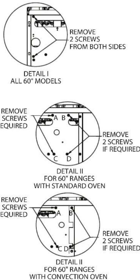
REMOVE
2 SCREWS
FROM BOTH SIDES
DETAIL I
ALL 60" MODELS
DETAIL II
FOR 60" RANGES
WITH STANDARD OVEN
DETAIL II
FOR 60" RANGES
WITH CONVECTION OVEN
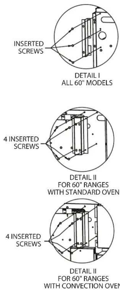
- Install the left and right support brackets (part # 4523226 and 4523227) using the 2 screws removed in step 1 (detail I) and one additional screw on both sides of the range, and center support bracket (part # 4523282) with the four screws removed in step 1 (detail II).
-
Slide the cheesemelter down into the support brackets installed in step 2, see figure 3.
-
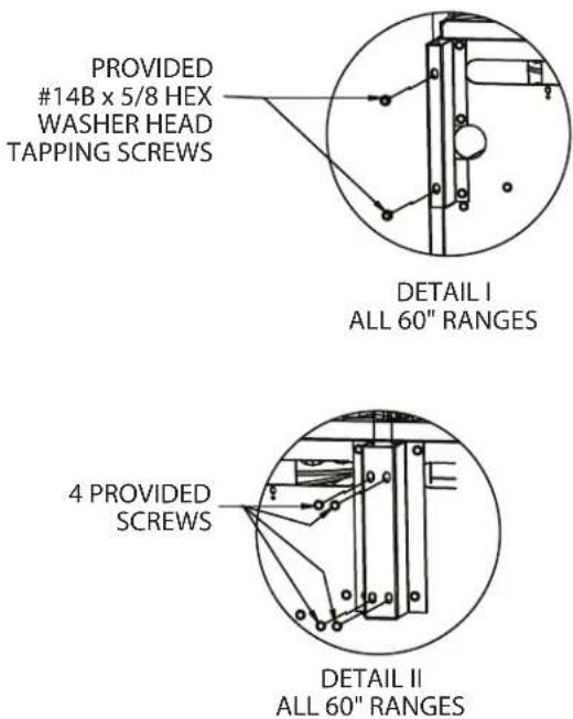
Once the cheesemelter is in place, fasten it to the unit on both sides of the range with the provided #14B x 5/8 hex washer head tapping screws (detail I) and the center to the support bracket using 4 of the provided screws (detail II).
Wall Or Counter Mounted Cheesemelters Model GIRCM36C
- Clearance from combustible construction must be six inches (6", 152mm) minimum at the rear and six inches (6", 152mm) minimum at both sides.
The appliance shall be located with respect to building construction and other equipment so as to permit access to the appliance. Such access and clearance may be necessary for service and cleaning.
-
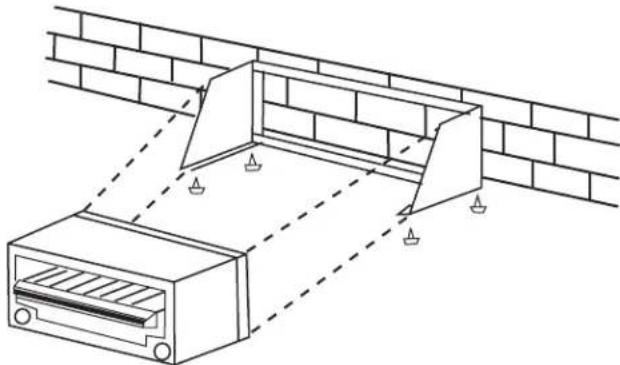
Counter models are furnished with 4" (102mm) legs. Level the unit with a carpenter's level and make minor adjustments with the threaded leg feet. Ensure that the counter top can support the weight of the appliance prior to installation and is comprised of non-combustible material.
-
Provisions for gas connections, top or rear, should be taken into consideration at time of installation.
- If the unit is to be mounted on a non-combustible wall contact the local authorities for local codes.
- Position, level, and mark location of the assembled wall mount kit.
- Drill wall (locating studs if necessary) to accept suitable fastening devices.
- Drill the angle iron bars of the wall mounting kit to match those drilled in the wall.
- Install wall mounting kit to wall.
- Install and secure cheesemelter with bolts supplied.
natural_image
Technical line drawing of a roof drainage system with a gridded wall and two rectangular components (no text or symbols)Ventilation and Air Supply
Proper ventilation is highly important for good operation. The ideal method of ventilation for a cheesemelter is the use of a properly designed canopy hood which should extend six inches (6", 152mm) beyond all sides of the appliance and six (6) feet six (6) inches (1981mm) from the floor.
A strong exhaust fan will create a vacuum in the room. For an exhaust system to work properly, replacement air must enter the room in which the vent is located. The amount of air which is exhausted must equal the amount entering, (make-up air).
All gas burners and pilots need sufficient air to operate and large objects should not be placed in front or on top of the cheesemelter which would obstruct the air flow through the front of the cheesemelter.
The following notes are intended to give general guidance. For detailed recommendations, refer to the applicable code(s) in the country of destination.
NOTE 1: The room containing the appliance is required to have a permanent air vent. The minimum effective area of the vent is related to the maximum rated heat input of the appliance and shall be 4.5cm^2 per kW (2.04 X 10⁻⁴ in² per BTU/H) in excess of 7 kW. (23,900 BTU/H).
NOTE 2: Air vents should be of such a size to compensate for the effects of any extract fan in the premises.
FOR YOUR SAFETY never place any type of object on top of the cheesemelter. The top of the cheesemelter will exceed 1000° F (538° C). It could cause severe burns and/or fire and also will obstruct ventilation.
Clearances
Clearance must be 6" (152mm) at the sides and rear from combustible material. A clearance of 0.0" to noncombustible construction at the sides & rear is acceptable, for the cheesemelter.
This appliance is for use on non-combustible floors/counters only.
Pilot Lighting Instructions
- The in-line service shut-off valve should be in the "ON" position.
- With a lighted taper you can now light the pilots which are located at the rear of the main burner.
Note: The pilots should be all operational and inspected by a licensed technical gas technician prior to operating the unit.
- The Pilot flame should be approximately 7/8" long for proper ignition of the burners.
NOTE: No more than 7/8" pilot flame length should be required. Too high a setting will cause the flame to lift off or will create excessive carbon deposits. Do not adjust the pilot flame lower than 7/8" long because this can cause delayed ignition at the burner. The delayed ignition could cause the burner tiles to crack; in that case the burner would have to be replaced. If the pilot flame does not seem to be within specifications, have an authorized technician inspect the unit.
Main Burner Operation
Turn main burner knob to the "MAX" position and immediately check ignition.
CAUTION Should ignition fail after five seconds, turn valve off and wait five minutes before trying again. Pilot gas is not interrupted automatically. It is the responsibility of the operator to check the ignition of burners immediately after the burner valve has been turned on.
When ignition has been accomplished, a blue flame will cover the surface of the ceramics for 10-15 seconds. The haze will disappear and the burner rod will glow red. After the burners have operated for several minutes turn the valve to "MIN." The burner rods will no longer glow red and the flame travels back and forth on the face of the burner ceramics.
Burn off Period
Many parts used in the manufacturing of commercial equipment have a thin, protective coating of machine oil. This oil should be burned off before the equipment is used for food preparation.
After all start-up and safety checks have been completed, turn burner valve to the "MAX" position. Smoke (a bluish haze) will be produced. This process can take several hours and can be completed over a few days.
Energy Conservation
Do not waste energy by leaving controls at high temperature settings during idle periods. Lower settings will keep cheesemelter warm and ready for next use period. Reset burner valve knob as required for heavy load periods.
Shut Down Instructions
Turn main burner valve knobs to the "OFF" position. If the unit is to be shut down for an extended period of time, close the manual in-line service valve (manual in-line service valve is not factory supplied).
FOR YOUR SAFETY never place any type of object on top of the cheesemelter. The top of the cheesemelter will exceed 1000° F. It could cause severe burns and/or fire and also will obstruct ventilation.
Main Burner Adjustments
All cheesemelters are provided with fixed burner orifices to provide 15,000 BTU/HR at the "MAX" setting on Natural Gas supplied at 6.0" WC (15 mbar) pressure or propane gas supplied at 10.0" WC (25 mbar) pressure.
Proper adjustment is attained at the point where the burner rods no longer glow and the flame travels back and forth on the face of the ceramics.
This adjustment has been factory pre-set, however, with changing pressures this adjustment and pilot adjustment may need to be re-done after installation.
This is not considered a manufacturing defect and is not warrantable.
NOTE : Burner adjustments should only be done by an authorized service technician.
WARNING if gas odors are detected, the gas supply must be turned "OFF" at the main shut-off valve and the local gas company or authorized service agency contacted for service.
A program of proper cleaning techniques will aid in continued trouble free operation of this or any quality equipment.
Daily
The rack and rack guides should be wiped daily while still warm, using a heavy cloth or other grease absorbing material to remove grease and burnt food before they burn into the grid. Remove burnt materials, such as carbonized grease or food, with a stiff wire brush. DO NOT USE ANY TYPE OF STEEL WOOL. Small particles may be left on the rack surface and get into food products. The rack should be washed thoroughly using a wire brush and a hot, mild detergent or soap solution. Rinse with clear, warm water.
Monthly
Lubricate valves and bearings as required. Due to the usual location of the cheesemelter that is mounted above a range with open tops, the heat from the open top will cause the lubrication grease inside the valves to dry out. When you notice that the valve is becoming harder to turn it is then time to have them greased. We suggest an Authorized Service Agent who is familiar with the appliance and working with natural and propane gas, to perform this type of work.
Exterior Cleaning
Establish a regular schedule. Any spills should be wiped off immediately.
-
Wipe exposed, cleanable surface when cool with a mild detergent and hot water. Stubborn residue spots may be removed with a light weight non-metallic scouring pad. Dry thoroughly with a clean cloth.
-
Stainless steel should be cleaned using a mild detergent, a soft cloth and hot water. If it is necessary to use a non-metallic scouring pad, always rub in the direction of the grain in the metal to prevent scratching. Use a water based stainless steel cleaner (such as Drackett Twinkle), if you want a high shine.
Garland
INSTRUCTIONS D'INSTALLATION ET D'UTILISATION
SALAMANDRES À FROMAGE À INFRAROUGE GARLAND SÉRIE G



natural_image
Exterior view of a stainless steel laboratory appliance with open lid and side outlets (no visible text or symbols)POUR VOTRE SÉCURITÉ : NE PAS STOCKER NI UTILISER D'ESSENCE OU D'AUTRES VAPEURS OU LIQUIDES INFLAMMABLES À PROXIMITÉ DE CET APPAREIL OU DE TOUT AUTRE APPAREIL.
AVERTISSEMENT : UNE INSTALLATION, DES RÉGLAGES, DES MODIFICATIONS, DES RÉPARATIONS OU UN ENTRETIEN MAL FAITS PEUVENT CAUSER DES DOMMAGES MATÉRIELS, DES BLESSURES OU LA MORT. LIRE SOIGNEUSEMENT LES INSTRUCTIONS D'INSTALLATION, D'UTILISATION ET D'ENTRETIEN AVANT D'INSTALLER OU DE RÉPARER L'ÉQUIPEMENT.
NE PAS OBSTRUER LA CIRCULATION D'AIR DE COMBUSTION ET DE VENTILATION DE CET APPAREIL.
LIRE TOUTES LES SECTIONS DU PRÉSENT MANUEL ET LE CONSERVER POUR S'Y REPORTER ULTÉRIEUREMENT.
CE PRODUIT A ÉTÉ HOMOLOGUÊ EN TANT QU'ÉQUIPEMENT PROFESSIONNEL DE CUISSON ET DOIT ÊTRE INSTALLÉ PAR DU PERSONNEL PROFESSION- NEL TEL QUE SPÉCIFIÉ.
DANS L'ÉTAT DU MASSACHUSETTS, CE PRODUIT DOIT ÊTRE INSTALLÉ PAR UN PLOMBIER OU UN MONTEUR D'INSTALLATION AU GAZ CERTIFIÉ.
185 East South Street
Freeland, Pennsylvania 18224
1177 Kamato Road, Mississauga, Ontario L4W 1X4
CANADA
INFORMATIONS GÉNÉRALES....2 2
Performance Et Construction Des Salamandres À Fromage .....22
INSTALLATION 22
Exigences Des Codes Nationaux....22
natural_image
Technical line drawing of a roof drainage system with a gridded wall and two rectangular components (no text or symbols)Ventilation Et Alimentation En Air
natural_image
Exterior view of a stainless steel laboratory oven with grilles and control knobs (no visible text or symbols)PARA SU SEGURIDAD: NO ALMACENE O UTILICE GASOLINA U OTROSVAPORES O LÍQUIDOS INFLAMABLES EN LASCERCANÍAS DE ESTE O CUALQUIER OTRO ARTEFACTO.
185 East South Street
Freeland, Pennsylvania 18224
1177 Kamato Road, Mississauga, Ontario L4W 1X4
CANADÁ
natural_image
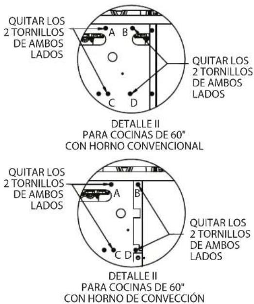
Pure mechanical diagram showing a bracket with mounting holes and a circular component, no text or symbols present.QUITAR LOS
2 TORNILLOS
DE AMBOS LADOS
DETALLE I
TODOS LOS MODELOS DE 60"