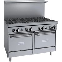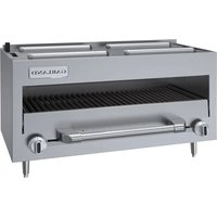
GFIR36CM - Grill GARLAND - Free user manual and instructions
Find the device manual for free GFIR36CM GARLAND in PDF.


User questions about GFIR36CM GARLAND
0 question about this device. Answer the ones you know or ask your own.
Ask a new question about this device
Download the instructions for your Grill in PDF format for free! Find your manual GFIR36CM - GARLAND and take your electronic device back in hand. On this page are published all the documents necessary for the use of your device. GFIR36CM by GARLAND.
USER MANUAL GFIR36CM GARLAND
INSTALLATION AND OPERATION MANUAL
GARLAND GF SENTRY SERIES INFRA-RED SALAMANDER BROILERS





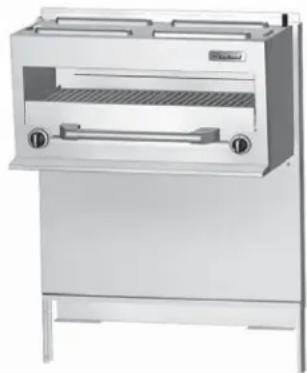
natural_image
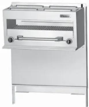
Exterior view of a stainless steel grater appliance (no visible text or symbols)Français Page 19
DO NOT STORE OR USE GASOLINE OR OTHER FLAMMABLE VAPORS OR LIQUIDS IN THE VICINITY OF THIS OR ANY OTHER APPLIANCE
WARNING:
IMPROPER INSTALLATION, ADJUSTMENT, ALTERATION, SERVICE OR MAINTENANCE CAN CAUSE PROPERTY DAMAGE, INJURY, OR DEATH. READ THE INSTALLATION, OPERATING AND MAINTENANCE INSTRUCTIONS THOROUGHLY BEFORE INSTALLING OR SERVICING THIS EQUIPMENT
DO NOT OBSTRUCT THE FLOW OF COMBUSTION AND VENTILATION AIR TO THIS APPLIANCE
PLEASE READ ALL SECTIONS OF THIS MANUAL AND RETAIN FOR FUTURE REFERENCE.
THIS PRODUCT HAS BEEN CERTIFIED AS COMMERCIAL COOKING EQUIPMENT AND MUST BE INSTALLED BY PROFESSIONAL PERSONNEL AS SPECIFIED.
IN THE COMMONWEALTH OF MASSACHUSETTS THIS PRODUCT MUST BE INSTALLED BY A LICENSED PLUMBER OR GAS FITTER.
For Your Safety:
Post in a prominent location, instructions to be followed in the event the user smells gas. This information shall be obtained by consulting your local gas supplier.
Users are cautioned that maintenance and repairs must be performed by a Garland authorized service agent using genuine Garland replacement parts. Garland will have no obligation with respect to any product that has been improperly installed, adjusted, operated or not maintained in accordance with national and local codes or installation instructions provided with the product, or any product that has its serial number defaced, obliterated or removed, or which has been modified or repaired using unauthorized parts or by unauthorized service agents. For a list of authorized service agents, please refer to the Garland web site at http://www.garland-group.com. The information contained herein, (including design and parts specifications), may be superseded and is subject to change without notice.
GARLAND COMMERCIAL RANGES, LTD.
1177 Kamato Road, Mississauga, Ontario L4W 1X4
CANADA
Phone: 905-624-0260
Fax: 905-624-5669
General Inquires 1-905-624-0260
USA Sales 1-800-424-2411
Canadian Sales 1-888-442-7526
Canada or USA Parts/Service 1-844-724-2273
WARNING:
This product contains chemicals known to the State of California to cause cancer and/or birth defects or other reproductive harm. Installation and servicing of this product could expose you to airborne particles of glass wool/ceramic fibers. Inhalation of airborne particles of glass wool/ceramic fibers is known to the State of California to cause cancer. Operation of this product could expose you to carbon monoxide if not adjusted properly. Inhalation of carbon monoxide is known to the State of California to cause birth defects or other reproductive harm.
Keep appliance area free and clear of combustibles.
TABLE OF CONTENTS
IMPORTANT INFORMATION.....2
INTRODUCTION....4
Product Application 4
Uncrating 4
Rating Plate 4
Safety Information 4
DIMENSIONS AND SPECIFICATIONS ..... 5
CE Gas Categories 6
Gas Pressure And Ratings....6
CE & General International Countries ..... 6
Setting Pressure For "MIN" Tap Position.... 6
North America 6
Australian Market 6
Gas Inlet Size 6
GENERAL INFORMATION ....7
Siting....7
Statutory Regulations....7
Australia Specific Regulations 7
INSTALLATION....7
National Code Requirements....7
Gas Connections....8
Optional Inter-Connect Kit 9
Installation Of A Salamander To A Range ..... 11
Model GFIR36 – 36" Ranges ..... 11
Model GFIR48 – 48" Ranges.... 12
Model GFIR60 - 60" Ranges....14
Wall Or Counter Mounted Salamanders ..... 15
Model GFIR36C.... 15
Ventilation and Air Supply 16
Clearances 16
Burner Adjustments....16
OPERATION....17
Safety concerns 17
Lighting The Salamander....17
Operating Suggestions....17
Operating Controls....17
MAINTENANCE AND CLEANING ..... 18
Daily....18
Monthly....18
Exterior Cleaning ....18
Units included in this manual are:
Salamander Models: GFIR36C, GFIR36, GFIR48, GFIR60
All units are shipped completely assembled with the pressure regulator packed inside the unit drip tray if included. Units are inspected at the factory prior to shipment.
The appliance should be given regular care and maintenance. Periodic inspections by your dealer or a qualified service agency are recommended.
This product has been certified as commercial cooking equipment and must be installed by professional personnel as specified.
Product Application
The Garland infra-red salamander offers broiling for a wide variety of products such as steak, lobster, fish, onion soup, casseroles, garlic bread and hamburgers. The over-fi re infrared design provides for quick preheat and efficient, uniform production. The tilting rack feature allows for an easy view broiling.
Uncrating
Check the crate for possible damage during transit. Carefully remove the unit from the crate and again check for damage. If damage has occurred, report it to the carrier immediately.
Shipping wire, or ties for retaining the packaging material must be removed from the units, as well as any protective material covering stainless steel.
DO NOT remove any permanently affi xed label warnings or the rating plate from the appliance, as this may invalidate the manufacturer's warranty.
The type of gas and supply pressure that the equipment was set-up for at the factory are indicated on the rating plate and packaging. The type of gas and pressure specified must be supplied to the unit.
Rating Plate
The rating plate is affi xed to the Salamander front panel and is located underneath the removable drip tray.
When corresponding with the factory or your local authorized factory service center regarding service problems or replacement parts, be sure to refer to the particular unit by the correct model number (including the prefix and suffix letters and numbers) and the warranty serial number. The rating plate contains this information.
The rating plate also contains the gas type and supply pressure, as well as listing the input rating of all burners.
In the event you have any questions concerning the installation, use, care or service of the product, write or call our Product Service Department.
Safety Information
Warning: Accessible parts may become hot during use. Young children should be kept away.
This product is intended for professional use by qualified personnel. The appliance is not intended for use by persons (including children) with reduced physical, sensory or mental capabilities, or lack of experience and knowledge, unless they have been given supervision or instruction concerning use of the appliance by a person responsible for their safety.
| Model | Description Width | Use With GF Series Model | Shipping Information | Entry Clearances | |||
| Cu Ft lbs/Kg Crated Uncrated | |||||||
| GFIR36C | Counter/Wall Mount | 34"(864mm) | N/A 21 | 70/77 | 31"(787mm) | 21"(533mm) | |
| GFIR36 | Range Mount | 35-1/2"(900mm) | GF/GFE36 | 38.2 | 200/91 | 31"(787mm) | 21"(533mm) |
| GFIR48 | Center Mounted Broiler With Extended Flue On Both Sides | 47-1/4"(1200mm) | GF/GFE48 | 60.6 | 230/105 | 31"(787mm) | 21"(533mm) |
| *GFIR60 | Broiler With 24"(610 mm)Flue Riser And Shelf | 59-1/16"(1500mm) | GF/GFE60 | 60.6 | 260/118 | 31"(787mm) | 21"(533mm) |
* Note: for range models, salamanders are standard on right but available on the left as an option. For raised griddle/broiler models, salamanders are only available on left side of the range.
| Model Combustible Clearances | ||||
| Counter | For use in non-combustible locations only | |||
| Range Mount | Sides | 6"(152mm) | Back | 6"(152mm) |
Garland/U.S. Range products are not approved or authorized for home or residential use, but are intended for commercial applications only. Garland / U.S. Range will not provide service, warranty, maintenance or support of any kind other than in commercial applications.
Please specify gas type when ordering.
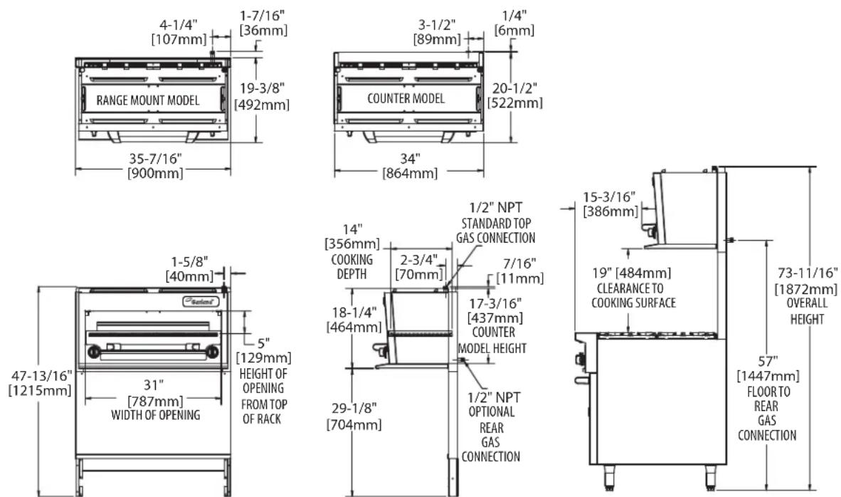
DIMENSIONS AND SPECIFICATIONS continued
CE Gas Categories
| Country | Gas Category | Gas Type | Pressure (mbar) |
| GB, IE, ES, PT, GR | I_2H | G20 20 | |
| GB, IE, ES, PT, BE, FR | I_3P | G31 37 | |
| FR, NL, DE, ES | I_3P | G31 50 |
Gas Inlet Size
| Connection(North America & Australia) | Connection CE Models(ISO7-1) |
| 3/4” NPT Top Gas Connection | 3/4” (19.1mm) BSPT |
Gas Pressure And Ratings
CE & General International Countries
Pressure Setting / Injector Size
| MODELS | 2nd Family, Group H G20 @ 20 mbar inlet | 3rd Family, Group P G31 @ 37/50 mbar inlet | ||||
| Setting Pressure* | Injector Size | Setting Pressure* | Injector Size | |||
| mbar DM | MS mm mbar | DMS mm | ||||
| GFIR 20 1.6mm 1.6 | 37 1.1mm 1.1 | |||||
| 50 61 0.99 | ||||||
* No appliance pressure regulator used, pressure measured at the test nipple on main manifold with all burners lit.
Heat Input (Gross)
| MODELS | 2nd Family, Group H (G20 @ 20 mbar) NAT | 3rd Family, Group P (G31 @ 37/50 mbar) PROPANE | # Of Burners |
| kW Per Burner kW Per Burner | |||
| GFIR 4.2 4.2 | 2 | ||
Setting Pressure For "MIN" Tap Position
| MODELS | 2ND Family, Group H (G20 @ 20 mbar) NAT. GAS | 3RD Family, Group 3P (G31 @ 37/50 mbar) PROPANE | ||
| mbar | “W.C. | mbar | “W.C. | |
| GFIR | 10.5 | 4.2 | 23 | 9.4 |
North America
| Operating Manifold Pressure | |
| Natural 4.0” wc | Propane 10.0” wc |
| Total Input | |
| BTU/H | BTU/H |
| 28,000 | 26,000 |
Australian Market
| Operating Manifold Pressure | |||
| Natural 1 kPa (4.0” wc) | LPG 2.49 kPa (10.0” wc) | ||
| Total Input | |||
| MJ/H | Injector Dia. | MJ/H | Injector Dia. |
| 21.0 | 2.4 mm | 21.0 | 1.4mm |
Gas input ratings shown here are for installations up to 2,000 ft. (610m) above seal level. Specify altitudes over 2,000 ft.
The range-mounted, gas Infra-Red Salamander Broiler is designed for a perfect match and fit to the Garland GF series Range.
Garland products are not approved or authorized for home or residential use, but are intended for commercial applications only. Garland will not provide service, warranty, maintenance or support of any kind other than in commercial applications.
Siting
The counter top unit should be installed on a fi rm, smooth and level base capable of adequately supporting the weight of the appliance and any ancillary equipment. (Refer to Dimensions and Specifications section for weight specifications). Any openings in the wall behind or beside the appliance must be sealed. Once in position check that the unit is level, both front to back and side to side. Adjust if necessary using the leveling feet on the four corners of the fitted legs.
Statutory Regulations
The installation of this appliance must be carried out by a competent person and in accordance with the relevant regulations, standards, codes of practice and the related publications of the Country of destination.
Australia Specific Regulations
This appliance must be installed in accordance with the manufacturers instructions, local gas fi tting regulations and requirements of AS 5601 / AG 601 installation code. All burner adjustments and settings should be made by a qualifi ed gas technician.
INSTALLATION
This product has been certified as commercial cooking equipment and must be installed by professional personnel as specified. THIS APPLIANCE IS NOT RECOMMENDED FOR RESIDENTIAL INSTALLATION.
We suggest installation, maintenance and repairs be preformed by your local Garland/US Range authorized service agency.
National Code Requirements
In European countries, installation must be carried out by a competent person and in accordance with the relevant regulations, codes of practice and the related publications of the country of destination.
The importance of the proper installation of Commercial Gas Cooking Equipment cannot be over stressed. Proper performance of the equipment is dependent, in great part, on the compliance of the installation with the manufacturer's specifications. Installation must conform to local codes or, in the absence of local codes, with the National Fuel Gas Code, NFPA54 / ANSI Z223.1 or latest edition, Natural Gas Installation Code, CAN/GCA-B149.1 or the Propane Installation Code, CAN/CGA-B149.2 or latest editions, as applicable.
Gas Connections
text_image
Danger Turn Off Gas Supplies When Installing or Servicing Unit.All fixed (non mobile) appliances MUST be fitted with a manual gas cock upstream of the appliance to provide a means of isolation for servicing or cleaning purposes. A union or similar means of disconnection must be provided between the gas cock and the appliance.
A manually operable valve must be fitted to the gas supply to the kitchen to enable it to be isolated in an emergency. Whenever practical, this shall be located either outside the kitchen of near an exit in a readily accessible position.
Where it is not practical to do this, an automatic isolation valve system shall be fitted which can be operated from a readily accessible position or near to the exit.
At locations where the manual isolation valve is fitted or the automatic system can be reset, a notice MUST be fitted stating:
"ALL DOWNSTREAM BURNER AND PILOT VALVES MUST BE TURNED OFF PRIOR TO ATTEMPTING TO RESTORE THE SUPPLY. AFTER EXTENDED SHUT OFF, PURGE BEFORE RESTORING GAS."
Before assembly and connection, check gas supply.
A. The type of gas for which the unit is equipped is stamped on the rating plate located on the lower front panel simply remove the drip tray for easy access. Connect a unit stamped "NAT" only to natural gas; connect those stamped "PRO" only to propane gas.
B. If it is additional equipment or a replacement have a qualified gas technician check the gas pressure to make certain that existing gas facilities (meter piping, etc.) will supply gas to the unit with no more than 1/2" water column pressure drop.
NOTE: When checking pressure, be sure that all other equipment on the same gas line is on. If Garland supplied the regulator with the unit, it has been preset to deliver the gas pressure shown on the rating plate. If sourcing the regulator adjust pressure as shown on the rating plate.
C. The appliance and its individual shut off (supplied by others) must be disconnected from the gas supply piping system during any pressure testing of that system at pressures in excess of 1/2 psi (3.45 kPa).
D. The appliance must be isolated from the gas supply piping system by closing its individual manual shut off valve (supplied by others) during any pressure testing of the gas supply piping system at test pressures equal to or less than 1/2 psi (3.45 kPa).
E. The gas supply connection is made either at the top left rear or lower rear right corner, depending on how the unit was ordered. A readily accessible approved type of hand valve should be installed on each supply line. Test for leaks – DO NOT USE ANY OPEN FLAME.
F. A pressure tap plug is supplied with the units and it is installed on the manifold. The drip tray must be removed to use the pressure tap. The gas pressure must be checked when the unit is installed, to insure that the unit gas pressure is the same as specified on the rating plate. If necessary, pressure adjustments must be made at the supplied pressure regulator.
NOTE: the pressure regulator is located at the top left rear or bottom right rear of the salamander. For European Countries, the gas supply pressure is to be regulated according to the information on the rating plate - regulator not included with the appliance.
G. If it is a completely new installation, have a qualified gas technician check meter size and piping to ensure that the unit is supplied with a sufficient amount of gas at the specified pressure for unit operation.
H. Make certain that the new piping, joints and connections have been made in a clean manner and have been purged, so that the piping compound, chips, etc, will not clog pilots, valves and/or controls. Use pipe joint sealant that is resistant to liquefi ed petroleum gas.
WARNING Check gas connections for leaks. Use a soap solution or similar means. DO NOT USE AN OPEN FLAME!
INSTALLATION Continued
Optional Inter-Connect Kit
(Models GFIR36, GFIR48 & GFIR60)
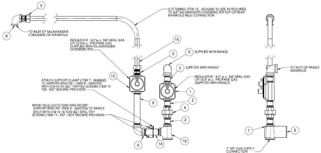
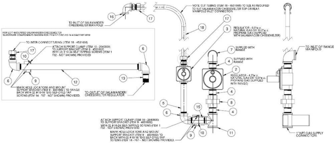
The gas supply of the range mounted salamanders may be inter-connected with the supply of the range, so both units are supplied from a single gas connection. The supply gas piping should be a minimum of 1" (25mm) diameter to ensure enough gas capacity is available at the specified pressure to supply the total combined input rating of both appliances. The components comprising the optional inter-connect kit are shown below.
Optional Interconnect Gas Kit #4531606 - Version 1, Connecting to a 36in Range
text_image
5 8 TO INLET OF SALAMANDER/ CHEESEMELTER MANIFOLD REGULATOR - 6.0"w.c. NATURAL GAS OR 10.0"w.c. PROPANE GAS (SUPPLIED WITH SALAMANDER/ CHEESEMELTER) 13 ATTACH SUPPORT CLAMP (ITEM 7 - 2640800) TO SUPPORT BRACKET (ITEM 6 - 2640700) WITH (2)#10-24 SELF-TAPPING SCREWS (ITEM 12 F32 - NOT SHOWN) PROVIDED. MARK HOLE LOCATIONS AND MOUNT SUPPORT BRACKET (ITEM 6 - 2640700) TO RANGE BACK WITH (2)#10-16 TEKS SELF-DRILL/TAP SCREWS (ITEM 11 - F67 - NOT SHOWN) PROVIDED. 14 9 15 5 3 SUPPLIED WITH RANGE 2 SUPPLIED WITH RANGE REGULATOR - 4.5" w.c. NATURAL GAS OR 10.0" w.c. PROPANE GAS (SUPPLIED WITH RANGE) 1 2 4 2 10 3 7 6 1" NPT GAS SUPPLY CONNECTION CUT TUBING (ITEM 15 - 4531608) TO SIZE AS REQUIRED TO SUIT SALAMANDER/CHEESEMELTER TOP OR REAR MANIFOLD INLET CONNECTION TO INLET OF RANGE MANIFOLD| ITEM | DESCRIPTION QUANTITY 36" | |
| 1 | 4.5" W.C 3/4"NPT, Regulator Natural Gas, supplied with Range 1 | |
| 3/4" ISO 7-1, Regulator Natural Gas, supplied with Range 1 | ||
| 10" W.C 3/4"NPT, Regulator Propane Gas, supplied with Range 1 | ||
| 3/4" ISO 7-1, Regulator Propane Gas, supplied with Range 1 | ||
| 2 Nipple, 3/4" NPT x 1/2" (one supplied with range) 3 | ||
| 3 Elbow, 90deg, 3/4" NPT (one supplied with range) | 2 | |
| 4 Union, 3/4" NPT | 2 | |
| 5 3/4"CC x 3/4" NPT Straight Fitting | 2 | |
| 6 Bracket, Pipe Support | 1 | |
| 7 Clamp, Pipe Support Bracket | 1 | |
| 8 Reducing Elbow, 90deg, 3/4" NPT x 1/2" NPT | 1 | |
| 9 Nipple, 3/4" NPT x 6.5" | 1 | |
| 10 | Reducing Tee, 3/4" NPT x 3/4" NPT x 1" | 1 |
| 11 | Screw, #10-16 x 1/2" Hex, Washer Head, Teks Self-Drill/Tap (not shown) | 2 |
| 12 | Screw, #10-24 x 1/2" Pan Head, Self-Tap, Type F (not shown) | 2 |
| 13 | 6" W.C 3/4" NPT, Regulator Natural Gas, supplied with Salamander/Cheesemelter | 1 |
| 10" W.C 3/4" NPT, Regulator Propane Gas, supplied with Salamander/Cheesemelter | 1 | |
| 14 | Nipple, 3/4" NPT x 3.5" | 1 |
| 15 | Tubing 3/4" | 1 |
Optional Interconnect Gas Kit #4531606 - Version 2, Connecting to a 48in or 60in Range
text_image
TO INLET OF SALAMANDER/ CHEESEMELTER MANIFOLD FOR LEFT-MOUNTED SALAMANDER/CHEESEMELTER SUBSTITUTE COMPONENTS SHOWN FOR ITEM 17 CIRCLED IN ADJACENT VIEW TO INTER CONNECT TURING (ITEM 18 - 4531608) ATTACH SUPPORT CLAMP (ITEM 10 - 2640800) TO SUPPORT BRACKET (ITEM 9 - 4531602) WITH (2) #10-24 SELF-TAPPING SCREWS (ITEM 1 F32 - NOT SHOWN) PROVIDED MARK HOLE LOCATIONS AND MOUNT SUPPORT BRACKET (ITEM 9 - 4531602) TO RANGE BACK WITH (2) #10-16 TEAS SELF-DRILL TAP SCREWS (ITEM 14 - F37 NOT SHOWN) PROVIDED. TO OUTLET OF SALAMANDER/ CHEESEMELTER REGULATOR NOTE: CUT TUBING (ITEM 18 - 4531608) TO SIZE AS REQUIRED TO SUIT SALAMANDER/CHEESEMELTER TOP OR REAR MANIFOLD INLET CONNECTION REGULATOR - 6.0w.c. NATURAL GAS OF 10.0w.c. PROpane GAS (SUPPLIED WITH SALAMANDER CHEESEMELTER) SUPPLIED WITH RANGE SUPPLIED WITH RANGE REGULATOR - 4.5w.c. NATURAL GAS OF 10.0w.c. PROpane GAS (SUPPLIED WITH RANGE) TO INLET OF RANGE MANIFOLD ATTACH SUPPORT CLAMP (ITEM 10 - 2640800) TO SUPPORT BRACKET (ITEM 9 - 4531602) WITH (2) #10-24 SELF-TAPPING SCREWS (ITEM 1 F32 - NOT SHOWN) PROVIDED MARK HOLE LOCATIONS AND MOUNT SUPPORT BRACKET (ITEM 9 - 4531602) TO BACK WITH (2) #10-16 TEAS SELF-DRILL TAP SCREWS (ITEM 14 - F37 - NOT SHOWN) PROVIDED. 1' NPT GAS SUPPLY CONNECTION| ITEM DESCRIPTION | QUANTITY48" / 60" | |
| 1 Screw, #10-24 x 1/2" Pan Head, Self-Tap, Type F (not shown) 4 | ||
| 2 | 4.5" W.C 1"NPT, Regulator Natural Gas, supplied with Range 1 | |
| 1" ISO 7-1, Regulator Natural Gas, supplied with Range 1 | ||
| 10" W.C 1"NPT, Regulator Propane Gas, supplied with Range 1 | ||
| 1" ISO 7-1, Regulator Propane Gas, supplied with Range 1 | ||
| 3 | 6" W.C 3/4" NPT, Regulator Natural Gas, supplied with Salamander/Cheesemelter 1 | |
| 10" W.C 3/4" NPT, Regulator Propane Gas, supplied with Salamander/Cheesemelter 1 | ||
| 4 Nipple, 1" NPT x 2" (one supplied with range) 3 | ||
| 5 Nipple, 3/4" NPT x 6.5" | 1 | |
| 6 Elbow, 90deg, 3/4" NPT | 3 | |
| 7 Elbow, 90deg, 1" NPT (supplied with range) | 1 | |
| 8 Union, 1" NPT | 1 | |
| 9 Bracket, Pipe Support 48/60 | 2 | |
| 10 | Clamp, Pipe Support Bracket | 2 |
| 11 | Reducing Tee, 1" NPT x 1" NPT x 3/4" | 1 |
| 12 | Nipple, 3/4" NPT x 22.75" | 1 |
| 13 | Nipple, 3/4" NPT x 2" | 1 |
| 14 | Screw, #10-16 x 1/2" Hex, Washer Head, Teks Self-Drill/Tap (not shown) | 4 |
| 15 | Nipple, 3/4" NPT x 3.5" | 1 |
| 16 | Reducing Elbow, 90deg, 3/4" NPT x 1/2" NPT | 1 |
| 17 | 3/4"CC x 3/4" NPT Straight Fitting | 2 |
| 18 | Tubing 3/4" | 1 |
SAFETY FIRST
USE PROPER LIFTING TECHNIQUES
Installation Of A Salamander To A Range
NOTE: The back of the range must be easily accessible.
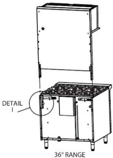
Model GFIR36 - 36" Ranges
text_image
DETAIL 36" RANGEFigure 1 – With area detail defined for 36 inch range.
- Remove screws from back of oven (on both sides of range) as shown:
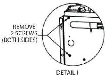
text_image
REMOVE 2 SCREWS (BOTH SIDES) DETAIL I- Install the left and right support brackets (part # 4523226 and 4523227) by re-inserting the 2 screws removed in step 1 and one additional screw (on both sides of the range).
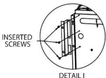
text_image
INSERTED SCREWS DETAIL I-
Slide the salamander down into the support brackets installed in step 2, see figure 1.
-
Once the salamander is in place, fasten it to the unit on both sides of the range with the provided #14B x 5/8 hex washer head tapping screws.
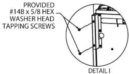
text_image
PROVIDED #14B x 5/8 HEX WASHER HEAD TAPPING SCREWS DETAIL IModel GFIR48 - 48" Ranges
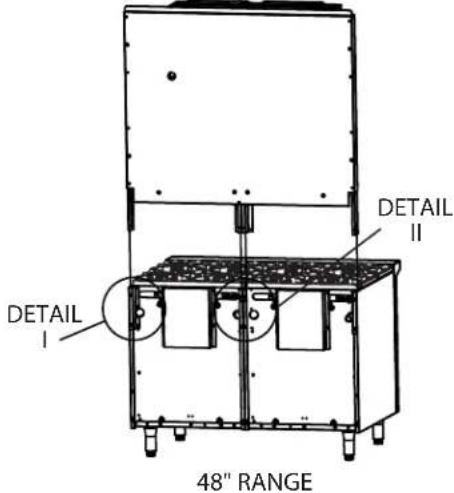
text_image
DETAIL I DETAIL II 48" RANGEFigure 2 – With area detail defined for 48 inch ranges.
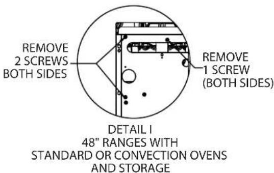
- Remove screws (a total of 10) from back of oven on both sides of the range (detail I) and center (detail II) as shown for each range model:
text_image
REMOVE 2 SCREWS BOTH SIDES REMOVE 1 SCREW (BOTH SIDES) DETAIL I 48" RANGES WITH STANDARD OR CONVECTION OVEN S AND STORAGE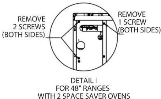
text_image
REMOVE 2 SCREWS (BOTH SIDES) REMOVE 1 SCREW (BOTH SIDES) DETAIL | FOR 48" RANGES WITH 2 SPACE SAVER OVEN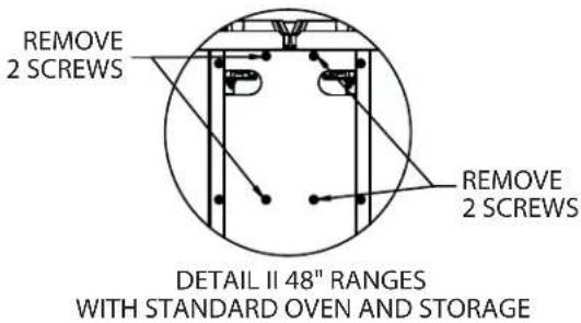
text_image
REMOVE 2 SCREWS REMOVE 2 SCREWS DETAIL II 48" RANGES WITH STANDARD OVEN AND STORAGE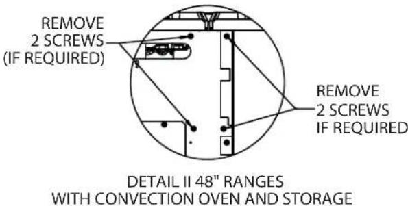
text_image
REMOVE 2 SCREWS (IF REQUIRED) REMOVE 2 SCREWS IF REQUIRED DETAIL II 48" RANGES WITH CONVECTION OVEN AND STORAGE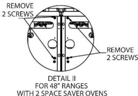
text_image
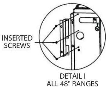
REMOVE 2 SCREWS REMOVE 2 SCREWS DETAIL II FOR 48" RANGES WITH 2 SPACE SAVER OVEN- For all 48" ranges install the left and right support brackets (part # 4523226 and 4523227) by re-inserting the 2 screws removed in step 1 and one additional screw (on both sides of the range).
text_image
INSERTED SCREWS DETAIL I ALL 48" RANGES-
Slide the salamander down into the support brackets installed in step 2, see figure 2. NOTE: On ranges with 2 space saver ovens, the center post must slide into the center channels built into the back of the unit.
-
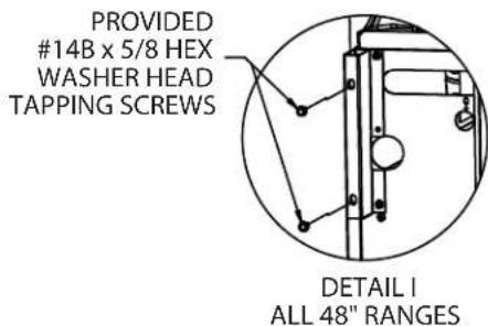
Once the salamander is in place, fasten it to the unit on both sides of the range with the provided #14B x 5/8 hex washer head tapping screws.
text_image
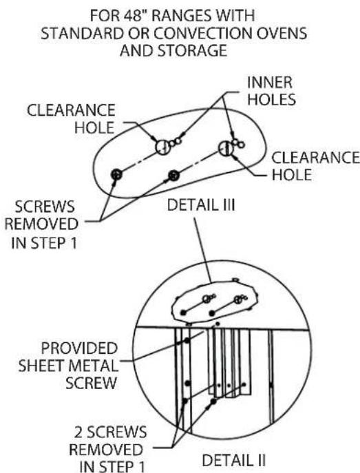
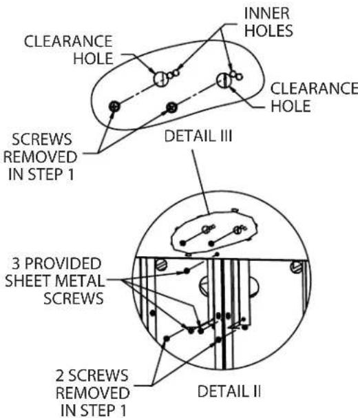
PROVIDED #14B x 5/8 HEX WASHER HEAD TAPPING SCREWS DETAIL I ALL 48" RANGES- For center support, (detail II) re-insert screws removed in step 1 or provided sheet metal screws as shown in detail II and III, inserting screws for detail III through clearance in back panel.
text_image
FOR 48" RANGES WITH STANDARD OR CONVECTION OVEN S AND STORAGE CLEARANCE HOLE INNER Holes CLEARANCE HOLE SCREWS REMOVED IN STEP 1 DETAIL III PROVIDED SHEET METAL SCREW 2 SCREWS REMOVED IN STEP 1 DETAIL IIFOR 48" RANGES WITH 2 SPACE SAVER OVENS
text_image
CLEARANCE HOLE INNER HOLES CLEARANCE HOLE SCREWS REMOVED IN STEP 1 DETAIL III 3 PROVIDED SHEET METAL SCREWS 2 SCREWS REMOVED IN STEP 1 DETAIL II- Re-insert screws removed in step 1 though clearance hole in back panel as shown:
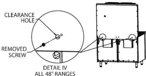
text_image
CLEARANCE HOLE REMOVED SCREW DETAIL IV ALL 48" RANGESModel GFIR60 - 60" Ranges
text_image
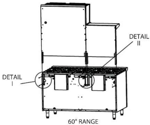
DETAIL I DETAIL II 60" RANGEFigure 3 – With area detail defined for 60 inch range.
NOTE: Instructions are for mounting the salamander on the right side, for mounting on the left side follow the same directions except use references 1, 2, 3, & 4 (to the left of detail II see below) in lieu of A, B, C, D for detail II in the following steps.
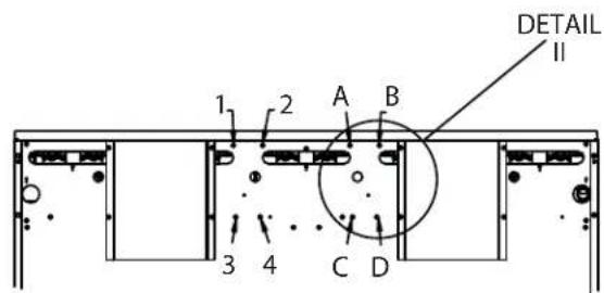
text_image
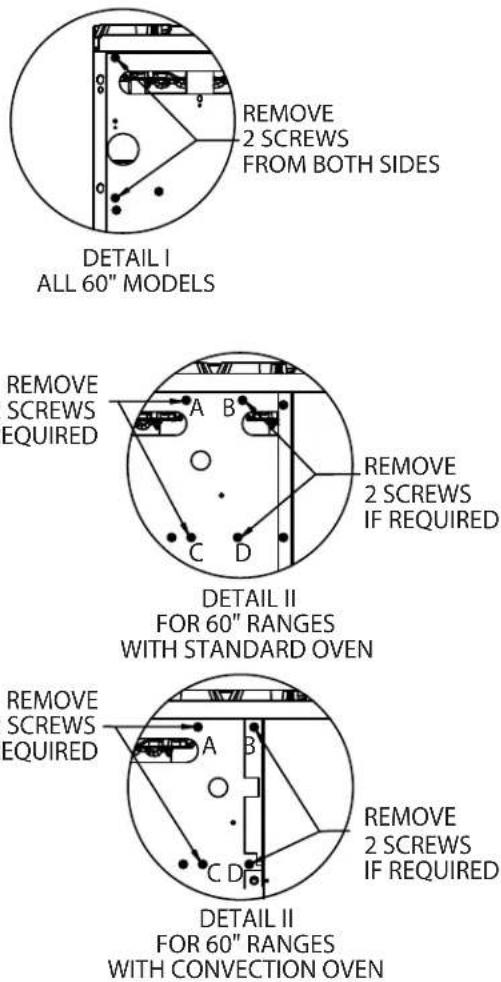
DETAIL II 1 2 A B 3 4 C D- Remove screws from back of oven on both sides of the range (detail I) and center (detail II) as shown:
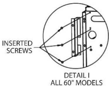
- Install the left and right support brackets (part # 4523226 and 4523227) using the 2 screws removed in step 1 (detail I) and one additional screw on both sides of the range, and center support bracket (part # 4523282) with the four screws removed in step 1 (detail II).
text_image
INSERTED SCREWS DETAIL I ALL 60" MODELS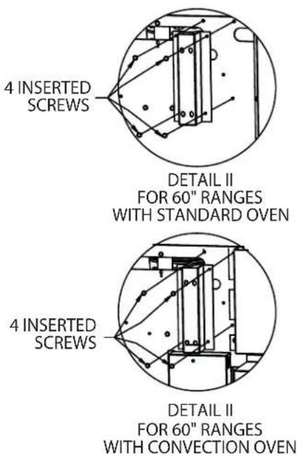
text_image
4 INSERTED SCREWS DETAIL II FOR 60" RANGES WITH STANDARD OVEN 4 INSERTED SCREWS DETAIL II FOR 60" RANGES WITH CONVECTION OVEN-
Slide the salamander down into the support brackets installed in step 2, see figure 3.
-
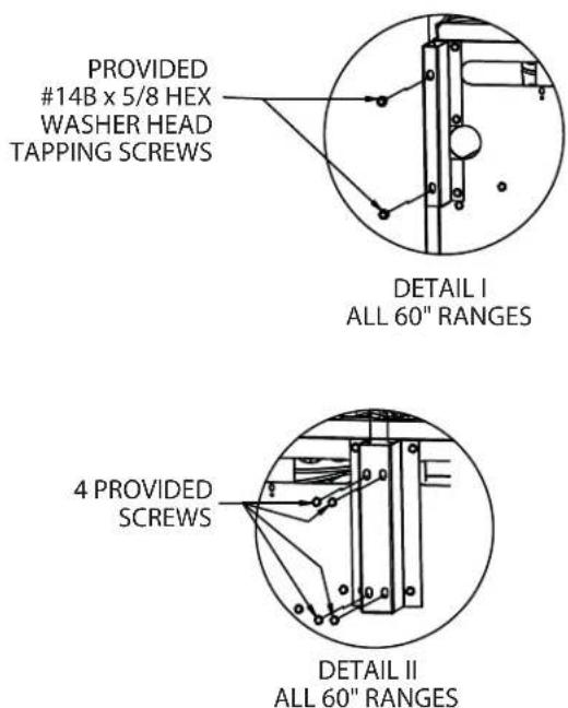
Once the salamander is in place, fasten it to the unit on both sides of the range with the provided #14B x 5/8 hex washer head tapping screws (detail I) and the center to the support bracket using 4 of the provided screws (detail II).
text_image
PROVIDED #14B x 5/8 HEX WASHER HEAD TAPPING SCREWS DETAIL I ALL 60" RANGES 4 PROVIDED SCREWS DETAIL II ALL 60" RANGESWall Or Counter Mounted Salamanders
Model GFIR36C
-
The appliance shall be located with respect to building construction and other equipment so as to permit access to the appliance. Such access and clearance may be necessary for service and cleaning.
-
Counter models are furnished with 4" (102mm) legs. Level the unit with a carpenter's level and make minor adjustments with the threaded leg feet. Ensure that the counter top can support the weight of the appliance prior to installation and is comprised of non-combustible material.
-
Provisions for gas connections, top or rear, should be taken into consideration at time of installation.
-
If the unit is to be mounted on a non-combustible wall contact the local authorities for local codes.
-
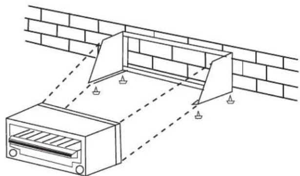
Position, level, and mark location of the assembled wall mount kit.
-
Drill wall (locating studs if necessary) to accept suitable fastening devices.
-
Drill the angle iron bars of the wall mounting kit to match those drilled in the wall.
-
Install wall mounting kit to wall.
-
Install and secure broiler with bolts supplied.
natural_image
Technical line drawing of a brick wall structure with two clamps and a gridded base (no text or symbols)Ventilation and Air Supply
For detailed recommendations, refer to the applicable code(s) in the country of destination. These appliances shall be installed in a room with sufficient ventilation to prevent the occurrence of hazardous concentrations of combustion by-products.
Proper ventilation is highly important for good operation. The ideal method of ventilation for a Salamander Broiler is the use of a properly designed canopy hood which should extend six inches (6", 152mm) beyond all sides of the appliance and six (6) feet six (6) inches (1981mm) from the floor.
A strong exhaust fan will create a vacuum in the room. For an exhaust system to work properly, replacement air must enter the room in which the vent is located. The amount of air which is exhausted must equal the amount entering, (make-up air).
All gas burners and pilots need sufficient air to operate and large objects should not be placed in front or on top of the broiler which would obstruct the air flow through the front of the broiler.
The following notes are intended to give general guidance. For detailed recommendations, refer to the applicable code(s) in the country of destination.
NOTE 1: The room containing the appliance is required to have a permanent air vent. The minimum effective area of the vent is related to the maximum rated heat input of the appliance and shall be 4.5 cm^2 per kW ( 2.04 × 10^-4 in^2 per BTU/H) in excess of 7 kW. (23,900 BTU/H).
NOTE 2: Air vents should be of such a size to compensate for the effects of any extract fan in the premises.
FOR YOUR SAFETY never place any type of object on top of the salamander broiler. The top of the broiler will exceed 1000° F (538° C). It could cause severe burns and/or fire and also will obstruct ventilation.
Clearances
Clearance must be 6" (152mm) at the sides and rear from combustible material. A clearance of 0.0" to noncombustible construction at the sides & rear is acceptable, for the Salamander.
This appliance is for use on non-combustible floors/counters only.
Burner Adjustments
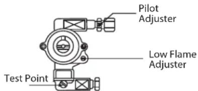
Minimum Flame Setting
- Set the gas tap to the low "A" position.
- Connect a U-gauge manometer to the pressure test nipple located downstream of the gas tap.
- With a fl at screwdriver, turn the adjuster on the tap body clockwise to reduce pressure or counter-clockwise to increase pressure. Set the pressure to correspond with Setting Pressure For "MIN" Tap Position" Table in DIMENSIONS AND SPECIFICATIONS section.
text_image
Pilot Adjuster Low Flame Adjuster Test PointWhen all the settings have been checked, remove the U-gauge manometer, replace the pressure test point screw and the front panel.
Hand these instructions to the user or purchaser for retention and instruct them in the efficient and safe operation of the appliance.
Tell the user of the location of the gas isolation cock for use in an emergency.
Safety concerns
It is the responsibility of the supervisor or equivalent person to ensure that users of this equipment wear suitable protective clothing and to draw attention to the fact that some parts will by necessity become very hot and will cause burns if touched accidentally.
Lighting The Salamander
NOTE: Ensure the gas supply to the appliance is turned "ON". During the initial ignition cycle, air must be purged from the gas line and thus it may take one to two minutes for the pilot burner to ignite.
- Push in the tap and turn it counter-clockwise to the Ignition Position "★
- Holding the tap fully in, light the pilot with a match or taper.
- When the pilot is lit, continue to hold the tap fully in for 20 seconds, then release it. IF the pilot goes out, wait for five (5) minutes, and then repeat from step 1.
- When the pilot is established, push the tap in again and turn it counter-clockwise to the full flame position \A^\ thus lighting the main burner.
- For low flame or simmer, push the tap in and turn it counter-clockwise to the low flame " position.
- To shut the burner off, turn the dial to the "symbol and the safety device will disengage within 60 seconds.
Operating Suggestions
- Turn the tap to the "●" position when the salamander is not in use.
- Clean the racks as soon as possible after cooking with tomato or vinegar based products that have a high acid content. These foods can cause pitting of the rack surface.
- Allow the salamander to preheat before adding product.
- Drain and clean the drip tray frequently. Excessive oil drain off in the pan can cause spillover.
Operating Controls

OFF
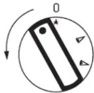
IGNITION
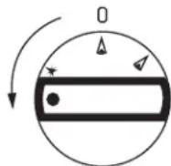
MAX
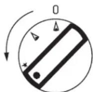
MIN
Daily
To avoid the risk of fi re, it is important that the food zone is cleaned of grease and debris prior to lighting the main burners.
The broiling rack and grease drawer should be wiped daily while still warm, using a heavy cloth or other grease absorbing material to remove grease and burnt food before they burn into the grid. Remove burnt materials, such as carbonized grease or food, with a stiff wire brush. DO NOT USE ANY TYPE OF STEEL WOOL. Small particles may be left on the rack surface and get into food products. The rack should be washed thoroughly using a wire brush and a hot, mild detergent or soap solution. Rinse with clear, warm water.
Monthly
Lubricate valves and bearings as required. Due to the usual location of the broiler that is mounted above a range with open tops, the heat from the open top will cause the lubrication grease inside the valves to dry out. When you notice that the valve is becoming harder to turn it is then time to have them greased. We suggest an Authorized Service Agent who is familiar with the appliance and working with natural and propane gas, to perform this type of work.
Exterior Cleaning
Establish a regular schedule. Any spills should be wiped off immediately.
- Wipe exposed, cleanable surface when cool with a mild detergent and hot water. Stubborn residue spots may be removed with a light weight non-metallic scouring pad. Dry thoroughly with a clean cloth.
- Stainless steel should be cleaned using a mild detergent, a soft cloth and hot water. If it is necessary to use a non-metallic scouring pad, always rub in the direction of the grain in the metal to prevent scratching. Use a water based stainless steel cleaner (such as Drackett Twinkle), if you want a high shine.
INSTRUCTIONS
D'INSTALLATION ET
D'UTILISATION
SALAMANDRES À INFRAROUGE GARLAND SÉRIE GF SENTRY





natural_image
Exterior view of a stainless steel kitchen appliance with ventilation grilles and control buttons (no text or symbols visible)POUR VOTRE SÉCURITÉ: NE PAS STOCKER NI UTILISER D'ESSENCE OU D'AUTRES VAPEURS OU LIQUIDES INFLAMMABLES À PROXIMITÉ DE CET APPAREIL OU DE TOUT AUTRE APPAREIL.
AVERTISSEMENT: UNE INSTALLATION, DES RÉGLAGES, DES MODIFICATIONS, DES RÉPARATIONS OU UN ENTRETIEN MAL FAITS PEUVENT CAUSER DES DOMMAGES MATÉRIELS, DES BLESSURES OU LA MORT. LIRE SOIGNEUSEMENT LES INSTRUCTIONS D'INSTALLATION, D'UTILISATION ET D'ENTRETIEN AVANT D'INSTALLER OU DE RÉPARER L'ÉQUIPEMENT.
NE PAS OBSTRUER LA CIRCULATION D'AIR DE COMBUSTION ET DE VENTILATION DE CET APPAREIL
LIRE TOUTES LES SECTIONS DU PRÉSENT MANUEL ET LE CONSERVER POUR S'Y REPORTER ULTÉRIEUREMENT.
CE PRODUIT A ÉTÉ HOMOLOGUÉ EN TANT QU'ÉQUIPEMENT PROFESSIONNEL DE CUISSON ET DOIT ÊTRE INSTALLÉ PAR DU PERSONNEL PROFESSIONNEL TEL QUE SPÉCIFIÉ.
DANS L'ÉTAT DU MASSACHUSETTS, CE PRODUIT DOIT ÊTRE INSTALLÉ PAR UN PLOMBIER OU UN MONTEUR D'INSTALLATION AU GAZ CERTIFIÉ
1177 Kamato Road, Mississauga, Ontario L4W 1X4
CANADA
Phone: 905-624-0260
Fax: 905-624-5669
General Inquires 1-905-624-0260
USA Sales 1-800-424-2411
Canadian Sales 1-888-442-7526
Canada or USA Parts/Service 1-844-724-2273
AVERTISSEMENT
INFORMATIONS IMPORTANTES .....20
INTRODUCTION ......22
INFORMATIONS GÉNÉRALES.....25
Implantation....25
text_image
4-1/4" [107mm] 1-7/16" [36mm] MONTAGE SUR CUISINIÈRE 19-3/8" [492mm] 35-7/16" [900mm]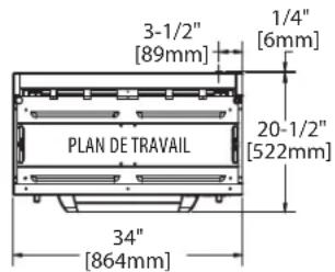
text_image
3-1/2" [89mm] 1/4" [6mm] 20-1/2" [522mm] PLAN DE TRAVAIL 34" [864mm]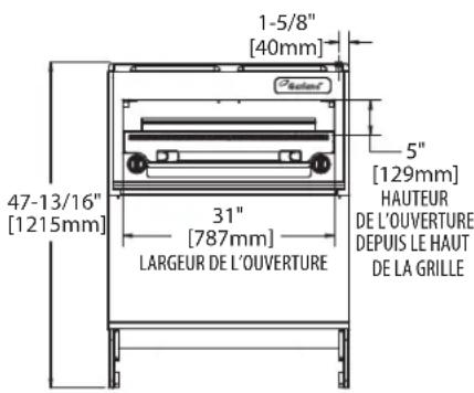
text_image
1-5/8" [40mm] 47-13/16" [1215mm] 31" [787mm] LARGEUR DE L'OUVERTURE 5" [129mm] HAUTEUR DE L'OUVERTURE DEPUIS LE HAUT DE LA GRILLE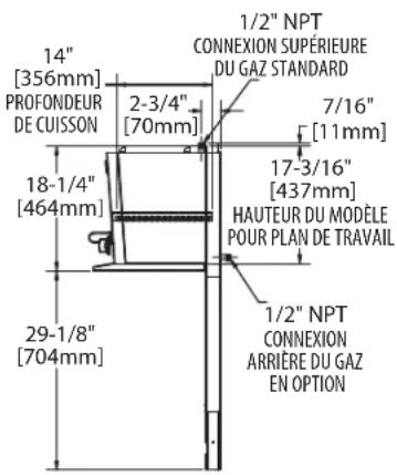
text_image
1/2" NPT CONNEXION SUPÉRIEURE DU GAZ STANDARD 14" [356mm] PROFONDEUR DE CUISSON 2-3/4" [70mm] 7/16" [11mm] 18-1/4" [464mm] 17-3/16" [437mm] HAUTEUR DU MODELE POUR PLAN DE TRAVAIL 29-1/8" [704mm] 1/2" NPT CONNEXION ARRIÈRE DU GAZ EN OPTION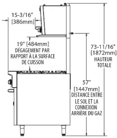
text_image
15-3/16" [386mm] 19" [484mm] DÉGAGEMENT PAR RAPPORT À LA SURFACE DE CUISSON 73-11/16" [1872mm] HAUTEUR TOTALE 57" [1447mm] DISTANCE ENTRE LE SOL ET LA CONNEXION ARRIÈRE DU GAZDIMENSIONS ET SPÉCIFICATIONS suite
| PIÈCE | DESCRIPTION QUANTITÉ 36Po | |
| 1 | 4.5" W.C 3/4"NPT, Regulator Natural Gas, supplied with Range 1 | |
| 3/4" ISO 7-1, Regulator Natural Gas, supplied with Range 1 | ||
| 10" W.C 3/4"NPT, Regulator Propane Gas, supplied with Range 1 | ||
| 3/4" ISO 7-1, Regulator Propane Gas, supplied with Range 1 | ||
| 2 Nipple, 3/4" NPT x 1/2" (one supplied with range) 3 | ||
| 3 Elbow, 90deg, 3/4" NPT (one supplied with range) 2 | ||
| 4 Unon, 3/4" NPT 2 | ||
| 5 3/4"CC x 3/4" NPT Straight Fitting 2 | ||
| 6 Bracket, Pipe Support | 1 | |
| 7 Clamp, Pipe Support Bracket | 1 | |
| 8 Reducing Elbow, 90deg, 3/4" NPT x 1/2" NPT | 1 | |
| 9 Nipple, 3/4" NPT x 6.5" | 1 | |
| 10 | Reducing Tee, 3/4" NPT x 3/4" NPT x 1" | 1 |
| 11 | Screw, #10-16 x 1/2" Hex, Washer Head, Teks Self-Drill/Tap (not shown) | 2 |
| 12 | Screw, #10-24 x 1/2" Pan Head, Self-Tap, Type F (not shown) | 2 |
| 13 | 6"W.C 3/4" NPT, Regulator Natural Gas, supplied with Salamander/Cheesemelter | 1 |
| 10"W.C 3/4" NPT, Regulator Propane Gas, supplied with Salamander/Cheesemelter | 1 | |
| 14 | Nipple, 3/4" NPT x 3.5" | 1 |
| 15 | Tubing 3/4" | 1 |
| PIÈCE DESCRIPTION | QUANTITÉ48 Po, 60 Po | |
| 1 Screw, #10-24 x 1/2" Pan Head, Self-Tap, Type F (not shown) 4 | ||
| 2 | 4.5" W.C 1"NPT, Regulator Natural Gas, supplied with Range 1 | |
| 1" ISO 7-1, Regulator Natural Gas, supplied with Range 1 | ||
| 10" W.C 1"NPT, Regulator Propane Gas, supplied with Range 1 | ||
| 1" ISO 7-1, Regulator Propane Gas, supplied with Range 1 | ||
| 3 | 6" W.C 3/4" NPT, Regulator Natural Gas, supplied with Salamander/Cheesemelter 1 | |
| 10" W.C 3/4" NPT, Regulator Propane Gas, supplied with Salamander/Cheesemelter 1 | ||
| 4 Nipple, 1" NPT x 2" (one supplied with range) 3 | ||
| 5 Nipple, 3/4" NPT x 6.5" 1 | ||
| 6 Elbow, 90deg, 3/4" NPT | 3 | |
| 7 Elbow, 90deg, 1" NPT (supplied with range) | 1 | |
| 8 Union, 1" NPT | 1 | |
| 9 Bracket, Pipe Support 48/60 | 2 | |
| 10 | Clamp, Pipe Support Bracket | 2 |
| 11 | Reducing Tee, 1" NPT x 1" NPT x 3/4" | 1 |
| 12 | Nipple, 3/4" NPT x 22.75" | 1 |
| 13 | Nipple, 3/4" NPT x 2" | 1 |
| 14 | Screw, #10-16 x 1/2" Hex, Washer Head, Teks Self-Drill/Tap (not shown) | 4 |
| 15 | Nipple, 3/4" NPT x 3.5" 1 | |
| 16 | Reducing Elbow, 90deg, 3/4" NPT x 1/2" NPT | 1 |
| 17 | 3/4"CC x 3/4" NPT Straight Fitting | 2 |
| 18 | Tubing 3/4" | 1 |
la sécurité d'abord
natural_image
Technical line drawing of a roof drainage system with two rectangular structures and a heater, mounted on a brick wall (no text or symbols)Ventilation Et Alimentation En Air
natural_image
Exterior view of a stainless steel kitchen grater with ventilation slots and control buttons (no text or symbols visible)PARA SU SEGURIDAD:
NO ALMACENE O UTILICE GASOLINA U OTROS VAPORES O LÍQUIDOS INFLAMABLES EN LAS CERCANÍAS DE ESTE O CUALQUIER OTRO ARTEFACTO.
ADVERTENCIA:
1177 Kamato Road, Mississauga, Ontario L4W 1X4
CANADA
Phone: 905-624-0260
Fax: 905-624-5669
General Inquires 1-905-624-0260
USA Sales 1-800-424-2411
Canadian Sales 1-888-442-7526
Canada or USA Parts/Service 1-844-724-2273
ADVERTENCIA:
text_image
4-1/4" [107mm] 1-7/16" [36mm] MONTAJE SOBRE ESTUFA 19-3/8" [492mm] 35-7/16" [900mm]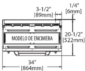
text_image
3-1/2" [89mm] MODELO DE ENCIMERA 34" [864mm] 1/4" [6mm] 20-1/2" [522mm]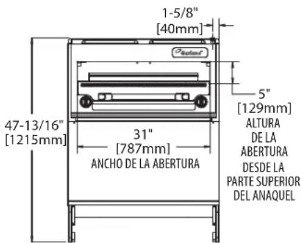
text_image
1-5/8" [40mm] 47-13/16" [1215mm] 31" [787mm] ANCHO DE LA ABERTURA 5" [129mm] ALTURA DE LA ABERTURA DESDE LA PARTE SUPERIOR DEL ANAQUEL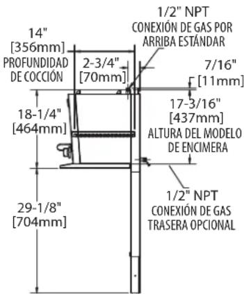
text_image
1/2" NPT CONEXIÓN DE GAS POR ARRIBA ESTÁNDAR 14" [356mm] PROFUNDIDAD DE COCCIÓN 2-3/4" [70mm] 7/16" [11mm] 18-1/4" [464mm] 17-3/16" [437mm] ALTURA DEL MODELO DE ENCIMERA 29-1/8" [704mm] 1/2" NPT CONEXIÓN DE GAS TRASERA OPCIONAL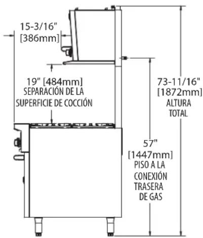
text_image
15-3/16" [386mm] 19" [484mm] SEPARACIÓN DE LA SUPERFICIE DE COCCIÓN 73-11/16" [1872mm] ALTURA TOTAL 57" [1447mm] PISO A LA CONEXIÓN TRASERA DE GAS| PIEZA DESCRIPCIÓN CANTIDAD (36") | ||
| 1 | 4.5" W.C 3/4"NPT, Regulator Natural Gas, supplied with Range 1 | |
| 3/4" ISO 7-1, Regulator Natural Gas, supplied with Range 1 | ||
| 10" W.C 3/4"NPT, Regulator Propane Gas, supplied with Range 1 | ||
| 3/4" ISO 7-1, Regulator Propane Gas, supplied with Range 1 | ||
| 2 Nipple, 3/4" NPT x 1/2" (one supplied with range) 3 | ||
| 3 Elbow, 90deg, 3/4" NPT (one supplied with range) 2 | ||
| 4 Union, 3/4" NPT | 2 | |
| 5 3/4"CC x 3/4" NPT Straight Fitting | 2 | |
| 6 Bracket, Pipe Support | 1 | |
| 7 Clamp, Pipe Support Bracket | 1 | |
| 8 Reducing Elbow, 90deg, 3/4" NPT x 1/2" NPT | 1 | |
| 9 Nipple, 3/4" NPT x 6.5" | 1 | |
| 10 | Reducing Tee, 3/4" NPT x 3/4" NPT x 1" | 1 |
| 11 | Screw, #10-16 x 1/2" Hex, Washer Head, Teks Self-Drill/Tap (not shown) | 2 |
| 12 | Screw, #10-24 x 1/2" Pan Head, Self-Tap, Type F (not shown) | 2 |
| 13 | 6"W.C 3/4"NPT, Regulator Natural Gas, supplied with Salamander/Cheesemelter | 1 |
| 10"W.C 3/4" NPT, Regulator Propane Gas, supplied with Salamander/Cheesemelter | 1 | |
| 14 | Nipple, 3/4" NPT x 3.5" | 1 |
| 15 | Tubing 3/4" | 1 |
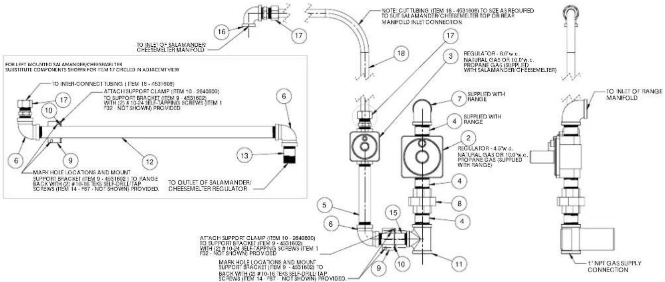
Kit Opcional De Interconexión De Gas # 4531606 (48"/60")
text_image
TO INLET OF SALAMANDER/ CHEESEMELTER MANIFOLD FOR LEFT MOUNTED SALAMANDER/CHEESEMELTER SUBSTITUTE COMPONENTS SHOWN FOR ITEM 17 CIRCLED IN ADJACENT VIEW TO INTER-CONNECT TUBING (ITEM 18 - 4531608) ATTACH SUPPORT CLAMP (ITEM 10 - 2640800) TO SUPPORT BRACKET (ITEM 9 - 4531602) WITH (2) #10-24 SELF-TAPPING SCREWS (ITEM 1 F32 - NOT SHOWN) PROVIDED MARK HOLE LOCATIONS AND MOUNT SUPPORT BRACKET (ITEM 9 - 4531602) TO RANGE BACK WITH (2) #10-16 TEKS SELF-DRILL TAP SCREWS (ITEM 14 - F57 - NOT SHOWN) PROVIDED. TO OUTLET OF SALAMANDER/ CHEESEMELTER REGULATOR NOTE: CUT TUBING (ITEM 18 - 4531608) TO SIZE AS REQUIRED TO SUT SALAMANDER/ CHEESEMELTER TOP OR REAR MANIFOLD INLET CONNECTION REGULATOR - 6.0W.c. NATURAL GAS OR 10.0W.c. PROpane GAS (SUPPLIED WITH SALAMANDER/ CHEESEMELTER) SUPPLIED WITH RANGE SUPPLIED WITH RANGE REGULATOR - 4.5W.c. NATURAL GAS OR 10.0W.c. PROpane GAS (SUPPLIED WITH RANGE) TO INLET OF RANGE MANIFOLD ATTACH SUPPORT CLAMP (ITEM 10 - 2640800) TO SUPPORT BRACKET (ITEM 9 - 4531602) WITH (2) #10-24 SELF-TAPPING SCREWS (ITEM 1 F32 - NOT SHOWN) PROVIDED MARK HOLE LOCATIONS AND MOUNT SUPPORT BRACKET (ITEM 9 - 4531602) TO BACK WITH (2) #10-16 TEKS SELF-DRILL TAP SCREWS (ITEM 14 - F57 - NOT SHOWN) PROVIDED. 1' NPI GAS SUPPLY CONNECTION| PIEZA | DESCRIPCIÓN | CANTIDAD(48"/60") |
| 1 Screw, #10-24 x 1/2" Pan Head, Self-Tap, Type F (not shown) 4 | ||
| 2 | 4.5" W.C 1"NPT, Regulator Natural Gas, supplied with Range 1 | |
| 1" ISO 7-1, Regulator Natural Gas, supplied with Range 1 | ||
| 10" W.C 1"NPT, Regulator Propane Gas, supplied with Range 1 | ||
| 1" ISO 7-1, Regulator Propane Gas, supplied with Range 1 | ||
| 3 | 6" W.C 3/4" NPT, Regulator Natural Gas, supplied with Salamander/Cheesemelter 1 | |
| 10" W.C 3/4" NPT, Regulator Propane Gas, supplied with Salamander/Cheesemelter 1 | ||
| 4 Nipple, 1" NPT x 2" (one supplied with range) 3 | ||
| 5 Nipple, 3/4" NPT x 6.5" 1 | ||
| 6 Elbow, 90deg, 3/4" NPT | 3 | |
| 7 Elbow, 90deg, 1" NPT (supplied with range) | 1 | |
| 8 Union, 1" NPT | 1 | |
| 9 Bracket, Pipe Support 48/60 | 2 | |
| 10 | Clamp, Pipe Support Bracket | 2 |
| 11 | Reducing Tee, 1" NPT x 1" NPT x 3/4" | 1 |
| 12 | Nipple, 3/4" NPT x 22.75" | 1 |
| 13 | Nipple, 3/4" NPT x 2" | 1 |
| 14 | Screw, #10-16 x 1/2" Hex, Washer Head, Teks Self-Drill/Tap (not shown) | 4 |
| 15 | Nipple, 3/4" NPT x 3.5" 1 | |
| 16 | Reducing Elbow, 90deg, 3/4" NPT x 1/2" NPT | 1 |
| 17 | 3/4"CC x 3/4" NPT Straight Fitting | 2 |
| 18 | Tubing 3/4" | 1 |