GEN-4000-iMM1E - Generator Mi-T-M - Free user manual and instructions
Find the device manual for free GEN-4000-iMM1E Mi-T-M in PDF.

User questions about GEN-4000-iMM1E Mi-T-M
0 question about this device. Answer the ones you know or ask your own.
Ask a new question about this device
Download the instructions for your Generator in PDF format for free! Find your manual GEN-4000-iMM1E - Mi-T-M and take your electronic device back in hand. On this page are published all the documents necessary for the use of your device. GEN-4000-iMM1E by Mi-T-M.
USER MANUAL GEN-4000-iMM1E Mi-T-M
natural_image
Abstract geometric logo design resembling the letter M, composed of stylized letters (no text or symbols)Mi-T-M®
CORPORATION
THANK YOU for purchasing a Mi-T-M product.
READ THIS MANUAL carefully to learn how to operate and service your machine correctly. Failure to do so could result in personal injury or equipment damage.
THIS MANUAL SHOULD BE CONSIDERED a permanent part of your machine and should remain with the machine when you sell it.
MEASUREMENTS in this manual are given in both metric and customary U.S. unit equivalents. Use only correct replacement parts and fasteners. Metric and inch fasteners may require a specific metric or inch wrench.
RIGHT HAND AND LEFT HAND sides are determined by facing the control panel end of the machine.
The SERIAL NUMBER is located in the Specification or Identification Numbers section. Accurately record all the numbers to help in tracing the machine should it be stolen. Your dealer also needs these numbers when you order parts. File the identification numbers in a secure place off the machine.
WARRANTY is provided from your dealer for customers who operate and maintain their equipment as described in this manual. The warranty is explained on the warranty certificate shown in this manual.
This warranty provides you the assurance that your dealer will back products where defects appear within the warranty period. Should the equipment be abused, or modified to change its performance beyond the original factory specifications, the warranty will become void.
THIS SPARK IGNITION SYSTEM COMPLIES WITH CANADIAN ICES-002. CE SYSTÈME D'ALLUMAGE PAR ÊTINCELLE EST CONFORME À LA NORME NMB-002 DU CANADA.
⚠ WARNING
⚠ WARNING: This product can expose you to chemicals including Lead, which is known to the State of California to cause cancer and birth defects or other reproductive harm. For more information go to www.P65Warnings.ca.gov
WARNING
⚠ WARNING: This product can expose you to chemicals including carbon monoxide, which is known to the State of California to cause birth defects or other reproductive harm. For more information go to www.P65Warnings.ca.gov
NOTICE
FEDERAL EMISSION COMPONENT DEFECT WARRANTY and CALIFORNIA EMISSION CONTROL WARRANTY are applicable to only those engines / generators complied with EPA (Environmental Protection Agency) and CARB (California Air Resources Board) emission regulations in the U.S.A.
NOTICE
To the engines / generators exported to and used in the countries other than the U.S.A., warranty service shall be performed by the distributor in each country in accordance with the standard Mi-T-M engine / generator warranty policy as applicable.
AIR INDEX
To show compliance with California emission regulations, a hang tag has been provided displaying the Air Index level and durability period of this engine.
The Air Index level defines how clean an engine's exhaust is over a period of time. A bar graph scaled from “0” (most clean) to “10” (least clean) is used to show an engine's Air Index level. A lower Air Index level represents cleaner exhaust from an engine.
The period of time (in hours) that the Air Index level is measured is known as the durability period. Depending on the size of the engine, a selection of time periods can be used to measure the Air Index level (see below).
Descriptive Term Applicable to Emissions Durability Period
Moderate: 50 hours (engine from 0 to 80 cc)
125 hours (engine greater than 80 cc)
Intermediate: 125 hours (engine from 0 to 80 cc)
250 hours (engine greater than 80 cc)
Extended: 300 hours (engine from 0 to 80 cc)
500 hours (engine greater than 80 cc)
Notice: This hang tag must remain on the engine or piece of equipment, and only be removed by the ultimate purchaser before operation.
CONTENTS
CONTENTS
INTRODUCTION 2
CONTENTS....4
SAFETY....5
CONTROLS 13
PREPARING THE GENERATOR....16
OPERATION....19
SERVICE....20
STORAGE 24
TROUBLESHOOTING....25
SPECIFICATIONS 26
ALL INFORMATION, ILLUSTRATIONS AND SPECIFICATIONS IN THIS MANUAL ARE BASED ON THE LATEST INFORMATION AVAILABLE AT THE TIME OF PUBLICATION. THE RIGHT IS RESERVED TO MAKE CHANGES AT ANY TIME WITHOUT NOTICE.
RECOGNIZE SAFETY INFORMATION
This is the safety alert symbol. When you see this symbol on your machine or in this manual, be alert to the potential for personal injury.
Follow recommended precautions and safe operating practices.

natural_image
Black triangular warning symbol with exclamation mark (no text or numbers)UNDERSTAND SIGNAL WORDS
A signal word--DANGER, WARNING or CAUTION--is used with the safety-alert symbol. DANGER identifies the most serious hazards.
DANGER or WARNING safety signs are located near specific hazards. General precautions are listed on CAUTION safety signs. CAUTION also calls attention to safety messages in this manual.
⚠️ DANGER
WARNING
CAUTION
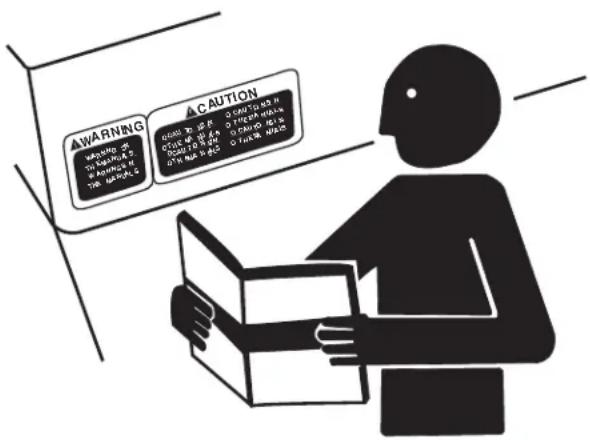
FOLLOW SAFETY INSTRUCTIONS
Carefully read all safety messages in this manual and safety signs on your machine. Keep safety signs in good condition. Replace missing or damaged safety signs. Be sure new equipment components and repair parts include the current safety signs. Replacement safety signs are available from your Mi-T-M Customer Service Representative.
Learn how to operate the machine and how to use controls properly. Do not let anyone operate without instruction.
Keep your machine in proper working condition. Unauthorized modifications to the machine may impair the function and/or safety and affect machine life.
If you do not understand any part of this manual and need assistance, contact your Mi-T-M Customer Service Representative.
text_image
AWARNING WARNING: TO BARRA 2 ONION: H THE BARRA 2 ACUTION GOOD OR GOOD OF THE BARRA GOOD OR GOOD OF THE BARRA GOOD TO GOOD OF THE BARRA O HEALTH AND O HEALTH AND O HEALTH AND O HEALTH ANDCARBON MONOXIDE - POISONOUS GAS
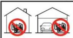
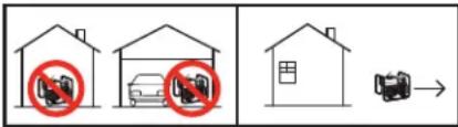
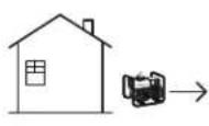
Use generator outdoors, away from open windows, vents, or doors. Keep generator at least 1 meter (3 feet) away from any structure or building during use.
Generator exhaust contains carbon monoxide - a poisonous gas that can kill you. You CAN NOT smell or see this gas.
Never use a generator in enclosed or partially-enclosed spaces. Generators can produce high levels of carbon monoxide very quickly. When you use a portable generator, remember that you cannot smell or see carbon monoxide. Even if you can't smell exhaust fumes, you may still be exposed to carbon monoxide.
If you start to feel sick, dizzy, or weak while using a generator, get to fresh air RIGHT AWAY. DO NOT DELAY. The carbon monoxide from

natural_image
Abstract black-and-white graphic of a bird-like figure with a circular element, set against a textured gray background (no text or symbols)generators can rapidly lead to full incapacitation and death.
If you experience serious symptoms, get medical attention immediately. Inform medical staff that carbon monoxide poisoning is suspected. If you
DANGERDANGERPELAGRO
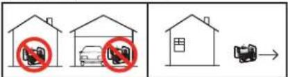
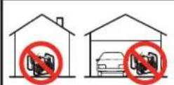
Using a generator indoors CAN KILL YOU IN MINUTES. Generator exhaust contains carbon monoxide. This is a poison you cannot see or smell.
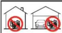
NEVER use inside a home or garage, EVEN IF doors and windows are open.
Only use OUTSIDE and far away from windows, doors, and vents.
experienced symptoms while indoors, have someone call the fire department to determine when it is safe to re-enter the building.
Never operate the generator in an explosive atmosphere, near combustible materials or where ventilation is not sufficient to carry away exhaust fumes. Exhaust fumes can cause serious injury or death.
NEVER use a generator indoors, including in homes, garages, basements, crawl spaces, and other enclosed or partially-enclosed areas, even with ventilation. Opening doors and windows or using fans will not prevent carbon monoxide build-up in the home.
Follow the instructions that come with your generator. Locate the unit outdoors and away from doors, windows, and vents that could allow the carbon monoxide gas to come indoors.
ONLY run generator outdoors and away from air intakes.
NEVER run generator inside homes, garages, sheds, or other semi-enclosed spaces. These spaces can trap poisonous gases EVEN IF you run a fan or open doors and windows.
If you start to feel sick, dizzy, or weak while using the generator, shut if off and get fresh air RIGHT AWAY. See a doctor. You may have carbon monoxide poisoning.
Install battery-operated carbon monoxide alarms or plug-in carbon monoxide alarms with battery back-up in your home, according to the manufacturer's installation instructions. The carbon monoxide alarms should be certified to the requirements of the latest safety standards for carbon monoxide alarms. (UL 2034, IAS 6-96, or CSA 6.19.01).
Test your carbon monoxide alarm frequently and replace dead batteries.
SAFETY WARNING WHEN REFUELING
Gasoline is extremely flammable and its vapors can explode if ignited.
Observe all safety regulations for the safe handling of fuel. Handle fuel in safety containers. If the container does not have a spout, use a funnel.
Do not overfill the fuel tank, leave room for the fuel to expand.
Do not refill fuel tank while the engine is running. Before refueling the generator, turn it off and let it cool down. Gasoline spilled on hot engine parts could ignite.
Fill the tank only on an area of bare ground. While fueling the tank, keep heat, sparks and open flame away. Carefully clean up any spilled fuel before starting engine.
Always fill fuel tank in an area with plenty of ventilation to avoid inhaling dangerous fumes.
NEVER store fuel for your generator in the home. Gasoline, propane, kerosene, and other flammable liquids should be stored outside of living areas in properly-labeled, non-glass safety containers. Do not store them near a fuel-burning appliance, such as a natural gas water heater in a garage. If the fuel is spilled or the container is not sealed properly, invisible vapors from the fuel can travel along the ground and can be ignited by the appliance's pilot light or by arcs from electric switches in the appliance.
BATTERY
- Do not expose battery to temperatures above 60 C (140 F).
- Do not reverse the positive (+) or negative (-) terminals or short-circuit the battery in any way.
- Do not allow charge voltages in excess of 40 volts.
- If the battery becomes hot to the touch, stop charging. Allow battery to cool before charging.
- Do not open, disassemble or modify the battery in any way.
- Do not connect the battery to other batteries in any way.
- Do not over-discharge the battery. It may damage the battery or shorten the battery life.
- A flammable hazard may exist if the battery is physically damaged.
- Failure to follow these instructions may present risk of explosions, fire or high temperatures.
natural_image
Abstract black starburst graphic on white background (no text or symbols)
natural_image
Silhouette of a person refueling a fuel pump with a no-smoking symbol (no text or labels)ELECTRICAL HAZARDS
THERE IS A PERMANENT CONDUCTOR BETWEEN THE GENERATOR (STATOR WINDING) AND THE FRAME.
CAUTION: NOT FOR INTERRUPTING CURRENT.
This product must be grounded. If it should malfunction or breakdown, grounding provides a path of least resistance for electric current to reduce the risk of electric shock.
DANGER - IMPROPER CONNECTION OF THE EQUIPMENT-GROUNDING CONDUCTOR CAN RESULT IN A RISK OF ELECTROCUTION. CHECK WITH A QUALIFIED ELECTRICIAN OR SERVICE PERSON IF YOU ARE INDOUBT AS TO WHETHER THE UNIT IS PROPERLY GROUNDED.
This generator is equipped with a grounding terminal for your protection. Always complete the ground path from the generator to an external ground source as instructed in the section labeled "Grounding Instructions" in the Preparation section of this manual.
The generator is a potential source of electrical shock if not kept dry. Keep the generator dry and do not use in rain or wet conditions. To protect from moisture, operate it on a dry surface under an open, canopy-like structure. Dry your hands if wet before touching the generator.
Plug appliances directly into the generator. Or, use a heavy duty, outdoor-rated extension cord that is rated (in watts or amps) at least equal to the sum of the connected appliance loads. Check that the entire cord is free of cuts or tears and that the plug has all three prongs, especially a grounding pin.
NEVER try to power the house wiring by plugging the generator into a wall outlet, a practice known as "back feeding". This is an extremely dangerous practice that presents an electrocution risk to utility workers and neighbors served by the same utility transformer. It also bypasses some of the built-in household circuit protection devices.
If you must connect the generator to the house wiring to power appliances, have a qualified electrician install the appropriate equipment in accordance with local electrical codes. Or, check with your utility company to see if it can install an appropriate power transfer switch.
For power outages, permanently installed stationary generators are better suited for providing backup power to the home. Even a properly connected portable generator can become overloaded. This may result in overheating or stressing the generator components, possibly leading to a generator failure.
natural_image
Black-and-white illustration of a hand with a lightning bolt and smoke trail, symbolizing electrical hazard (no text or symbols)IMPORTANT SAFETY INSTRUCTIONS

WARNING: TO REDUCE THE RISK OF INJURY, READ THIS OPERATOR'S MANUAL COMPLETELY BEFORE USING. WHEN USING THIS PRODUCT, THE FOLLOWING BASIC PRECAUTIONS SHOULD ALWAYS BE FOLLOWED:
- Read all the instructions before using the product.
-
Do not enclose the generator nor cover it with a box. The generator has a built-in forced air cooling system, and may become overheated if it is enclosed. If generator has been covered to protect if from the weather during non use, be sure to remove it and keep it well away from the area during generator use.
-
Operate the generator on a level surface. It is not necessary to prepare a special foundation for the generator. However, the generator will vibrate on an irregular surface, so choose a level place without surface irregularities.
If the generator is tilted or moved during operation, fuel may spill and/or the generator may tip over, causing a hazardous situation.
Proper lubrication cannot be expected if the generator is operated on a steep incline or slope. In such a case, piston seizure may occur even if the oil is above the upper level.
-
Pay attention to the wiring or extension cords from the generator to the connected device. If the wire is under the generator or in contact with a vibrating part, it may break and possibly cause a fire, generator burnout, or electric shock hazard. Replace damaged or worn cords immediately.
-
Do not operate in rain, in wet or damp conditions, or with wet hands. The operator may suffer severe electric shock if the generator is wet due to rain or snow.
-
If wet, wipe and dry it well before starting. Do not pour water directly over the generator, nor wash it with water.
-
Be extremely careful that all necessary electrical grounding procedures are followed during each and every use. Failure to do so can be fatal.
-
NEVER try to power the house wiring by plugging the generator into a wall outlet, a practice known as "back feeding". This is an extremely dangerous practice that presents an electrocution risk to utility workers and neighbors served by the same utility transformer. It also bypasses some of the built-in household circuit protection devices.
If you must connect the generator to the house wiring to power appliances, have a qualified electrician install the appropriate equipment in accordance with local electrical codes. Or, check with your utility company to see if it can install an appropriate power transfer switch.
- No smoking while charging a battery. The battery emits flammable hydrogen gas, which can explode if exposed to electric arcing or open flame. Keep the area well-ventilated and keep open flames / sparks away when charging a battery.
text_image
AUGA RATING ACC. RATINGIMPORTANT SAFETY INSTRUCTIONS
- Engine becomes extremely hot during and for some time after operation. Keep combustible materials well away from generator area. Be very careful not to touch any parts of the hot engine especially the muffler area or serious burns may result.
- Keep children and all bystanders at a safe distance from work area.
- It is absolutely essential that you know the safe and proper use of the power tool or appliance that you intend to use. All operators must read, understand and follow the tool / appliance owners manual. Tool and appliance applications and limitations must be understood. Follow all directions given on labels and warnings. Keep all instruction manuals and literature in a safe place for future reference.
- Use only "LISTED" extension cords. When a tool or appliance is used outdoors, use only extension cords marked "For Outdoor Use". Extension cords, when not in use should be stored in a dry and well ventilated area.
- Always disconnect tools or appliances when not in use, before servicing, adjusting, or installing accessories and attachments.
text_image
A Printing ACutionSAVE THESE INSTRUCTIONS
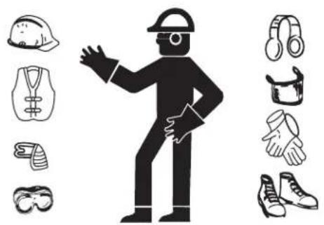
WEAR PROTECTIVE CLOTHING
Wear close fitting clothing and safety equipment appropriate to the job.
Wear a suitable hearing protective device such as ear-muffs or earplugs to protect against objectionable or uncomfortable loud noises.
Operating equipment safely requires the full attention of the operator. Do not wear radio or music headphones while operating machine.
natural_image
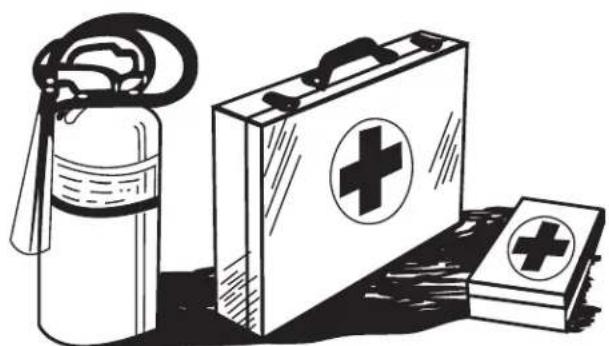
Silhouette of a person in protective gear with various safety and equipment icons (no text or symbols)PREPARE FOR EMERGENCIES
Keep a first aid kit and fire extinguisher handy.
Keep emergency numbers for doctors, ambulance service, hospital and fire department near your telephone.
Be prepared if a fire starts.
natural_image
Illustration of first aid kit, fire extinguisher, and first aid kit with cross symbols (no text or labels)INSPECT GENERATOR
Be sure all covers, guards and shields are tight and in place.
Locate all operating controls and safety labels.
Inspect power cord for damage before using. There is a hazard of electrical shock from crushing, cutting or heat damage.
SERVICE GENERATOR SAFELY
Before servicing the generator, disconnect all equipment and allow unit to cool down.
Service generator in a clean dry flat area.
Make sure the engine is stopped before starting any maintenance servicing or repair.
⚠ WARNING
WARNING: Cancer and Reproductive Harm — www.P65warnings.ca.gov/
SHOCK: A generator is a potential shock hazard which can result in serious injury or death. Generator must be kept dry and MUST be grounded before use. See operators manual for specific instructions.
• Always keep generator three (3) feet from any structure.
EXPLOSIVE FUEL: Gasoline is extremely flammable and its vapors can explode if ignited causing serious injury or death.
- Do NOT fill fuel tank while engine is hot or running.
ADVERTENCIA
• Always allow for fuel expansion
- Do not fill while running
Add fresh, unleaded fuel and stabilizer
FLASHING RED INDICATOR = Automatic Shutoff Event. Leave area immediately and relocate to an open outdoor area. Ventilate area thoroughly before occupying again. Ensure the generator is located in an open outdoor area. MOVE TO FRESH AIR AND GET MEDICAL HELP IF SICK, DIZZY OR WEAK
CONSTANT YELLOW INDICATOR = System Fault. Contact Dealer.

SYSTÈME D'ARRÊT POUR DÉTECTION DE MONOXYDE DE CARBONE EN SERVICE.
Using a generator indoors CAN KILL YOU IN MINUTES. Generator exhaust contains carbon monoxide. This is a poison you cannot see or smell.

NEVER use inside a home or garage, EVEN IF doors and windows are open.

Only use OUTSIDE and far away from windows, doors, and vents.
DANGER
text_image
Technical diagram of a portable gas stove with numbered components for identification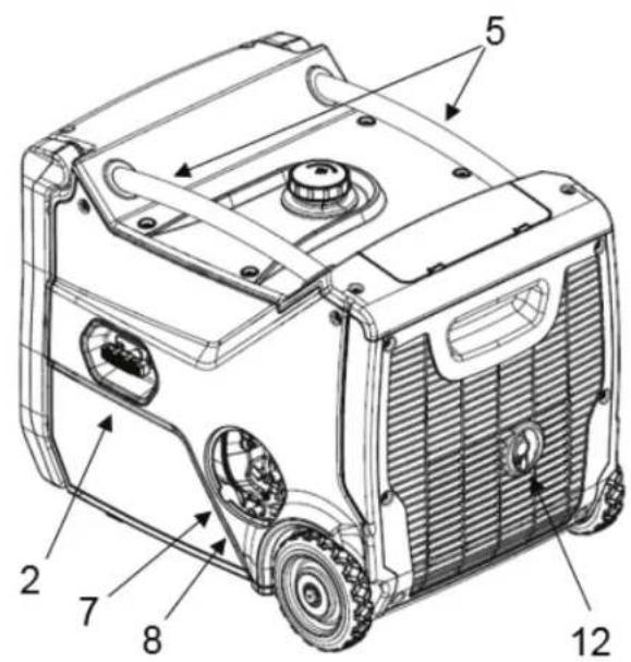
text_image
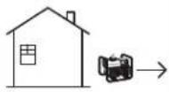
Technical diagram of a portable electric vehicle with numbered components labeled 2 through 12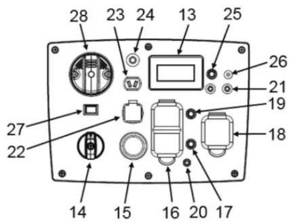
text_image
28 23 24 13 25 26 21 19 18 27 22 14 15 16 20 17- Fuel Cap
- Recoil Starter
- Panel LED Lights
- Fold-down Handle
- Carrying Handles
- Tool Compartment
- Oil Gauge / Oil Fill*
- Oil Drain*
- Air Filter Assembly**
- Spark plug**
* Behind Service Access Door
** Behind Side Panel
- Battery**
- Spark Arrestor
- LCD Smart Display
- Generator Switch
- Electric Starter
- Receptacle - 120 VAC duplex GFCI
- AC Circuit Breaker
- Receptacle - 120 VAC
- Main AC Circuit Breaker
-
Ground Terminal
-
Parallel Receptacles
- Receptacle - USB double
- Receptacle - 12VDC 8.3A
- DC Circuit Breaker
- Overload Reset Button
- Trickle Charger Port
- Idle Control Switch
- CO Detector
CONTROLS
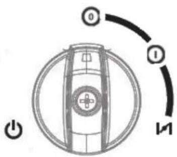
GENERATOR SWITCH
Turn the generator switch to the choke position when starting the engine. Turn the generator switch to the on position "I" once it has been started. To turn off the generator, turn the generator switch to the off "0" position.
LCD SMART DISPLAY
The generator is equipped with a multifunction smart LCD display to monitor real-time power output, fuel usage, and provide the user with information alerts relating to some basic service & fault scenarios.
- Power usage – Up to 6 bars shown with range between 0% and 100% load
- Indicator symbols – Oil service, overload, low oil level, low battery voltage
- Fuel level – Up to 6 bars shown with range between 0% and 100% fuel level
- Meter readings - AC voltage, frequency, DC battery voltage, operating hours*.
*The hours display automatically alternates between two readings:
a. With arrow showing – remaining hours based on current load and fuel remaining.
b. Without arrow showing – total accumulated hours from new.
LOW FUEL LEVEL INDICATOR
When the fuel level drops below 0.3 gal (1.2 L) the first fuel level bar will flash. If the unit is running, the remaining hours indicator will count down to 0 hrs before the unit shuts down. If the unit is started with less than 0.3 gal (1.2 L), the first bar will flash, and the remaining hours will show 0 hrs.
SERVICE INDICATOR
The service indicator will be displayed for 1hr when the accumulated hours reach the following milestones - 20hrs, 100hrs, and then every 100hrs thereafter.
OVERLOAD INDICATOR
The overload indicator will illuminate when there is a short circuit in a connected load, or the generator is overloaded.
LOW OIL LEVEL INDICATOR
The low oil level indicator will illuminate, and the unit will shut down when there is an insufficient amount of oil in the crankcase
LOW BATTERY VOLTAGE INDICATOR
The low battery indicator will illuminate when the battery voltage drops below 11.0 volts. The unit may not start using the electric start, but can still be started using the recoil start.
text_image
0 1 M
text_image
0% 100% 120.0 60.2 13.2 0.2 E F 2 V Hz V H 3 4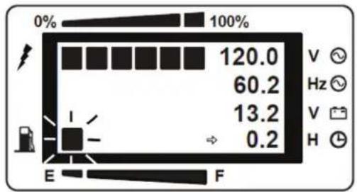
text_image
0% 100% 120.0 60.2 13.2 0.2 E F V ✓ Hz ✓ V ✓ H ✓PARALLEL CONNECTIONS
Two parallel ready generators can be connected together to increase the total power available to a load by using the parallel receptacles. The system seamlessly matches frequency and automatically distributes the load to each generator so one is not overloaded. Follow the parallel kit (sold separately) instructions for connection and use of a parallel kit.
ELECTRIC STARTER
Push the start button to crank the engine using the electric start and release it once the engine starts.
IDLE CONTROL
This generator is equipped with an idle control switch. When in the on position "I" the engine will vary speed to match the required power output to conserve fuel, and reduce wear and noise.
Note: If loads requiring intermittent power, or multiple large loads are connected, turn the electronic speed control switch off "O" to avoid possible engine stall. To avoid extended warmup time, keep the electronic speed control off until normal operating temperatures have been reached.
OVERLOAD RESET BUTTON
This button can be used to clear an overload condition without the need to stop and restart the unit.
AC/DC CIRCUIT BREAKERS
The generator comes equipped with AC (1) and DC (2) circuit breakers that protect the unit and the load from short circuit or overload conditions. If the circuit breaker opens, determine why the circuit breaker tripped before closing the circuit breaker.

WARNING: DO NOT PUT FOREIGN OBJECTS INTO THE PLUG RECEPTACLE.

CAUTION: DO NOT PLUG MORE THAN TWO APPLIANCES INTO THE GENERATOR AT A TIME.

CAUTION: IF CIRCUIT BREAKER CONTINUES TO TRIP, CHECK APPLIANCE FOR DEFECT. IF GENERATOR IS MALFUNCTIONING, SEE YOUR AUTHORIZED MI-T-M SERVICE CENTER.

NEVER INTERFERE WITH THE OPERATION OF THE CIRCUIT BREAKER KNOB OR KEEP PUSHING IT IN THE "ON" POSITION.
120 VAC, 20 AMP, GFCI DUPLEX
The 120 VAC duplex receptacle is protected against overload by a 20 Amp push to reset circuit breaker. It also provides protection via a Ground Fault Circuit Interruptor (GFCI) with press to Test and Reset buttons. Use the receptacle to power a NEMA 5-20, 120 VAC, single phase, 60 Hz electrical load requiring 20 Amps of current.


natural_image
Pure mechanical component diagram without any text, numbers, or symbols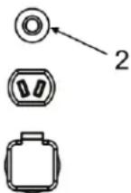
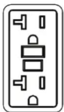
Use only high quality, well insulated, 3-wire grounded cords rated for 125 V at 20 Amps (or greater). Keep extension cords as short as possible (less than 15 feet) to prevent voltage drop and overheating of wires.
120 VAC, 30 AMP, LOCKING
The 120 VAC locking outlet is protected against overload by a 30 Amp push to reset circuit breaker.
Use a NEMA L5-30 plug with this receptacle (rotate to lock or unlock). Use the receptacle to power a 120 VAC, single phase, 60 Hz, single phase, 60 Hz electrical load.
12 VOLT DC
The generator comes equipped with a 12 volt DC output capable of providing 8.3 Amps of current, via the supplied 12 volt charging cable.
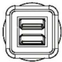
USB RECEPTACLES
The generator comes equipped with a double USB receptacle. The top is a 5V 1A USB port and the bottom is a 5V 2.1A USB port.
LOW OIL LEVEL SHUTDOWN
The generator is equipped with a low oil level shutdown that is designed to protect the engine from damage caused by an insufficient amount of oil in the crankcase. When the oil level in the crankcase falls below the safe operating limit, the low oil level light will illuminate and the engine will automatically shutdown.
CO DETECTOR (SHUT OFF SYSTEM)
The (carbon monoxide) CO Detector monitors the accumulation of CO gas while the generator is running and will shut off the engine if the levels become dangerously high. The CO Detector on this generator is not a substitute for an indoor CO alarm.
Whenever the CO Detector has shut off the engine there will be a light on the control panel that indicates the reason. Read the CO Action Label for the next steps to take.
If the CO Detector light is flashing "red" you must leave the area immediately and relocate to an open outdoor area. Ventilate the area thoroughly before occupying again. Ensure the generator is located in an open outdoor area with the exhaust pointed away from occupied structures. If anyone experiences dizziness, headaches, nausea, or tiredness get to fresh air immediately and seek medical attention.
If the CO Detector light is a constant "yellow" then a system fault has occurred, or it is indicating that it has reached the end of its life. This fault can only be diagnosed and repaired by an Authorized Service Provider.
The CO Detector monitors the accumulation of CO gas from all sources in the area around the generator. If the CO Detector light is flashing "red" this is not an error and safety measures must be taken immediately.
Note: Tampering with the CO Detector could result in hazardous conditions and must be avoided.
Note: The generator must not be operated in ambient temperatures greater than 131^ F ( 55^ C) as this can damage the CO Detector.


natural_image
Simple line drawing of a square frame with two internal rectangular slots, no text or symbols present.CARRIAGE BRACKETS
The generator has 4 red carriage brackets fitted underneath the base to prevent damage caused by rough handling during transit.

IMPORTANT- THESE BE MUST BE REMOVED BEFORE USE, OTHERWISE THE UNIT WILL VIBRATE EXCESSIVELY AND DAMAGE MAY OCCUR.
To remove the carriage brackets:
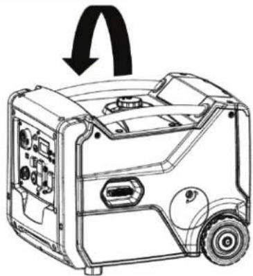
- Gently place the generator on its side (with the recoil handle facing up). Place some packaging foam under the generator to prevent damage.
- Using the wrench provided, remove the 4 nuts (1) and the 4 red carriage brackets (2). The studs securing the carriage brackets can remain in place.
BATTERY
The generator is equipped with an internal lithium-ion battery mounted in the battery holder. The battery is disconnected and must be connected before first use.
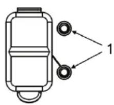
To access the battery:
- Unscrew the 2 fasteners (1) at the top of the side panel. Note that they are captive fasteners and cannot be removed from the side panel.
- Pull the captive fasteners in the direction shown (2) to release the top of the side panel.
- Pull the panel until the hidden fasteners (3) are pulled apart.

IMPORTANT, STOP PULLING ONCE THE FASTENERS (3) ARE PULLED APART, OTHERWISE THE TABS AT THE BOTTOM ON THE SIDE PANEL COULD BE DAMAGED.
- To remove the side panel completely, lift off in a vertical direction (4) to release the bottom tabs.
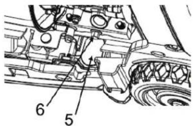
To connect the battery:
- The positive battery cable (5) is already connected.
- Attach the cable with the black cap to the negative battery terminal (6).
- To make the connection easier, the battery can be removed by releasing the rubber battery strap.
Reattach the side panel in reverse order before first use.
OPTIMAL GENERATOR OPERATING CONDITIONS
• Temperature: 23°F to 104 °F (-5°C to 40°C)
• Humidity below 95%
- Height above sea level: < 3000 feet (900 m). If the height of the operating area is over 900 m high, output power will be reduced.
Standard operating conditions are 77^ F ( 25^ C) and 40% humidity. Generator power may be reduced due to different ambient conditions and other factors such as fuel quality.
natural_image
Line drawing of a portable gas generator with wheels and control panel (no text or symbols)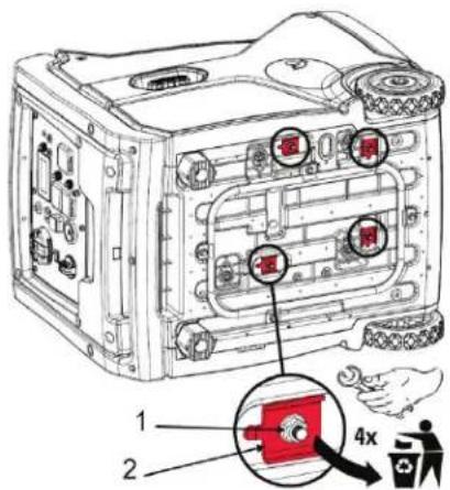
text_image
1 2 4x
text_image
Technical diagram of a portable gas stove with numbered components and directional arrows indicating assembly or status.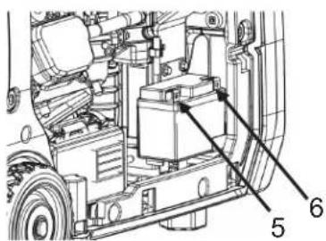
text_image
Technical diagram of a vehicle's internal components with numbered labels pointing to specific parts.CONNECTION TO HOUSEHOLD POWER SUPPLY
This generator must be installed in accordance with all applicable local laws and electrical codes. The generator must be isolated from the utility and the connection must be verified by a qualified electrician.
GROUNDING INSTRUCTIONS
This product must be grounded. If it should malfunction or breakdown, grounding provides a path of least resistance for electric current to reduce the risk of electric shock.

DANGER - IMPROPER CONNECTION OF THE EQUIPMENT-GROUNDING CONDUCTOR CAN RESULT IN A RISK OF ELECTROCUTION. CHECK WITH A QUALIFIED ELECTRICIAN OR SERVICE PERSON IF YOU ARE IN DOUBT AS TO WHETHER THE UNIT IS PROPERLY GROUNDED.
The ground terminal on the frame must always be used to connect the generator to a suitable ground source. The ground path should be made with #8 size wire. Connect the grounding wire securely to the ground terminal. Connect the other end of the wire securely to a suitable ground source.
The National Electric Code contains several practical ways in which to establish a good ground source. Examples given below illustrate a few of the ways in which a good ground source may be established.
A metal underground water pipe in direct contact with the earth for at least 10 feet can be used as a grounding source. If an pipe is unavailable, an 8 foot length of pipe or rod may be used as the ground source. The pipe should be 3/4 inch trade size or larger and the outer surface must be noncorrosive. If a steel or iron rod is used it should be at least 5/8 inch diameter and if a nonferrous rod is used it should be at least 1/2 inch diameter and be listed as material for grounding. Drive the rod or pipe to a depth of 8 feet. If a rock bottom is encountered less than 4 feet down, bury the rod or pipe in a trench. All electrical tools and appliances operated from this generator, must be properly grounded by use of a third wire or be “Double Insulated”.
It is recommended to:
- Use electrical devices with 3 prong power cords.
- Use an extension cord with a 3 hole receptacle and a 3 prong plug at the opposite ends to ensure continuity of the ground protection from the generator to appliance.
We strongly recommend that all applicable federal, state and local regulations relating to grounding specifications be checked and followed.
AC USAGE
Do NOT overload the generator. Exceeding the rated power of the generator can damage the generator and the electrical devices connected to it.
Motor-driven devices require a large starting current. Make sure that the total power requirement of these types of loads
natural_image
Black-and-white warning sign showing a hand breaking through a lightning bolt symbol (no text or numbers present)does not exceed the rated power of the generator.
When the generator is used to power multiple loads or electric appliances, start by connecting the appliance with the highest starting power requirements, followed by the second highest and ending with the lowest.
HIGH ALTITUDE KIT
At higher altitudes, the standard air-fuel mixture is too rich and will cause decreased performance and increased fuel consumption. A rich mixture will also foul the spark plug and make starting difficult. Operation at higher altitudes for extended periods of time may increase emissions.
Proper operation can be ensured by installing an altitude kit when required. High altitude kits should be installed by a qualified technician. Contact an authorized service provider if the portable generator will be operated at altitudes greater than 3000 feet (0.9 km) above sea level.
Note: At elevations greater than 8000 feet above sea level, the engine may experience decreased performance even with the high altitude kit installed.
| Recommended Lubricant Viscosities for Ambient Temperature | ||||
| Oil Viscosities | °C °F | |||
| Min Max Min | Max | |||
| SAE 0W-40 -40 | 40 -40 | 104 | ||
| SAE 5W-40 -30 | 50 -22 | 122 | ||
| SAE 10W-30 - 18 | 40 0 | 104 | ||
| SAE 15W-40 | -10 | 50 | 14 | 122 |
PRE-OPERATION
CHECK ENGINE OIL
Always check the engine oil with the generator on a level surface and with the engine stopped.
- Open the service access door and remove the oil level gauge (1) and wipe clean.
- Check the oil level by re-inserting the oil level gauge (do not screw in tight).
- If the oil level is low (3), add the recommended engine oil, using the funnel supplied, until the oil level reaches the upper mark (2) on the oil level gauge. Use the chart below to determine which viscosity oil to use.
- After adding oil, install and tighten the oil level gauge (1) and close the service door.
Note: Non-detergent and 2-stroke engine oils will damage the engine and must not be used.
CHECK FUEL LEVEL
- Check the fuel level gauge (2).
- If the fuel level is low, remove fuel cap (1).
- Check the strainer. If the strainer is dirty, clean the strainer. Refer to Fuel Tank Cap and Strainer – Clean for instructions.
- Add fuel. The use of a fuel stabilizer is highly recommended as the unit may sit for long periods of time before needed.
- Install the fuel cap after fueling.
To avoid personal injury always use caution when you are adding fuel:
- Fuel the generator in a well-ventilated area.
• Always stop the engine before fueling. - Always fill with the generator on a level surface.
- Allow the engine to cool before fueling.
text_image
Technical diagram of a lawn mower with labeled parts and mechanical assembly details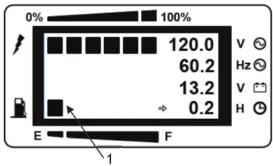
text_image
0% 100% 120.0 60.2 13.2 0.2 E F 1 V Hz V H- Do not smoke while you are fueling the generator.
- Do not fuel the generator near open flames or sparks.
- Do not fill the fuel tank above the full line.
- Avoid repeated or prolonged contact with skin.
- Avoid prolonged breathing of fuel vapor.
To avoid damaging the generator:
- Use unleaded gasoline with an octane rating greater than or equal to 86.
- Do not mix oil with the gasoline.
- Do not use gasoline with greater than 10% ethanol content.
- Do not use old gasoline.
- Avoid getting dirt or water into the fuel tank.

WARNING: WARNING: EXPLOSIVE FUEL! GASOLINE IS EXTREMELY FLAMMABLE AND ITS VAPORS CAN EXPLODE IF IGNITED.
STORE GASOLINE ONLY IN APPROVED CONTAINERS, IN WELL VENTILATED, UNOCCUPIED BUILDINGS AND AWAY FROM SPARKS OR FLAMES.
DO NOT FILL THE FUEL TANK WHILE THE ENGINE IS HOT OR RUNNING, SINCE SPILLED FUEL COULD IGNITE IF IT COMES IN CONTACT WITH HOT PARTS OR SPARKS FROM IGNITION. DO NOT START THE ENGINE NEAR SPILLED FUEL.
NEVER USE GASOLINE AS A CLEANING AGENT.

WARNING: DO NOT OVERFILL THE FUEL TANK, LEAVE ROOM FOR THE FUEL TO EXPAND.

WARNING: MAKE SURE YOU REVIEW EACH WARNING IN ORDER TO PREVENT FIRE HAZARD.
DO NOT REFILL TANK WHILE ENGINE IS RUNNING OR HOT.
BEFORE FILLING FUEL, TURN THE ENGINE SWITCH TO “ (STOP) POSITION.
BE CAREFUL NOT TO ADMIT DUST, DIRT, WATER OR OTHER FOREIGN OBJECTS INTO FUEL.
WIPE OFF SPILT FUEL THOROUGHLY BEFORE STARTING ENGINE. KEEP OPEN FLAMES AWAY.
STARTING THE GENERATOR

CAUTION: CHECK THE OIL LEVEL BEFORE EACH OPERATION AS OUTLINED ON PAGE 21.
RECOIL START
- Isolate the generator from the utility.
- Unplug any electrical devices from the receptacles.
- Turn the generator switch to the choke position.
- Slowly pull the starter handle until resistance is felt, then quickly pull the starter handle the rest of the way. If the engine does not start, repeat step 4 until the engine does start.
- After the engine has warmed up, turn the generator switch to the on "I" position.
ELECTRIC START
- Isolate the generator from the utility.
- Unplug any electrical devices from the receptacles.
- Turn the generator switch to the choke position.
- Press the generator start button until the engine starts and then immediately release the generator start button.
NOTE: Do not press the generator start button for more than 5 seconds as this may damage the starter motor. If the engine fails to start, wait 10 seconds before trying again. - After the engine has warmed up, turn the generator switch to the "I" position.

CAUTION: DO NOT CONNECT APPLIANCES WITH DEFECTIVE LINES AND/OR PLUGS.
BE SURE APPLIANCES ARE NOT CONNECTED TO GENERATOR WHEN STARTING UP. STARTING THE GENERATOR WITH AN APPLIANCE CONNECTED COULD RESULT IN DAMAGE TO THE GENERATOR AND/OR APPLIANCE AND PERSONAL INJURY.
STOPPING THE ENGINE
- Disconnect the generator / unplug all electrical devices.
- Turn the generator switch to the off "0" position.
NOTE: To stop the engine in an emergency, turn the generator switch to the off "0" position.
SERVICE
MAINTENANCE
Ensure that all safety information, warnings, and instructions are read and understood before any maintenance procedures are performed. Use service hours or calendar time, WHICH EVER OCCURS FIRST, to determine the correct maintenance intervals. Stop the engine before servicing. Put the generator on a level surface and remove the spark plug cap to prevent the engine from starting. Do not operate the engine in an unventilated room or other enclosed area.
WHEN REQUIRED:
Fuel Tank Cap and Strainer – Clean
EVERY USE:
Engine Oil Level – Check
Walk-Around Inspection
FIRST 20 SERVICE HOURS OR 1 MONTH:
Engine Oil - Change
EVERY MONTH:
Generator – Inspect
EVERY 50 SERVICE HOURS OR 3 MONTHS:
Spark Arrester – Inspect/Clean/Replace
EVERY 100 SERVICE HOURS OR 6 MONTHS:
Engine Oil - Change
Air Filter – Check
Spark Plug – Inspect/Adjust/Replace
EVERY 300 SERVICE HOURS OR 1 YEAR:
Cylinder Head – Clean
Engine Valve Lash - Check
EVERY 2 YEARS:
Fuel Line – Check/Replace if necessary
NOTE: Only use genuine parts.
GENERATOR - INSPECT
Once a month start the engine and run the engine until it reaches normal operating temperature (about 10 minutes). Plug in a corded device and turn on the device to ensure that the generator is providing power. Once you have verified that the generator is providing power, turn off the device and unplug it. Then turn the generator off.
CHECK AIR FILTER
A dirty air filter will restrict air flow into the carburetor, will cause poor fuel economy, and may damage the engine. To keep the generator in good operating condition, service the air filter regularly. Service more frequently when operating the generator in extremely dusty areas.
Note: Never operate the generator without the air filter in place. Operating the generator without the air filter in place will result in rapid engine wear.
To access the air filter, follow the procedure for Battery Connection in the FIRST USE INSTRUCTIONS.
- To access the air filter foam and paper elements, unclip the 2 fasteners (1).
- Gently remove the air filter cover. Note, the paper element should be removed with the cover.
Inspect the paper element for cleanliness. If the paper element is dirty, replace it.
Inspect the foam element. If the foam element is dirty, wash the element. If the foam element is damaged, replace it.
Use nonflammable solvent or a mixture of household detergent and warm water to wash the filter. Rinse the filter thoroughly to remove all of the cleaning solution. Replace the filter after the filter has dried. DO NOT oil the foam filter.
Note: Do not wring out the filter. Wringing out the filter may damage the filter. Use a damp rag to wipe dirt from the case and cover. Install the filter into the housing. Replace the air filter door and side panel in the reverse procedure to removal.
CLEAN CYLINDER HEAD
Only qualified service personnel should perform this maintenance procedure. Contact your local service center to schedule this maintenance.
CHANGE ENGINE OIL
- Operate the engine until it reaches normal operating temperature. Stop the engine and use a suitable container to collect the used oil.
- Unscrew the 2 fasteners (1) at the top of the side panel. Note that they are captive fasteners and cannot be removed from the side panel.
- Pull the captive fasteners in the direction shown (2) to release the top of the side panel.
- Pull the panel until the hidden fasteners (3) are pulled apart.
IMPORTANT, STOP PULLING ONCE THE FASTENERS (3) ARE PULLED APART, OTHERWISE THE TABS AT THE BOTTOM ON THE SIDE PANEL COULD BE DAMAGED.
- To remove the side panel completely, lift off in a vertical direction (4) to release the bottom tabs.
- The side panel should be set carefully to the side with the recoil cord still attached.
text_image
Technical diagram of a mechanical assembly with numbered components, likely for engineering or manufacturing documentation.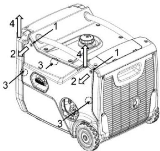
text_image
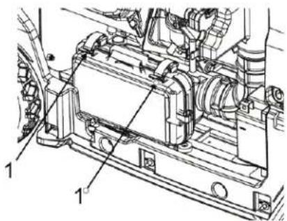
Technical diagram of a portable gas generator with numbered components for identification- Carefully place the generator on wooden blocks to allow an oil drain container to be placed underneath the rubber grommet (5).
- Remove the rubber grommet (5).
- Unscrew the oil drain plug (6) and drain all the engine oil into the container.
- Replace the oil drain plug and rubber grommet.
- Clean up any excess oil.
- REFILL the oil, using the funnel (supplied) and check the oil level. Refer to Engine Oil Level – Check.
- Install and tighten the oil level gauge.
- Reattach the side panel in reverse order to removal.
- Dispose of the used oil properly.
- Start the engine for a brief period and check for leaks.
- Stop the engine and check the oil level. Add oil if level indicates it is needed. Refer to Engine Oil Level – Check.
INSPECT/ADJUST ENGINE VALVE LASH
Only qualified service personnel should perform this maintenance procedure. Contact your local service center to schedule this maintenance.
REPLACE FUEL LINE
Only qualified service personnel should perform this maintenance procedure. Contact your local service center to schedule this maintenance.
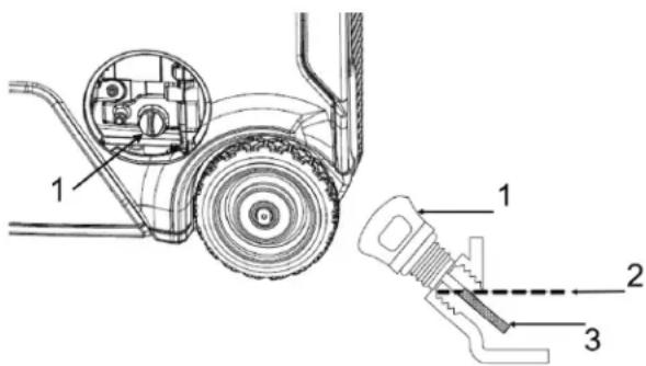
CLEAN FUEL TANK CAP AND STRAINER
Wipe off the fuel cap (1) and surrounding area before removing the fuel cap. Wiping off the fuel cap and surrounding area before removing the fuel cap helps to reduce the amount of contaminants allowed into the fuel system. If there is a build-up of debris in the fuel strainer (2), remove the strainer and rinse out the strainer. Allow the strainer to dry before installing the strainer.
SPARK ARRESTOR
This unit has a spark arrestor fitted to the exhaust outlet of the muffler. The spark arrestor should be cleaned with a soft wire brush after every 50 hours or 3 months of use. The spark arrestor should be replaced after every 100 hours of operation or if it becomes damaged.

WARNING: HOT PARTS OR HOT COMPONENTS CAN CAUSE BURNS OR PERSONAL INJURY. DO NOT ALLOW HOT PARTS OR COMPONENTS TO CONTACT YOUR SKIN. USE PROTECTIVE CLOTHING OR PROTECTIVE EQUIPMENT TO PROTECT YOUR SKIN.
DO NOT PERFORM THIS MAINTENANCE PROCEDURE UNTIL THE MUFFLER HAS COOLED.
text_image
Technical diagram of a mechanical assembly with numbered components labeled 5 and 6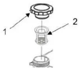
text_image
1 2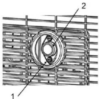
text_image
Technical diagram showing a mechanical component with labeled parts 1 and 2, likely for assembly or maintenance instructions.Remove screws (1). Remove spark arrestor (2) Check the spark arrestor. Carefully clean the spark arrestor with a soft wire brush. If the spark arrestor is damaged, replace the spark arrestor.
To install the spark arrestor, align the mounting holes in the spark arrestor with the mounting holes on the muffler. Insert screws (1) and tighten securely.
SPARK PLUG
Refer to the Specifications section of this manual to determine the proper spark plug part number and spark plug gap for your product.
- DO NOT perform this maintenance procedure with the engine running.
- Turn the generator switch to the off "O" position.
- Remove the side panel as per the Air Filter - Check procedure.
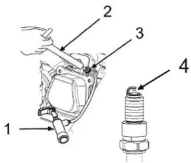
- Remove the spark plug boot (1) by pulling it off the top of the spark plug.
- Use the plug wrench (2) or a spark plug socket to remove the spark plug (3).
- Visually check the spark plug to see if it is damaged. If the insulator is cracked, replace the spark plug. If the electrode is damaged, replace the spark plug.
- Measure the plug gap (4) with a feeler gauge. Adjust the gap as necessary by carefully bending the electrode. Refer to Specifications for the correct gap for your product.
- Install the spark plug by hand and then tighten to 9 ± 2 lb ft ( 12.5 ± 2 Nm). DO NOT overtighten as this may damage the engine.
- Re-attach the spark plug boot and side panel.
INSPECT/REPLACE BATTERY
If the battery voltage is below 12.8 volts, charge the battery. Recommended maximum continuous charge voltage is 15 volts.
If the battery is unable to turn over the engine, even after charging, check the battery terminals are secure and free from corrosion.
If the battery requires replacement:
- Disconnect the negative (-) cable first.
- Disconnect the positive (+) cable second.
To install the new battery:
-
Connect the positive (+) cable first.
-
Connect the negative (-) cable second.
NOTE: Use only genuine parts.

CAUTION - DANGER OF EXPLOSION IF BATTERY IS INCORRECTLY REPLACED, REPLACE ONLY WITH THE SAME OR EQUIVALENT TYPE.
The used battery should be recycled in accordance with local laws.
text_image
Technical diagram showing labeled components of a mechanical assembly, including a spark plug and internal components.STORAGE
PREPARATION FOR STORAGE
When a generator is in storage, air may condense and moisture may appear on the windings. In order to minimize condensation, always store the generator in a dry area. Cover the generator with a protective cover that extends to the ground. The cover should remain loose around the generator in order to allow proper ventilation.
The generator must not be stored in ambient temperatures greater than 131^ F ( 55^ C) as this can damage the CO Detector.
Wait until the generator has cooled before covering it. NEVER operate the generator with the cover installed. It could ignite and cause damage.
STORAGE FOR 1 TO 3 MONTHS
Remove any dirt, rust, grease, and oil from the generator. DO NOT use a pressure washer to clean the generator. Inspect the exterior. Make any necessary repairs.
Add fuel stabilizer to the fuel tank to prevent the gasoline from going bad. Start and run the engine for 5 minutes to ensure that the fuel stabilizer has been pulled in to the carburetor. Shut off the engine and allow the engine to cool.
Turn the generator switch to the off "O" position.
Move the generator to the storage place.
Cover the generator.
STORAGE FOR MORE THAN 3 MONTHS
Remove any dirt, rust, grease, and oil from the generator. DO NOT use a pressure washer to clean the generator. Inspect the exterior. Make any necessary repairs.

WARNING: GASOLINE IS EXTREMELY FLAMMABLE AND IS EXPLOSIVE UNDER CERTAIN CONDITIONS. DRAIN THE FUEL IN A WELL-VENTILATED AREA WITH THE ENGINE STOPPED AND COOL. NEVER SMOKE OR ALLOW FLAMES OR SPARKS IN THE AREA DURING THIS PROCEDURE.
Remove the fuel cap and carefully turn the generator over to pour the gasoline into an appropriate container. Reinstall the fuel cap and start and run the engine until the engine stops, to allow the fuel to drain from the fuel lines, carburetor, and engine system.
Change the engine oil. Refer to Change Engine Oil.
Remove the spark plug and pour a small amount of oil into the cylinder. Install the spark plug but do not install the spark plug boot.
Turn the generator switch to the off "O" position.
Move the generator to the storage place.
Attach the trickle charger to the port on the control panel and to standard AC power to keep the generator battery fully powered for easy start after storage. Disconnect the battery charger once the battery is fully charged (indicated by a green light on the charger)
Cover the generator.
| Symptom Problem | Solution | |
| Engine Will Not Start | Generator switch in the off “0” position Turn the generator switch to the correct position. | |
| Generator inclined Move generator to a levelposition. | ||
| No fuel Fill the fuel tank. | ||
| Bad or contaminated fuel Check the fuel | ||
| Not enough oil in the engine Check the oil level. If low, add the recommended oil. | ||
| Dirty air filter Clean the air filter. | ||
| No spark Replace the spark plug. | ||
| For electric start, start the engine using the recoil starter. | If the generator starts, check the battery voltage on the LCD disaplay. If the battery is providing less than 12.4 volts, charge the battery. | |
| Oil in the combustion chamber Remove spark plug, turn generator switch to off “O” position, pull recoil starter four times to remove oil from combustion chamber. | ||
| If the engine still will not start: Take the unit to an authorized service provider. | ||
| Engine Runs Rough (no load) | Dirty air filter Stop the engine and check the air filter. Clean if needed. | |
| Generator inclined Move generator to a level position. | ||
| If the engine still runs rough: | Take the unit to an authorized service provider. | |
| Engine Shuts Down | Out of fuel | Check the fuel. Fill the tank if necessary. |
| Not enough oil in the engine Check the oil level. If low, add the recommended oil. | ||
| Dirty air filter Clean the air filter. | ||
| Shut off due to CO accumulation & flashing red indicator | Follow all safety instructions on CO Action Label | |
| Generator overloaded | Unplug some of the devices. | |
| Shut off due to CO shutdown system fault & constant yellow indicator | System fault or end of life indication. | |
| If the engine still shuts down: | Take the unit to an authorized service provider. | |
| Engine Runs Rough (with load) | Dirty air filter Stop the engine and check the air filter. Clean if needed. | |
| Generator overloaded | Unplug some of the devices. | |
| Defective device plugged in | Unplug defective device. | |
| If the engine still runs rough: | Take the unit to an authorized service provider. | |
| Engine Runs, But Generator Does Not Provide Power | Generator overloaded, overload light is on | Turn off and unplug all electrical devices, shut down the engine, wait 10 minutes and start the engine, connect fewer or lighter electrical loads. |
| Bad connection | Stop the engine and check the connections. | |
| Defective power cord | Replace the cord. | |
| Defective device plugged in | Unplug defective device. | |
| If there is still no power: | Take the unit to an authorized service provider. | |
SPECIFICATIONS
SPECIFICATIONS
Engine Type ....Single Cylinder, 4-Stroke, Forced Air Cooling
Displacement (cc) 224
Ignition System ......Electronic
Spark Plug Gap .028 - .032 inches (0.7 - 0.8mm)
Fuel Volume 2.1 U.S. gallon (8L)
Fuel Consumption (g/(kW·h) .... ≤ 395
100% load continuous running time (hr) 4.5
50% load continuous running time (hr) 8
Oil Capacity 0.56 quart (0.53L)
Rated Output (DC) 12V 8.3A
Rated Frequency (Hz) 60
Rated Voltage (V) 120
Rated Output Power (kW) 3.5
Surge Output Power (kW) 4.0
Phase .......Single
Total Harmonic Distortion ....../< 3%
RECORD SERIAL NUMBER
Write you model number, machine serial number (see serial number tag in illustration) and date of purchase in the spaces provided below. Your dealer needs this information when ordering parts.
Model No.
Machine Serial No.
Date of Purchase
(To be filled in by purchaser)
For use in a weather protected area only?
Mi-T-M warrants all parts, (except those referred to below), of your new generator to be free from defects in materials and workmanship during the following periods:
For One (1) Years from the date of original purchase.
Defective parts not subject to normal wear and tear will be repaired or replaced at our option during the warranty period. In any event, reimbursement is limited to the purchase price paid.
EXCLUSIONS
- Engine/Motor and Generator are covered under separate warranty by its respective manufacturer and is subject to the terms set forth therein.
- This warranty does not cover parts damaged due to normal wear, misapplication, misuse, operation at other than recommended. Failure to follow recommended operating and maintenance procedures also voids warranty.
- The use of other than genuine manufacturer repair parts will void warranty.
- Parts returned, prepaid to our factory or to an Authorized Mi-T-M Service Center will be inspected and replaced free of charge if found to be defective and subject to warranty. There are no warranties which extend beyond the description of the face hereof. Under no circumstances shall the manufacturer bear any responsibility for loss of use of the unit, loss of time or rental, inconvenience, commercial loss or consequential damages.
For Service or Warranty Consideration, contact Mi-T-M® Corporation, 50 Mi-T-M Drive, Peosta, IA 52068 563-556-7484 / 800-553-9053 / Fax 563-556-1235 Monday - Friday 8:00 a.m. - 5:00 p.m. CST
EXHAUST AND EVAPORATIVE EMISSIONS CONTROL WARRANTY STATEMENT YOUR WARRANTY RIGHTS AND OBLIGATIONS
The California Air Resources Board, the United States Environmental Protection Agency (EPA) and Mi-T-M are pleased to explain the emission control system's warranty on your 2022/2023 small off-road engine/equipment (SORE). In California, new equipment that use small off-road engines must be designed, built and equipped to meet the State's stringent anti-smog standards. Mi-T-M must warrant the exhaust and evaporative emissions control system (E & EECS) on your SOREs for the period listed below provided there has been no abuse, neglect or improper maintenance of your equipment leading to the failure of the evaporative emission control system.
Your E & EECS may include parts such as the carburetor, fuel tanks, fuel lines (for liquid fuel and fuel vapors), fuel caps, valves, canisters, filters, clamps, connectors, and other associated components. Where warrantable conditions exist, Mi-T-M will repair your small off-road engine at no cost to you including diagnosis, parts and labor.
MANUFACTURER'S WARRANTY COVERAGE:
This E & EECS is warranted for two years. If any evaporative emissions-related part on your small off-road engine/equipment is defective, the part will be repaired or replaced by Mi-T-M. OWNER'S WARRANTY RESPONSIBILITIES:
-As the SORE owner, you are responsible for performance of the required maintenance listed in your owner's manual. Mi-T-M recommends that you retain all receipts covering maintenance on your SORE, but Mi-T-M cannot deny warranty coverage solely for the lack of receipts.
-As the SORE owner, you should be aware that Mi-T-M may deny you warranty coverage if your SORE or a part has failed due to abuse, neglect, or improper maintenance or unapproved modifications.
-You are responsible for presenting your SORE to distribution center or service center authorized by Mi-T-M Corporation, 50 Mi-T-M Drive, Peosta, IA 52068 (herein Mi-T-M) as soon as the problem exists. The warranty repairs shall be completed in a reasonable amount of time, not to exceed 30 days.
If you have a question regarding your warranty coverage, you should contact Mi-T-M Customer Service Department at 1-800-553-9053 or by emailing us at corp@mitm.com.
GENERAL EMISSIONS WARRANTY COVERAGE
MI-T-M WARRANTS TO THE ULTIMATE PURCHASER AND EACH SUBSEQUENT PURCHASER THAT THE SORE (1) HAS BEEN DESIGNED, BUILT AND EQUIPPED SO AS TO CONFORM WITH ALL APPLICABLE REGULATIONS; AND (2) IS FREE FROM DEFECTS IN MATERIALS AND WORKMANSHIP THAT CAUSE THE FAILURE OF A WARRANTED PART TO CONFORM WITH THOSE REGULATIONS AS MAY BE APPLICABLE TO THE TERMS AND CONDITIONS STATED BELOW.
(a) The warranty period begins on the date the engine is delivered to an ultimate purchaser or first placed into service. The warranty period is two years.
(b) Subject to certain conditions and exclusions as stated below, the warranty on emissions related parts is as follows:
(1) Any warranted part that is not scheduled for replacement as required maintenance in your owner's manual is warranted for the warranty period stated above. If the part fails during the period of warranty coverage, the part will be repaired or replaced by Mi-T-M according to subsection (4) below. Any such part repaired or replaced under warranty will be warranted for the remainder of the period.
(2) Any warranted part that is scheduled only for regular inspection in your owner's manual is warranted for the warranty period stated above. Any such part repaired or replaced under warranty will be warranted for the remaining warranty period.
(3) Any warranted part that is scheduled for replacement as required maintenance in your owner's manual is warranted for the period of time before the first scheduled replacement date for that part. If the part fails before the first scheduled replacement, the part will be repaired or replaced by Mi-T-M according to subsection (4) below. Any such part repaired or replaced under warranty will be warranted for the remainder of the period prior to the first scheduled replacement point for the part.
(4) Repair or replacement of any warranted part under the warranty provisions herein must be performed at a warranty station at no charge to the owner.
(5) Not withstanding the provisions herein, warranty services or repair will be provided at all of our distribution centers that are franchised to service the subject engines.
(6) The owner must not be charged for diagnostic labor that leads to the determination that a warranted part is in fact defective, provided that such diagnostic work is performed at a warranty station.
(7) Throughout the engine warranty period stated above, Mi-T-M will maintain a supply of warranted parts sufficient to meet the expected demand for such parts.
(8) Any replacement parts that do not increase the exhaust or evaporative emissions of the engine or evaporative emission control system must be used in the performance of any warranty maintenance or repairs and must be provided without charge to the owner. Such use will not reduce the warranty obligations of Mi-T-M.
(9) Add-on or modified parts that are not exempted by the Air Resources Board may not be used. The use of any non-exempted add-on or modified parts by the ultimate purchaser will be grounds for disallowing a warranty claims. Mi-T-M will not be liable to warrant failures of warranted parts caused by the use of a non-exempted add-on or modified part.
(10) Mi-T-M shall provide any documents that describe that Mi-T-M warranty procedures or policies within five working days of request by the Executive Officer.
(c) WARRANTED PARTS:
The repair or replacement of any warranted part otherwise eligible for warranty coverage may be excluded from such warranty coverage if Mi-T-M demonstrates that the engine has been abused, neglected, or improperly maintained, and that such abuse, neglect, or improper maintenance was the direct cause of the need for repair or replacement of the part. That notwithstanding, any adjustment of a component that has a factory installed, and properly operating, adjustment limiting device is still eligible for warranty coverage. The following emissions warranty parts list are covered.
(1) Fuel Tank*
(2) Fuel Cap
(3) Fuel Lines (for liquid fuel and fuel vapors)
(4) Fuel Line Fittings
(5) Clamps*
(6) Pressure Relief Valves*
(7) Control Valves*
(8) Control Solenoids*
(9) Electronic Controls*
(10) Vacuum Control Diaphragms*
(11) Control Cables*
(12) Control Linkages*
(13) Purge Valves*
(14) Gaskets*
(15) Liquid/Vapor Separator
(16) Carbon Canister
(17) Canister Mounting Brackets
(18) Carburetor Purge Port Connector
* Note: As they relate to the evaporative emission control system.
(1) Fuel Metering System
(i) Carburetor and internal parts (and/or pressure regulator or fuel injection system).
(ii) Air/fuel ratio feedback and control system.
(iii) Cold start enrichment system.
(2) Air Induction System
(i) Controlled hot air intake system.
(ii) Intake manifold.
(iii) Air filter.
(3) Ignition System
(i) Spark Plugs.
(ii) Magneto or electronic ignition system.
(iii) Spark advance/retard system.
(4) Exhaust Gas Recirculation (EGR) System
(i) EGR valve body, and carburetor spacer if applicable.
(ii) EGR rate feedback and control system.
(5) Air Injection System
(i) Air pump or pulse valve.
(ii) Valves affecting distribution of flow.
(iii) Distribution manifold.
(6) Catalyst or Thermal Reactor System
(i) Catalytic converter.
(ii) Thermal reactor.
(iii) Exhaust manifold.
(7) Particulate Controls
(i) Traps, filters, precipitators, and any other device used to capture particulate emissions.
(8) Miscellaneous Items Used in Above Systems
(i) Electronic controls.
(ii) Vacuum, temperature, and time sensitive valves and switches.
(iii) Hoses, belts, connectors, and assemblies.
INTRODUCTION
natural_image
Black triangular warning symbol with exclamation mark (no text or numbers)COMPRENDRE LES MOTS D'ALERTE
text_image
AWARNING WARNING CAUTION WMIC. 41 Wash. J.C. Wash. J.N. Tc. M. R.A.R. 03:00 to 06:5 03:00 to 06:5 03:00 to 06:5 03:00 to 06:5 03:00 to 06:5 03:00 to 06:5 03:00 to 06:5 03:00 to 06:5 03:00 to 06:5 03:12 to 06:5 03:12 to 06:5 03:12 to 06:5 03:12 to 06:5 03:12 to 06:5 03:12 to 06:5 03:12 to 06:5 03:12 to 06:5 03:12 to 07:5 03:12 to 07:5 03:12 to 07:5 03:12 to 07:5 03:12 to 07:5 03:12 to 07:5 03:12 to 07:5 03:12 to 07:5 03:12 to 08:5 03:12 to 08:5 03:12 to 08:5 03:12 to 08:5 03:12 to 08:5 03:12 to 08:5 03:12 to 08:5 03:12 to 09:5 03:12 to 09:5 03:12 to 09:5 03:12 to 10:5 03:12 to 10:5 03:12 to 10:5 03:12 to 11:5 03:12 to 11:5 03:12 to 11:5 03:12 to 12:5 03:12 to 12:5 03:12 to 12:5 03:12 to 13:5 03:12 to 13:5 03:12 to 14:5 03:12 to 14:5 03:12 to 15:5 03:12 to 16:5 03:12 to 17:5 03:12 to 18:5 03:12 to 19:5 03:12 to 20:5 03:12 to 21:5 03:12 to 22:5 03:12 to 23:5 03:12 to 24:5 03:12 to 25:5 03:12 to 26:5 03:12 to 27:5 03:12 to 28:5 03:12 to 29:5 03:12 to 30:5 03:12 to 31:5 03:12 to 32:5 03:12 to 33:5 03:12 to 34:5 03:12 to 35:5 03:12 to 36:5 03:12 to 37:5 03:12 to 38:5 03:12 to 39:5 03:12 to 40:5 03:12 to 41:5 03:12 to 42:5 03:12 to 43:5 03:12 to 44:5 03:12 to 45:5 03:12 to 46:5 03:12 to 47:5 03:12 to 48:5 03:12 to 49:5 03:12 to 50:5 03:12 to 51:5 03:12 to 52:5 03:12 to 53:5 03:12 to 54:5 03:12 to 55:5 03:12 to 56:5 03:12 to 57:5 03:12 to 58:5 03:12 to 59:5 03:12 to 60:5 03:12 to 61:5 03:12 to 62:5 03:12 to 63:5 03:12 to 64: ACAUTIONOXYDE DE CARBONE - GAZ TOXIQUE
natural_image
Abstract black-and-white graphic of a bird perched on a human figure with a circular object, set against a dotted background (no text or symbols)⚠️DANGERDANGERPELIGRO
Using a generator indoors CAN KILL YOU IN MINUTES. Generator exhaust contains carbon monoxide. This is a poison you cannot see or smell.
text_image
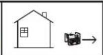
Diagram showing two house configurations with no fire icons, one with a car and another with a truck, next to a vehicle diagram.NEVER use inside a home or garage, EVEN IF doors and windows are open. Only use OUTSIDE and far away from windows, doors, and vents.
text_image
Safety warning symbol showing a person using a fuel pump with a no-smoking sign, next to a warning sign and explosion hazard.BATTERIE
natural_image
Black-and-white icon of a hand with a lightning bolt and smoke trail, symbolizing electrical hazard (no text or symbols)RISQUES ÉLECTRIQUES

ATTENTION: IL Y A UN CONDUCTEUR PERMANENT ENTRE LA GÉNÉRATRICE (ENROULEMENT DU STATOR) ET LE CADRE.

ATTENTION: NE SERT PAS À COUPER LE COURANT.
text_image
AIA PRING ACAUATIONPORTER DES VÊTEMENTS DE PROTECTION
natural_image
Illustration of a person in protective gear with corresponding safety icons (no text or symbols)PRÉPARATION POUR LES URGENCES
natural_image
Illustration of first aid kit, fire extinguisher, and medical first aid box (no text or symbols)INSPECTER LE GROUPE ÉLECTROGÈNE
WARNING: Cancer and Reproductive Harm — www.P65warnings.ca.gov/
SHOCK: A generator is a potential shock hazard which can result in serious injury or death.
- Generator must be kept dry and MUST be grounded before use. See operators manual for
specific instructions.
• Always keep generator three (3) feet from any structure.
EXPLOSIVE FUEL: Gasoline is extremely flammable and its vapors can explode if ignited
causing serious injury or death.
- Do NOT fill fuel tank while engine is hot or running.
ADVERTENCIA
• Always allow for fuel
expansion
- Do not fill while running
Minimum octane rating of 85.
Maximum 10% ethanol.
Gasolina REGULAR SOLAMENTE
FLASHING RED INDICATOR = Automatic Shutoff Event. Leave area immediately and relocate to an open outdoor area. Verifikate area thoroughly before occupying again. Ensure the generator is located in an open outdoor area. MOVE TO FRESH AIR AND GET MEDICAL HELP IF SICK, DIZZY OR WEAK.
CONSTANT YELLOW INDICATOR = System Fault. Contact Dealer

SYSTÈME D'ARRÊT POUR DÉTECTION DE MONOXYDE DE CARBONE EN SERVICE.
Using a generator indoors CAN KILL YOU IN MINUTES. Generator exhaust contains carbon monoxide. This is a poison you cannot see or smell.
NEVER use inside a home
or garage. EVEN IF doors
and windows are open.
Only use OUTSIDE and far
away from windows, doors,
and vents.
DANGER
text_image
Technical diagram of a vehicle's internal components with numbered parts labeled 1 through 11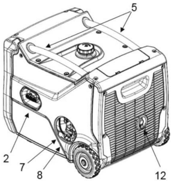
text_image
Technical diagram of a portable gas generator with numbered components labeled 2 through 12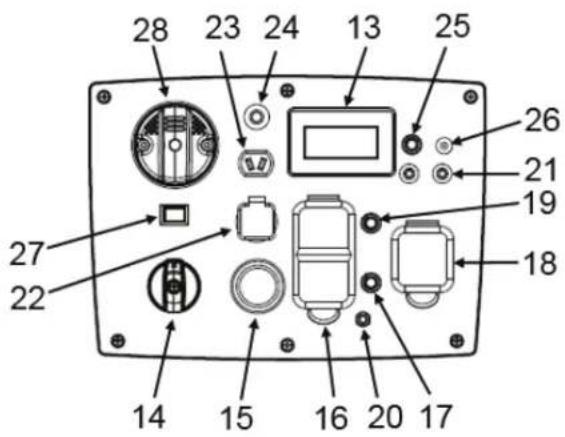
text_image
28 23 24 13 25 26 21 19 18 27 22 14 15 16 20 17text_image
0 ① N ② +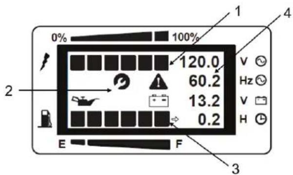
text_image
0% 100% 120.0 60.2 13.2 0.2 E F 2 V Hz V H 3 4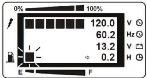
text_image
0% 100% 120.0 60.2 13.2 0.2 E F V ✓ Hz ✓ V ✓ H ✓PRISES PARALLÈLES
text_image
Technical diagram showing labeled components of a mechanical or electrical connector with numbered parts 1 and 2.120 V C.A., 20 A, DDFT DOUBLE
natural_image
Pure electrical circuit lines without any symbolsnatural_image
Line drawing of a portable gas generator with wheels and internal components, no text or symbols present
text_image
Technical diagram of a device rear panel with labeled components and a 4x magnified view showing a red component.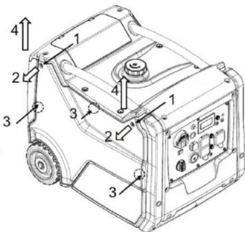
text_image
Technical diagram of a vehicle's internal components with numbered parts and directional arrows indicating assembly or movement.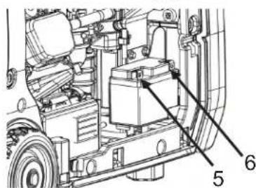
text_image
Technical diagram of a vehicle's internal components with numbered labels pointing to specific parts.RACCORDEMENT À L'ALIMENTATION SECTEUR DOMESTIQUE
natural_image
Black-and-white icon of a hand with a lightning bolt and smoke trail, symbolizing electrical hazard (no text or symbols)text_image
Technical diagram of a lawn mower with labeled parts and mechanical assembly detailstext_image
0% 100% 120.0 60.2 13.2 0.2 E F 1 V Hz V Htext_image
Technical diagram of a vehicle engine assembly with numbered components and labeled parts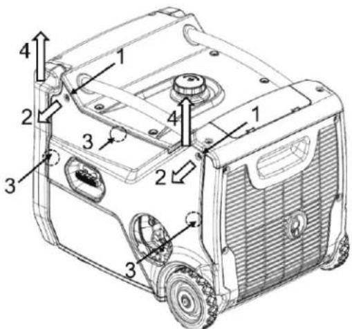
text_image
Technical diagram of a portable gas generator with numbered components for identificationtext_image
Technical diagram of a vehicle engine assembly with numbered components labeled 5 and 6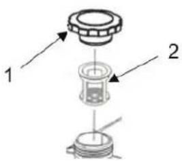
text_image
1 2text_image
Technical diagram of a mechanical component with labeled parts 1 and 2CONDITIONS DE LA GARANTIE
natural_image
Black triangular warning symbol with exclamation mark (no text or numbers)COMPRENDA PALABRAS DE ALERTAS
natural_image
Abstract black-and-white graphic of a bird-like figure with a circular head, set against a dotted cloud background (no text or symbols)Using a generator indoors CAN KILL YOU IN MINUTES. Generator exhaust contains carbon monoxide. This is a poison you cannot see or smell.
text_image
Diagram showing two house scenarios with red circles highlighting fire-related objects, and a vehicle moving to a car.NEVER use inside a home or garage, EVEN IF doors and windows are open.
Only use OUTSIDE and far away from windows, doors, and vents.
natural_image
Black starburst graphic symbol on white background, no text or symbols present
natural_image
Silhouette of a person refueling a fuel pump with a no-smoking symbol (no text or labels)RIESGOS DE ELECTRICOS

HAY UN CONDUCTOR PERMANENTE ENTRE EL GENERADOR (BOBINADO DEL ESTATOR) Y EL MARCO.

PRECAUCION: NO INTERRUMPA LA CORRIENTE.
natural_image
Black-and-white illustration of a hand with a lightning bolt and smoke trail, symbolizing electrical hazard (no text or symbols)natural_image
Silhouette of a person wearing various safety gear and clothing items (no text or symbols)natural_image
Illustration of first aid kit, fire extinguisher, and medical kit with cross symbol (no text or labels)WARNING: Cancer and Reproductive Harm — www.P65warnings.ca.gov/
SHOCK: A generator is a potential shock hazard which can result in serious injury or death. Generator must be kept dry and MUST be grounded before use. See operators manual for specific instructions.
• Always keep generator three (3) feet from any structure.
EXPLOSIVE FUEL: Gasoline is extremely flammable and its vapors can explode if ignited causing serious injury or death.
- Do NOT fill fuel tank while engine is hot or running.
ADVERTENCIA
• Always allow for fuel expansion
- Do not fill while running
Add fresh, unleaded fuel and stabilizer
FLASHING RED INDICATOR = Automatic Shutoff Event. Leave area immediately and relocate to an open outdoor area. Ventilate area thoroughly before occupying again. Ensure the generator is located in an open outdoor area. MOVE TO FRESH AIR AND GET MEDICAL HELP IF SICK, DIZZY OR WEAK
CONSTANT YELLOW INDICATOR = System Fault. Contact Dealer.

SYSTÈME D'ARRÊT POUR DÉTECTION DE MONOXYDE DE CARBONE EN SERVICE.
Using a generator indoors CAN KILL YOU IN MINUTES. Generator exhaust contains carbon monoxide. This is a poison you cannot see or smell.
NEVER use inside a home or garage, EVEN IF doors and windows are open.
Only use OUTSIDE and far away from windows, doors, and vents.
DANGER
text_image
Technical diagram of a portable gas stove with numbered components for identification
text_image
Technical diagram of a portable gas generator with numbered components labeled 2 through 12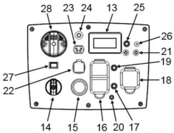
text_image
28 23 24 13 25 26 21 19 18 27 22 14 15 16 20 17text_image
0% 100% 120.0 60.2 13.2 0.2 E F 2 V Hz V H 3 4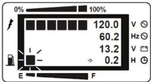
text_image
0% 100% 120.0 60.2 13.2 0.2 E F V √ Hz √ V √ H √ENTRADAS PARALELAS
text_image
Technical diagram showing labeled components of a mechanical or electrical component with numbered parts 1 and 2.natural_image
Pure electrical circuit lines without any symbolsnatural_image
Line drawing of a portable gas generator with wheels and internal components, no text or symbols present
text_image
1 2 4x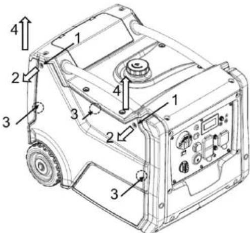
text_image
Technical diagram of a portable industrial machine with numbered components and directional arrows indicating assembly or movement.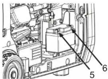
text_image
Technical diagram of a vehicle's internal components with numbered labels pointing to specific parts.natural_image
Black-and-white icon of a hand with a lightning bolt and smoke trail, symbolizing electrical hazard (no text or symbols)text_image
Technical diagram of a lawn mower with labeled parts and a close-up view showing tool path and alignment.text_image
Technical diagram of a mechanical assembly with numbered components, likely for engineering or manufacturing documentation.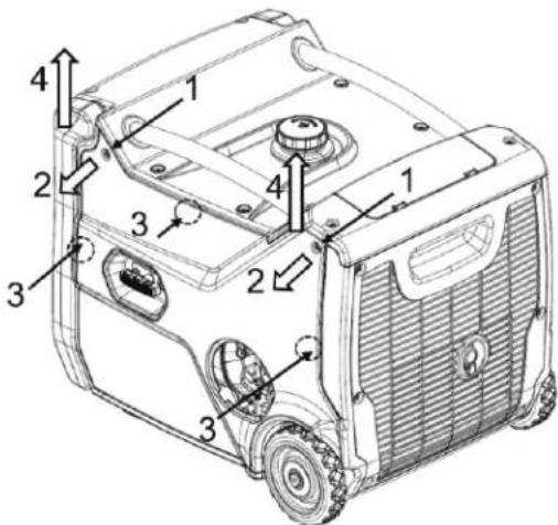
text_image
Technical diagram of a portable electric vehicle with numbered components for identificationtext_image
Technical diagram of a mechanical assembly with numbered components labeled 5 and 6
text_image
Diagram showing a mechanical assembly with labeled parts 1 and 2, likely illustrating a component or assembly step.text_image
Technical diagram of a mechanical component with labeled parts 1 and 2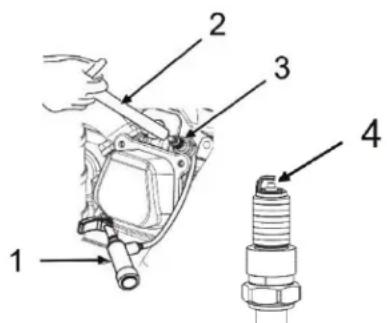
text_image
Technical diagram showing labeled components of a mechanical assembly, including a spark plug and internal components.Date of manufacture / Date de fabrication: 2021-1 2 3 4 5 6 7 8 9 10 11 12
For use in a weather protected area only?
Lunes - Viernes 8:00 a.m. - 5:00 p.m. CST
Manufactured by Mi-T-M
50 Mi-T-M Drive, Peosta IA 52068
563-556-7484/ Fax 563-556-1235