GEN3500iMM1 - Generator Mi-T-M - Free user manual and instructions
Find the device manual for free GEN3500iMM1 Mi-T-M in PDF.

User questions about GEN3500iMM1 Mi-T-M
0 question about this device. Answer the ones you know or ask your own.
Ask a new question about this device
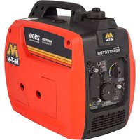
Download the instructions for your Generator in PDF format for free! Find your manual GEN3500iMM1 - Mi-T-M and take your electronic device back in hand. On this page are published all the documents necessary for the use of your device. GEN3500iMM1 by Mi-T-M.
USER MANUAL GEN3500iMM1 Mi-T-M
natural_image
Abstract geometric logo design resembling the letter 'M' in stylized letters (no text or symbols)Mi-T-M®
CORPORATION
THANK YOU for purchasing a Mi-T-M product.
READ THIS MANUAL carefully to learn how to operate and service your machine correctly. Failure to do so could result in personal injury or equipment damage.
THIS MANUAL SHOULD BE CONSIDERED a permanent part of your machine and should remain with the machine when you sell it.
MEASUREMENTS in this manual are given in both metric and customary U.S. unit equivalents. Use only correct replacement parts and fasteners. Metric and inch fasteners may require a specific metric or inch wrench.
RIGHT HAND AND LEFT HAND sides are determined by facing the control panel end of the machine.
The SERIAL NUMBER is located in the Specification or Identification Numbers section. Accurately record all the numbers to help in tracing the machine should it be stolen. Your dealer also needs these numbers when you order parts. File the identification numbers in a secure place off the machine.
WARRANTY is provided from your dealer for customers who operate and maintain their equipment as described in this manual. The warranty is explained on the warranty certificate shown in this manual.
This warranty provides you the assurance that your dealer will back products where defects appear within the warranty period. Should the equipment be abused, or modified to change its performance beyond the original factory specifications, the warranty will become void.
THIS SPARK IGNITION SYSTEM COMPLIES WITH CANADIAN ICES-002. CE SYSTÈME D'ALLUMAGE PAR ÊTINCELLE EST CONFORME À LA NORME NMB-002 DU CANADA.
⚠ WARNING
⚠ WARNING: This product can expose you to chemicals including Lead, which is known to the State of California to cause cancer and birth defects or other reproductive harm. For more information go to www.P65Warnings.ca.gov
WARNING
⚠ WARNING: This product can expose you to chemicals including carbon monoxide, which is known to the State of California to cause birth defects or other reproductive harm. For more information go to www.P65Warnings.ca.gov
NOTICE
FEDERAL EMISSION COMPONENT DEFECT WARRANTY and CALIFORNIA EMISSION CONTROL WARRANTY are applicable to only those engines / generators complied with EPA (Environmental Protection Agency) and CARB (California Air Resources Board) emission regulations in the U.S.A.
NOTICE
To the engines / generators exported to and used in the countries other than the U.S.A., warranty service shall be performed by the distributor in each country in accordance with the standard Mi-T-M engine / generator warranty policy as applicable.
AIR INDEX
To show compliance with California emission regulations, a hang tag has been provided displaying the Air Index level and durability period of this engine.
The Air Index level defines how clean an engine's exhaust is over a period of time. A bar graph scaled from “0” (most clean) to “10” (least clean) is used to show an engine's Air Index level. A lower Air Index level represents cleaner exhaust from an engine.
The period of time (in hours) that the Air Index level is measured is known as the durability period. Depending on the size of the engine, a selection of time periods can be used to measure the Air Index level (see below).
Descriptive Term Applicable to Emissions Durability Period
Moderate: 50 hours (engine from 0 to 80 cc)
125 hours (engine greater than 80 cc)
Intermediate: 125 hours (engine from 0 to 80 cc)
250 hours (engine greater than 80 cc)
Extended: 300 hours (engine from 0 to 80 cc)
500 hours (engine greater than 80 cc)
Notice: This hang tag must remain on the engine or piece of equipment, and only be removed by the ultimate purchaser before operation.
CONTENTS
INTRODUCTION....2
CONTENTS....4
SAFETY 5
CONTROLS 13
PREPARING THE GENERATOR....16
OPERATION....20
SERVICE....21
STORAGE 25
TROUBLESHOOTING....26
SPECIFICATIONS 27
ALL INFORMATION, ILLUSTRATIONS AND SPECIFICATIONS IN THIS MANUAL ARE BASED ON THE LATEST INFORMATION AVAILABLE AT THE TIME OF PUBLICATION. THE RIGHT IS RESERVED TO MAKE CHANGES AT ANY TIME WITHOUT NOTICE.
RECOGNIZE SAFETY INFORMATION
This is the safety alert symbol. When you see this symbol on your machine or in this manual, be alert to the potential for personal injury.
Follow recommended precautions and safe operating practices.

natural_image
Black triangular warning symbol with exclamation mark (no text or numbers)UNDERSTAND SIGNAL WORDS
A signal word--DANGER, WARNING or CAUTION--is used with the safety-alert symbol. DANGER identifies the most serious hazards.
DANGER or WARNING safety signs are located near specific hazards. General precautions are listed on CAUTION safety signs. CAUTION also calls attention to safety messages in this manual.
⚠️ DANGER
WARNING
CAUTION
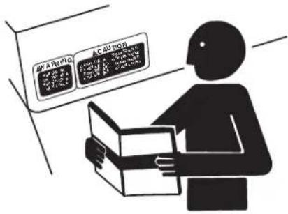
FOLLOW SAFETY INSTRUCTIONS
Carefully read all safety messages in this manual and safety signs on your machine. Keep safety signs in good condition. Replace missing or damaged safety signs. Be sure new equipment components and repair parts include the current safety signs. Replacement safety signs are available from your Mi-T-M Customer Service Representative.
Learn how to operate the machine and how to use controls properly. Do not let anyone operate without instruction.
Keep your machine in proper working condition. Unauthorized modifications to the machine may impair the function and/or safety and affect machine life.
If you do not understand any part of this manual and need assistance, contact your Mi-T-M Customer Service Representative.

CARBON MONOXIDE - POISONOUS GAS
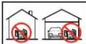
Use generator outdoors, away from open windows, vents, or doors. Keep generator at least 1 meter (3 feet) away from any structure or building during use.
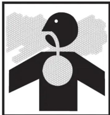
Generator exhaust contains carbon monoxide - a poisonous gas that can kill you. You CAN NOT smell or see this gas.
Never use a generator in enclosed or partially-enclosed spaces. Generators can produce high levels of carbon monoxide very quickly. When you use a portable generator, remember that you cannot smell or see carbon monoxide. Even if you can't smell exhaust fumes, you may still be exposed to carbon monoxide.
If you start to feel sick, dizzy, or weak while using a generator, get to fresh air RIGHT AWAY. DO NOT DELAY. The carbon monoxide from
natural_image
Abstract black-and-white graphic of a bird-like figure with a circular head and loop, set against a pixelated cloud background (no text or symbols)generators can rapidly lead to full incapacitation and death.
If you experience serious symptoms, get medical attention immediately. Inform medical staff that carbon monoxide poisoning is suspected. If you
⚠️ DANGERDANGERPELIGRO
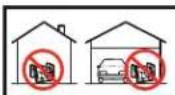
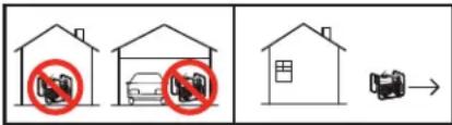
Using a generator indoors CAN KILL YOU IN MINUTES. Generator exhaust contains carbon monoxide. This is a poison you cannot see or smell.
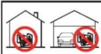
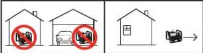
NEVER use inside a home or garage, EVEN IF doors and windows are open.
Only use OUTSIDE and far away from windows, doors, and vents.
experienced symptoms while indoors, have someone call the fire department to determine when it is safe to re-enter the building.
Never operate the generator in an explosive atmosphere, near combustible materials or where ventilation is not sufficient to carry away exhaust fumes. Exhaust fumes can cause serious injury or death.
NEVER use a generator indoors, including in homes, garages, basements, crawl spaces, and other enclosed or partially-enclosed areas, even with ventilation. Opening doors and windows or using fans will not prevent carbon monoxide build-up in the home.
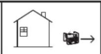
Follow the instructions that come with your generator. Locate the unit outdoors and away from doors, windows, and vents that could allow the carbon monoxide gas to come indoors.
ONLY run generator outdoors and away from air intakes.
NEVER run generator inside homes, garages, sheds, or other semi-enclosed spaces. These spaces can trap poisonous gases EVEN IF you run a fan or open doors and windows.
If you start to feel sick, dizzy, or weak while using the generator, shut if off and get fresh air RIGHT AWAY. See a doctor. You may have carbon monoxide poisoning.
Install battery-operated carbon monoxide alarms or plug-in carbon monoxide alarms with battery back-up in your home, according to the manufacturer's installation instructions. The carbon monoxide alarms should be certified to the requirements of the latest safety standards for carbon monoxide alarms. (UL 2034, IAS 6-96, or CSA 6.19.01).
Test your carbon monoxide alarm frequently and replace dead batteries.
SAFETY WARNING WHEN REFUELING
Gasoline is extremely flammable and its vapors can explode if ignited.
Observe all safety regulations for the safe handling of fuel. Handle fuel in safety containers. If the container does not have a spout, use a funnel.
Do not overfill the fuel tank, leave room for the fuel to expand.
Do not refill fuel tank while the engine is running. Before refueling the generator, turn it off and let it cool down. Gasoline spilled on hot engine parts could ignite.
Fill the tank only on an area of bare ground. While fueling the tank, keep heat, sparks and open flame away. Carefully clean up any spilled fuel before starting engine.
Always fill fuel tank in an area with plenty of ventilation to avoid inhaling dangerous fumes.
NEVER store fuel for your generator in the home. Gasoline, propane, kerosene, and other flammable liquids should be stored outside of living areas in properly-labeled, non-glass safety containers. Do not store them near a fuel-burning appliance, such as a natural gas water heater in a garage. If the fuel is spilled or the container is not sealed properly, invisible vapors from the fuel can travel along the ground and can be ignited by the appliance's pilot light or by arcs from electric switches in the appliance.
natural_image
Abstract black starburst graphic on white background (no text or symbols)
natural_image
Silhouette of a person refueling a fuel pump with a no-smoking symbol (no text or labels)ELECTRICAL HAZARDS
THE GENERATOR (STATOR WINDING) IS ISOLATED FROM THE FRAME AND FROM THE AC RECEPTACLE GROUND PIN.
ELECTRICAL DEVICES REQUIRE A GROUNDED RECEPTACLE PIN CONNECTION WILL NOT FUNCTION IF THE RECEPTACLE GROUND PIN IS NOT FUNCTIONAL.
CAUTION: NOT FOR INTERRUPTING CURRENT.
This product must be grounded. If it should malfunction or breakdown, grounding provides a path of least resistance for electric current to reduce the risk of electric shock.
DANGER - IMPROPER CONNECTION OF THE EQUIPMENT-GROUNDING CONDUCTOR CAN RESULT IN A RISK OF ELECTROCUTION. CHECK WITH A QUALIFIED ELECTRICIAN OR SERVICE PERSON IF YOU ARE INDOUBT AS TO WHETHER THE UNIT IS PROPERLY GROUNDED.
This generator is equipped with a grounding terminal for your protection. Always complete the ground path from the generator to an external ground source as instructed in the section labeled "Grounding Instructions" in the Preparation section of this manual.
The generator is a potential source of electrical shock if not kept dry. Keep the generator dry and do not use in rain or wet conditions. To protect from moisture, operate it on a dry surface under an open, canopy-like structure. Dry your hands if wet before touching the generator.
Plug appliances directly into the generator. Or, use a heavy duty, outdoor-rated extension cord that is rated (in watts or amps) at least equal to the sum of the connected appliance loads. Check that the entire cord is free of cuts or tears and that the plug has all three prongs, especially a grounding pin.
NEVER try to power the house wiring by plugging the generator into a wall outlet, a practice known as "back feeding". This is an extremely dangerous practice that presents an electrocution risk to utility workers and neighbors served by the same utility transformer. It also bypasses some of the built-in household circuit protection devices.
If you must connect the generator to the house wiring to power appliances, have a qualified electrician install the appropriate equipment in accordance with local electrical codes. Or, check with your utility company to see if it can install an appropriate power transfer switch.
For power outages, permanently installed stationary generators are better suited for providing backup power to the home. Even a properly connected portable generator can become overloaded. This may result in overheating or stressing the generator components, possibly leading to a generator failure.
natural_image
Black-and-white illustration of a hand with a lightning bolt and smoke trail, symbolizing electrical hazard (no text or symbols)IMPORTANT SAFETY INSTRUCTIONS

WARNING: TO REDUCE THE RISK OF INJURY, READ THIS OPERATOR'S MANUAL COMPLETELY BEFORE USING. WHEN USING THIS PRODUCT, THE FOLLOWING BASIC PRECAUTIONS SHOULD ALWAYS BE FOLLOWED:
- Read all the instructions before using the product.
-
Do not enclose the generator nor cover it with a box. The generator has a built-in forced air cooling system, and may become overheated if it is enclosed. If generator has been covered to protect if from the weather during non use, be sure to remove it and keep it well away from the area during generator use.
-
Operate the generator on a level surface. It is not necessary to prepare a special foundation for the generator. However, the generator will vibrate on an irregular surface, so choose a level place without surface irregularities.
If the generator is tilted or moved during operation, fuel may spill and/or the generator may tip over, causing a hazardous situation.
Proper lubrication cannot be expected if the generator is operated on a steep incline or slope. In such a case, piston seizure may occur even if the oil is above the upper level.
-
Pay attention to the wiring or extension cords from the generator to the connected device. If the wire is under the generator or in contact with a vibrating part, it may break and possibly cause a fire, generator burnout, or electric shock hazard. Replace damaged or worn cords immediately.
-
Do not operate in rain, in wet or damp conditions, or with wet hands. The operator may suffer severe electric shock if the generator is wet due to rain or snow.
-
If wet, wipe and dry it well before starting. Do not pour water directly over the generator, nor wash it with water.
-
Be extremely careful that all necessary electrical grounding procedures are followed during each and every use. Failure to do so can be fatal.
-
NEVER try to power the house wiring by plugging the generator into a wall outlet, a practice known as "back feeding". This is an extremely dangerous practice that presents an electrocution risk to utility workers and neighbors served by the same utility transformer. It also bypasses some of the built-in household circuit protection devices.
If you must connect the generator to the house wiring to power appliances, have a qualified electrician install the appropriate equipment in accordance with local electrical codes. Or, check with your utility company to see if it can install an appropriate power transfer switch.
- No smoking while charging a battery. The battery emits flammable hydrogen gas, which can explode if exposed to electric arcing or open flame. Keep the area well-ventilated and keep open flames / sparks away when charging a battery.
IMPORTANT SAFETY INSTRUCTIONS
- Engine becomes extremely hot during and for some time after operation. Keep combustible materials well away from generator area. Be very careful not to touch any parts of the hot engine especially the muffler area or serious burns may result.
- Keep children and all bystanders at a safe distance from work area.
- It is absolutely essential that you know the safe and proper use of the power tool or appliance that you intend to use. All operators must read, understand and follow the tool / appliance owners manual. Tool and appliance applications and limitations must be understood. Follow all directions given on labels and warnings. Keep all instruction manuals and literature in a safe place for future reference.
- Use only "LISTED" extension cords. When a tool or appliance is used outdoors, use only extension cords marked "For Outdoor Use". Extension cords, when not in use should be stored in a dry and well ventilated area.
- Always disconnect tools or appliances when not in use, before servicing, adjusting, or installing accessories and attachments.
SAVE THESE INSTRUCTIONS
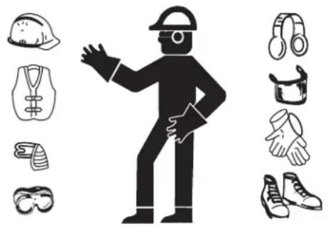
WEAR PROTECTIVE CLOTHING
Wear close fitting clothing and safety equipment appropriate to the job.
Wear a suitable hearing protective device such as ear-muffs or earplugs to protect against objectionable or uncomfortable loud noises.
Operating equipment safely requires the full attention of the operator. Do not wear radio or music headphones while operating machine.
natural_image
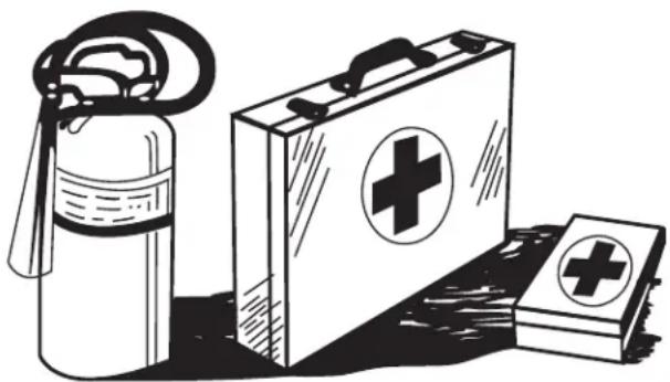
Illustration of a person wearing various safety gear and clothing (no text or symbols)PREPARE FOR EMERGENCIES
Keep a first aid kit and fire extinguisher handy.
Keep emergency numbers for doctors, ambulance service, hospital and fire department near your telephone.
Be prepared if a fire starts.
natural_image
Illustration of a first aid kit, fire extinguisher, and medical kit with cross symbols (no text or labels)INSPECT GENERATOR
Be sure all covers, guards and shields are tight and in place.
Locate all operating controls and safety labels.
Inspect power cord for damage before using. There is a hazard of electrical shock from crushing, cutting or heat damage.
SERVICE GENERATOR SAFELY
Before servicing the generator, disconnect all equipment and allow unit to cool down.
Service generator in a clean dry flat area.
Make sure the engine is stopped before starting any maintenance servicing or repair.
WARNING

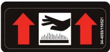
CARBON MONOXIDE DETECTION.
FLASHING RED INDICATOR = Automatic Shutoff Event. Leave area immediately and relocate to an open outdoor area. Ventilate area thoroughly before occupying again. Ensure the generator is located in an open outdoor area. MOVE TO FRESH AIR AND GET MEDICAL HELP IF SICK, DIZZY OR WEAK.
CONSTANT YELLOW INDICATOR = System Fault. Contact Dealer.


34-4055/110521
⚠ AVERTISSEMENT

DÉTECTION DE MONOXYDE DE CARBONE.
Using a generator indoors CAN KILL YOU IN MINUTES. Generator exhaust contains carbon monoxide. This is a poison you cannot see or smell.
NEVER use inside a home or garage, EVEN IF doors and windows are open.
Only use OUTSIDE and far away from windows, doors, and vents.
34-4056
⚠ WARNING
WARNING: Cancer and Reproductive Harm — www.P65warnings.ca.gov/SHOCK: A generator is a potential shock hazard which can result in serious injury or death.
- Generator must be kept dry and MUST be grounded before use. See operators manual for specific instructions.
- Always keep generator three (3) feet from any structure. PLOSIVE FUEL: Gasoline is extremely flammable and its vapors can explode if ignited using serious injury or death.
- Do NOT fill fuel tank while engine is hot or running.
⚠ AVERTISSEMENT/ADVERTENCIA
The safe use of this product requires an understanding of the information on the product and in this operator's manual as well as a knowledge of the project you are attempting. Before use of this product, familiarize yourself with all operating features and safety rules.
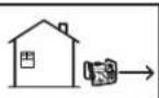
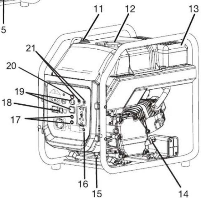
120 V AC RECEPTACLES
Your generator has two single phase, 60 Hz outlets that are 120 Volt AC, 20 Amp receptacles and one 120 Volt AC 30 Amp RV receptacle. These can be used for operating appropriate appliances, electrical lighting, tools, and motor loads.
AC CIRCUIT BREAKER
The circuit breaker is provided to protect the generator against electrical overload. The circuit breaker may be reset by pressing the circuit breaker reset button.
AIR FILTER
The air filter helps to limit the amount of dirt and dust drawn into the unit during operation.
AUTO IDLE SWITCH
The auto idle switch is used to control the speed of the engine and conserve fuel. When the switch is in the ON (I) position and no appliances are connected to the unit, the engine will idle. If an appliance is added, the engine speed will increase to power the item. If the appliance is removed, the engine will return to idle.
CO DETECTOR -AUTOMATIC SHUTOFF
The generator's carbon monoxide sensor is designed to monitor the level of carbon monoxide present during generator operation. If the unit is positioned incorrectly and carbon monoxide levels rise to an unsafe level, the LED on the sensor will flash red and the generator will automatically shut down. Leave the area immediately and relocate to an open outdoor area. Ventilate the area thoroughly before occupying again. Ensure the generator is located in an open, outdoor area and point exhaust away from occupied structures before restarting.
NOTE: After a shutoff event has occurred, the LED will continue to flash red for up to 20 minutes. Once the generator is relocated and CO levels are safe, the generator can be restarted even if the light is still flashing.
FUEL TANK
The fuel tank has a capacity of 3.3 gallons.
GROUND TERMINAL
The ground terminal is used to assist in properly grounding the generator to help protect against electrical shock. Consult with a qualified local electrician for grounding requirements in your area.
LOW OIL SHUT DOWN PROTECTOR
The low oil sensor causes the engine to stop if the level of lubricant in the crankcase is insufficient. The engine may not be restarted until sufficient engine lubricant has been added to the generator.
OIL CAP/DIPSTICK
Remove the oil fill cap to check and add lubricant to the generator when necessary.
OIL DRAIN PLUG
When changing the engine lubricant, unscrew and remove the oil drain plug to allow old engine lubricant to be drained.
RESET BUTTON
The reset button is used to restore power if an overload occurs. To restore power, remove the last electrical load added, then depress the reset button.
RECOIL STARTER
The starter grip and rope is used (along with the engine switch) to start the generator's engine.

WARNING: DO NOT PUT FOREIGN OBJECTS INTO THE PLUG RECEPTACLE.

CAUTION: DO NOT PLUG MORE THAN TWO APPLIANCES INTO THE GENERATOR AT A TIME.

CAUTION: IF CIRCUIT BREAKER CONTINUES TO TRIP, CHECK APPLIANCE FOR DEFECT. IF GENERATOR IS MALFUNCTIONING, SEE YOUR AUTHORIZED MI-T-M SERVICE CENTER.

NEVER INTERFERE WITH THE OPERATION OF THE CIRCUIT BREAKER KNOB OR KEEP PUSHING IT IN THE "ON" POSITION.
GROUNDING INSTRUCTIONS
This product must be grounded. If it should malfunction or breakdown, grounding provides a path of least resistance for electric current to reduce the risk of electric shock.

DANGER - IMPROPER CONNECTION OF THE EQUIPMENT-GROUNDING CONDUCTOR CAN RESULT IN A RISK OF ELECTROCUTION. CHECK WITH A QUALIFIED ELECTRICIAN OR SERVICE PERSON IF YOU ARE IN DOUBT AS TO WHETHER THE UNIT IS PROPERLY GROUNDED.
The ground terminal on the frame must always be used to connect the generator to a suitable ground source. The ground path should be made with #8 size wire. Connect the grounding wire securely to the ground terminal. Connect the other end of the wire securely to a suitable ground source.
The National Electric Code contains several practical ways in which to establish a good ground source. Examples given below illustrate a few of the ways in which a good ground source may be established.
A metal underground water pipe in direct contact with the earth for at least 10 feet can be used as a grounding source. If an pipe is unavailable, an 8 foot length of pipe or rod may be used as the ground source. The pipe should be 3/4 inch trade size or larger and the outer surface must be noncorrosive. If a steel or iron rod is used it should be at least 5/8 inch diameter and if a nonferrous rod is used it should be at least 1/2 inch diameter and be listed as material for grounding. Drive the rod or pipe to a depth of 8 feet. If a rock bottom is encountered less than 4 feet down, bury the rod or pipe in a trench. All electrical tools and appliances operated from this generator, must be properly grounded by use of a third wire or be “Double Insulated”.
It is recommended to:
- Use electrical devices with 3 prong power cords.
- Use an extension cord with a 3 hole receptacle and a 3 prong plug at the opposite ends to ensure continuity of the ground protection from the generator to appliance.
We strongly recommend that all applicable federal, state and local regulations relating to grounding specifications be checked and followed.
APPLICATIONS
This generator is designed to supply electrical power for operating compatible electrical lighting, appliances, tools, and motor loads.
The generator has 2 red carriage brackets fitted underneath the base to prevent damage caused by rough handling during transit.

IMPORTANT- THESE BE MUST BE REMOVED BEFORE USE, OTHERWISE THE UNIT WILL VIBRATE EXCESSIVELY AND DAMAGE MAY OCCUR.

natural_image
Black-and-white icon of a hand with a lightning bolt and smoke trail, symbolizing electrical hazard (no text or symbols)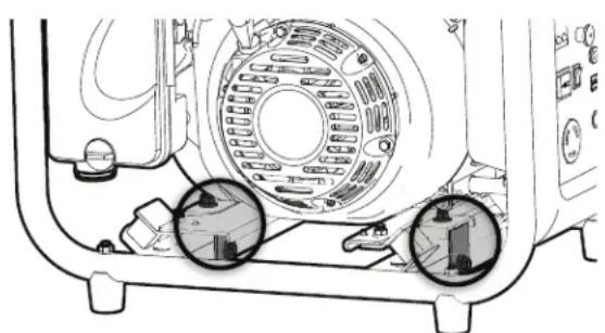
natural_image
Technical line drawing of a mechanical device with circular components and adjustment knobs (no text or symbols)Only use OUTSIDE and at least 20 feet away from windows, doors, and vents as recommended by the U.S Department of Health and Human Services Centers for Disease Control and Prevention. Your specific home and/or wind conditions may require additional distance.
NEVER use inside a home or garage, EVEN IF doors and windows are open.
Always position the generator on a flat firm surface.
There may be General or State Occupational Safety and Health Administration (OSHA) regulations, local codes or ordinances that apply to the intended use of the generator.
Please consult a qualified electrician, electrical inspector, or the local agency having jurisdiction:
- In some areas, generators are required to be registered with local utility companies.
- If the generator is used at a construction site, there may be additional regulations which must be observed.
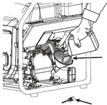
CHECKING/ADDING OIL
NOTICE: Attempting to start the engine before it has been properly filled with oil will result in equipment failure.
NOTE: If a separate engine manual is provided for this product, please follow the instructions provided in the engine manual instead of the information listed below.
Engine lubricant has a major influence on engine performance and service life. For general, all-temperature use, SAE 10W-30 is recommended. Always use a 4-stroke motor lubricant that meets or exceeds the requirements for API service classification SJ.
This engine comes with a feature that will shut off the engine when a specific lubricant level is not maintained. The engine will not restart until an appropriate lubricant level is reached.
NOTE: Non-detergent or 2-stroke engine lubricants will damage the engine and should not be used.
- Unscrew the oil cap/dipstick and remove.
- Wipe dipstick clean and re-seat in hole; do not re-thread.
- Remove dipstick again and check lubricant level. Lubricant level should fall between the minimum and maximum marks on the dipstick.
- If level is low, add engine lubricant until the fluid level rises between the minimum and maximum marks on the dipstick.
- Replace and secure the oil cap/dipstick.

WARNING: WARNING: EXPLOSIVE FUEL! GASOLINE IS EXTREMELY FLAMMABLE AND ITS VAPORS CAN EXPLODE IF IGNITED.
STORE GASOLINE ONLY IN APPROVED CONTAINERS, IN WELL VENTILATED, UNOCCUPIED BUILDINGS AND AWAY FROM SPARKS OR FLAMES.
DO NOT FILL THE FUEL TANK WHILE THE ENGINE
natural_image
Technical diagram of a mechanical assembly with a hand operating a component (no visible text or labels)IS HOT OR RUNNING, SINCE SPILLED FUEL COULD IGNITE IF IT COMES IN CONTACT WITH HOT PARTS OR SPARKS FROM IGNITION. DO NOT START THE ENGINE NEAR SPILLED FUEL.
NEVER USE GASOLINE AS A CLEANING AGENT.

WARNING: DO NOT OVERFILL THE FUEL TANK, LEAVE ROOM FOR THE FUEL TO EXPAND.

WARNING: MAKE SURE YOU REVIEW EACH WARNING IN ORDER TO PREVENT FIRE HAZARD.
DO NOT REFILL TANK WHILE ENGINE IS RUNNING OR HOT.
BEFORE FILLING FUEL, TURN THE ENGINE SWITCH TO (STOP) POSITION.
BE CAREFUL NOT TO ADMIT DUST, DIRT, WATER OR OTHER FOREIGN OBJECTS INTO FUEL.
WIPE OFF SPILT FUEL THOROUGHLY BEFORE STARTING ENGINE. KEEP OPEN FLAMES AWAY.
USING FUEL STABILIZER
Fuel gets old, oxidizes, and breaks down over time. Adding a fuel stabilizer (not included) extends the usable life of fuel and helps prevent deposits from forming that can clog the fuel system. Follow fuel stabilizer manufacturer's directions for correct ratio of stabilizer to fuel.
- Mix fuel stabilizer and gasoline prior to filling the tank by using a gas can or other approved fuel container and shaking gently to combine.
NOTE: To control the amount of fuel stabilizer being added to the engine, always mix fuel stabilizer with gasoline before fueling the tank rather than adding fuel stabilizer directly into the generator's fuel tank.
-
Replace and secure the fuel tank cap.
-
Start and run the engine for at least 5 minutes to allow stabilizer to treat the entire fuel system.
NOTICE: Do not use E15 or E85 fuel in this product. It is a violation of federal law and will damage the unit and void your warranty. Only use unleaded gasoline containing up to 10% ethanol.
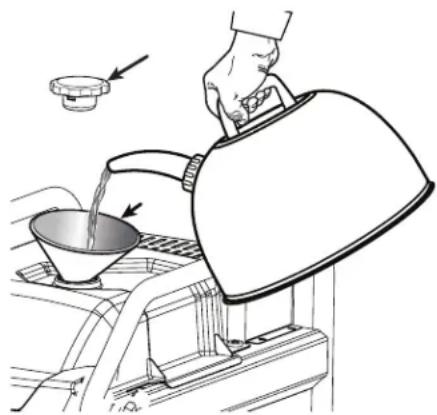
ADDING FUEL

DANGER: RISK OF FIRE AND SERIOUS BURNS: NEVER REMOVE FUEL CAP WHEN UNIT IS RUNNING. SHUT OFF ENGINE AND ALLOW THE UNIT TO COOL AT LEAST FIVE MINUTES. REMOVE CAP SLOWLY.

WARNING: GASOLINE AND ITS VAPORS ARE HIGHLY FLAMMABLE AND EXPLOSIVE. TO PREVENT SERIOUS PERSONAL INJURY AND PROPERTY DAMAGE, HANDLE GASOLINE WITH
CARE. KEEP AWAY FROM IGNITION SOURCES, HANDLE OUTDOORS ONLY, DO NOT SMOKE WHILE ADDING FUEL, AND WIPE UP SPILLS IMMEDIATELY.
When adding gas to the generator, make sure the unit is sitting on a flat, level surface. If the engine is hot, let the generator cool for five minutes before adding gas. ALWAYS fill the fuel tank outdoors with the machine turned off.
- Turn the fuel valve to the OFF position.
- Remove the fuel cap slowly.
- Fill the fuel tank to 1 in. below the top of the fuel neck.
- Replace and secure the fuel cap.

WARNING: ALWAYS SHUT OFF ENGINE BEFORE FUELING. NEVER REMOVE FUEL CAP OR ADD FUEL TO A MACHINE WITH A RUNNING OR HOT ENGINE. MAKE SURE THE UNIT IS SITTING ON A FLAT, LEVEL SURFACE AND ONLY ADD FUEL OUTDOORS. IF THE ENGINE IS HOT, LET THE UNIT COOL FOR AT LEAST FIVE MINUTES BEFORE ADDING FUEL. AFTER FUELING, IMMEDIATELY REPLACE FUEL CAP AND TIGHTEN SECURELY. MOVE AT LEAST 30 FT. FROM REFUELING SITE BEFORE STARTING ENGINE. DO NOT SMOKE AND STAY AWAY FROM OPEN FLAMES AND SPARKS! FAILURE TO FOLLOW THESE INSTRUCTIONS COULD RESULT IN A FIRE AND CAUSE SERIOUS PERSONAL INJURY.
NOTE: Always use unleaded gasoline with a pump octane rating of 86 or higher. Never use old, stale, or contaminated gasoline, and do not use an oil/gas mixture. Do not allow dirt or water into the fuel tank. Do not use E85 fuel.
natural_image
Illustration of a hand pouring liquid into a container using a portable device (no text or symbols)STARTING THE ENGINE:
NOTICE: On a level surface with the engine off, check the lubricant level before each use of the generator.
NOTE: If location of generator is not level, the unit may not start or may shut down during operation.
- Unplug all loads from the generator.
- Turn the fuel valve to the ON position.
- Turn engine switch to the run position.
- Pull the choke button out to the CLOSE/START position
- Pull the recoil starting grip until the engine runs.
NOTE: Do not allow the grip to snap back after starting; return it gently to its original place.

CAUTION: DO NOT CONNECT APPLIANCES WITH DEFECTIVE LINES AND/OR PLUGS.
BE SURE APPLIANCES ARE NOT CONNECTED TO GENERATOR WHEN STARTING UP. STARTING THE GENERATOR WITH AN APPLIANCE CONNECTED COULD RESULT IN DAMAGE TO THE GENERATOR AND/OR APPLIANCE AND PERSONAL INJURY.
STOPPING THE ENGINE
To stop the engine under normal operating conditions:
- Remove any load from the generator.
- Turn the Start/Stop Switch to OFF position.

WARNING: WHILE OPERATING AND STORING, KEEP AT LEAST 3 FEET OF CLEARANCE ON ALL SIDES OF THIS PRODUCT, INCLUDING OVERHEAD. ALLOW A MINIMUM OF 30 MINUTES OF "COOL DOWN" TIME BEFORE STORAGE. HEAT CREATED BY MUFFLER AND EXHAUST GASES COULD BE HOT ENOUGH TO CAUSE SERIOUS BURNS AND/OR IGNITE COMBUSTIBLE OBJECTS.
Your engine is configured for operation below altitudes of 2,000 feet or 3,000 feet at the factory. Your engine must be reconfigured for operation above the preconfigured altitude. Operating the engine with the wrong engine configuration at a given altitude may increase its emissions, decrease fuel efficiency, degrade performance, and cause irreversible damage. Engines configured for high altitude operation cannot be operated in standard altitude conditions. A qualified service center should ensure that your engine is properly configured for your location.
natural_image
Technical line drawing of a mechanical component with no visible text or symbols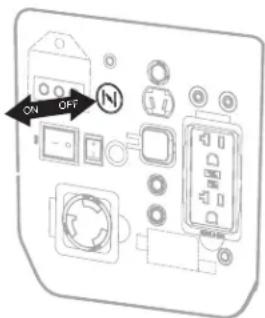
natural_image
Technical line drawing of a mechanical assembly with a hand operating a component (no text or symbols visible)| Recommended Lubricant Viscosities for Ambient Temperature | ||||
| Oil Viscosities | °C °F | |||
| Min | Max Min | Max | ||
| SAE 0W-40 -40 | 40 -40 | 104 | ||
| SAE 5W-40 -30 | 50 -22 | 122 | ||
| SAE 10W-30 - 18 | 40 | 0 | 104 | |
| SAE 15W-40 | -10 | 50 | 14 | 122 |
MAINTENANCE
Normal maintenance, replacement or repair of emission con-trol devices and systems may be performed by any qualified repair establishment or individual with original or equivalent parts. Warranty and recall repairs must be performed by an authorized service center; please contact customer service for assistance.

WARNING: BEFORE INSPECTING, CLEANING OR SERVICING THE MACHINE, SHUT OFF ENGINE, WAIT FOR ALL MOVING PARTS TO STOP, AND DISCONNECT SPARK PLUG WIRE AND MOVE IT AWAY FROM SPARK PLUG. ALLOW 30 MINUTES OF COOL DOWN TIME BEFORE PERFORMING ANY MAINTENANCE. FAILURE TO FOLLOW THESE INSTRUCTIONS CAN RESULT IN SERIOUS PERSONAL INJURY OR PROPERTY DAMAGE.

WARNING: WHEN SERVICING, USE ONLY RECOMMENDED OR EQUIVALENT REPLACEMENT PARTS. USE OF ANY OTHER PARTS COULD CREATE A HAZARD OR CAUSE PRODUCT DAMAGE.

WARNING: DO NOT TAMPER WITH, ADJUST, OR MODIFY THE CARBON MONOXIDE (CO) SENSOR MODULE ON YOUR GENERATOR. FAILURE TO FOLLOW THESE INSTRUCTIONS CAN CAUSE THE MONITOR TO MALFUNCTION WHICH CAN RESULT IN DEATH OR SERIOUS PERSONAL INJURY.
NOTICE: Periodically inspect the entire product for damaged, missing, or loose parts such as screws, nuts, bolts, caps, etc. Tighten securely all fasteners and caps and do not operate this product until all missing or damaged parts are replaced. Please contact customer service or a qualified service center for assistance.
GENERAL MAINTENANCE
Keep the generator in a clean and dry environment where it is not exposed to dust, dirt, moisture, or corrosive vapors. Do not allow the cooling air slots in the generator to become clogged with foreign material such as leaves, etc.
Do not use a garden hose to clean the generator. Water entering the fuel system or other internal parts of the unit can cause problems that will decrease the life of the generator.
To clean the unit:
- Use a soft bristle brush and/or vacuum cleaner to loosen and remove dirt and debris.
- Clean air vents with low pressure air that does not exceed 25 psi.
- Wipe the exterior surfaces of the generator with a damp cloth.
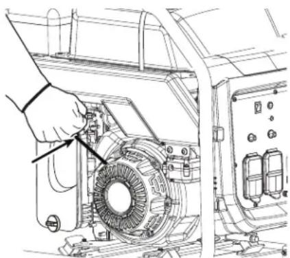
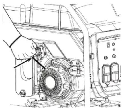
CHECKING/CLEANING AIR FILTER
For proper performance and long life, keep air filter clean.
- Rotate knob counterclockwise to release. Remove cover and set aside.
- Remove the filter element.
- If the filter element is dirty, clean with warm, soapy water. Rinse and let dry.
- Apply a light coat of engine lubricant to the element, then squeeze it out.
- Replace the element in the air filter unit.
- Replace the air filter cover and rotate knob clockwise to secure.
NOTE: Make sure the filter is seated properly inside the generator. Installing the filter incorrectly will allow dirt to enter the engine, causing rapid engine wear.
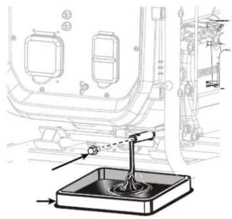
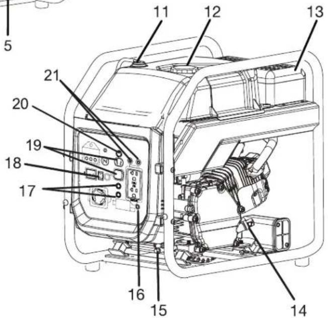
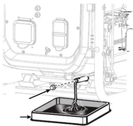
CHANGING ENGINE OIL
For best performance, engine lubricant should be changed after every 100 hours or 6 months of operation.
- Remove the oil fill cap/dipstick.
- Unscrew the oil drain plug and remove.
- Allow lubricant to drain completely into an approved container.
NOTE: Drain the lubricant while the engine is still warm but not hot. Warm lubricant will drain quickly and more completely.

WARNING: DO NOT CHANGE ENGINE LUBRICANT WHILE IT IS HOT. ACCIDENTAL CONTACT WITH HOT ENGINE LUBRICANT COULD RESULT IN SERIOUS BURNS.
- Reinstall the oil drain plug and tighten securely.
- Refill with lubricant following the instructions in the Checking/Adding Lubricant section. For amount of lubricant needed to refill, see Product Specifications earlier in this manual or the accompanying engine manual, if applicable.
- Replace and secure the oil cap/dipstick.
NOTE: Used lubricant should be disposed of at an approved disposal site. See your local retailer for more information.
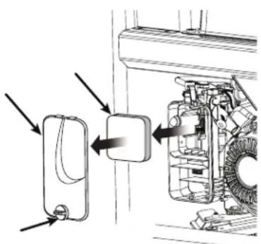
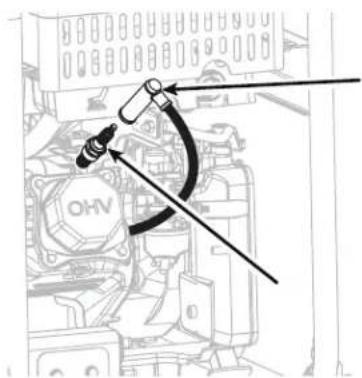
SPARK PLUG
The spark plug must be properly gapped and free of deposits in order to ensure proper engine operation. To check:
- Remove the spark plug cap.
- Clean any dirt from around base of spark plug.
- Remove spark plug using spark plug wrench or socket.
- Inspect spark plug for damage, and clean with a wire brush before reinstalling. If insulator is cracked or chipped, spark plug should be replaced. For replacement spark plug, see Product Specifications earlier in this manual or the accompanying engine manual, if applicable.
-
Measure plug gap. The correct gap is 0.024–0.028 in. (0.60-0.70 mm). To widen gap, if necessary, carefully bend the ground (top) electrode. To lessen gap, gently tap ground electrode on a hard surface.
-
Seat spark plug in position; thread in by hand to prevent cross-threading.
-
Tighten with wrench to compress washer. If spark plug is new, use 1/2 turn to compress washer appropriate amount. If reusing old spark plug, use 1/8 to 1/4 turn for proper washer compression.
NOTE: An improperly tightened spark plug will become very hot and could damage the engine.
- Reintall the spark plug cap.
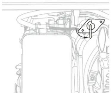
SPARK ARRESTOR
NOTICE: This product is equipped with a spark arrestor that has been evaluated by the USDA Forest Service; however, product users must comply with Federal, State, and local fire prevention regulations. Check with appropriate authorities. Contact customer service or a qualified service center to purchase a replacement spark arrestor.
The spark arrestor must be cleaned or replaced every 50 hours or yearly to ensure proper performance of your product. Spark arrestors may be in different locations depending on the model purchased. Contact customer service or a qualified service center for the location of the spark arrestor for your model.
To clean the spark arrestor:
- Loosen the screw on the spark arrestor cap. Remove the cap and spark arrestor.
- Use a brush (not provided) to remove carbon deposits from the spark arrestor.
- Replace the spark arrestor and cap, tighten screw securely.
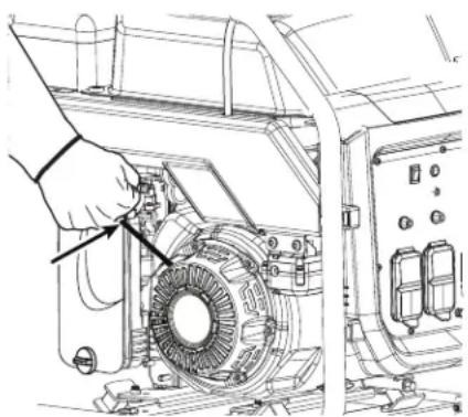
DRAINING FUEL TANK/CARBURETOR
To help prevent gum deposits in the fuel system, drain the fuel from the tank and carburetor before storing.
DRAINING THE FUEL TANK
- Place the fuel valve in the OFF position.
- Remove the fuel line from the hose barb by squeezing the ends of the retaining clip and sliding the fuel line off.
NOTE: Make sure you are removing the fuel line that runs between the fuel valve and the carburetor, NOT the line that runs between the fuel valve and the fuel tank. - Install one end of a drain line (not provided) over the hose barb, and place the other end in a fuel container large enough to catch the fuel being drained from the tank.
- Place the fuel valve in the ON position.
- When the fuel has drained from the tank, place the fuel valve in OFF position and reinstall fuel line securely onto the hose barb.
DRAINING THE CARBURETOR
- Place the fuel valve in the OFF position.
- Position a suitable container under the carburetor drain screw to catch fuel; loosen the screw.
- Allow fuel to drain completely into container.
- Retighten drain screw.
NOTE: Consult hazardous waste management guidelines in your area for the proper way to dispose of used fuel.
| Maintenance Item Before each use Every 20 | hours (first month) | Every 50 hours (3 months) | Every 100 hours (6 months) | Every 300 hours (yearly) | |
| Check Engine Oil. • | |||||
| Change Engine Oil. ^2 | • | • | |||
| Check Air Element. • | |||||
| Clean Air Element. • | |||||
| Replace Air Element. ^2 | • | ||||
| Check-Adjust Spark Plug. • | |||||
| Replace Spark Plug. ^2 | • | ||||
| Clean Spark Arrester • | |||||
| Check-Adjust Valve Clearance ^1,2 | • | ||||
| Clean Fuel Tank and Fuel Filter • | |||||
| Check Fuel Line • | |||||
| Fuel Filter Inspect Replace | |||||
| Check all Hose Connections | • | • | |||
| Recharge Battery (if equipped) | • | ||||
| Inspect fuel tank vapor vent (if equipped) | • | • | |||
| Inspect Carbon Canister (CARB Models only) | • | • | |||
- These items should only be carried out by qualified service center.
- See engine manual for maintenance schedule for this item.
Note: Maintenance should be performed more frequently when generator is used in dusty areas. When generator has exceeded the maximum figures specified in the table, maintenance should still be cycled according to the intervals of time or hours stated herein.
STORAGE
PREPARATION FOR STORAGE
When preparing the generator for storage, allow the unit to cool for 30 minutes then follow the guidelines below.
STORAGE LESS THAN 2 MONTHS
Drain gasoline from tank and dispose of in a suitable container according to state and local ordinances.
STORAGE 2 MONTHS TO 1 YEAR
Drain fuel from carburetor.
Drain gasoline from tank and dispose of in a suitable container according to state and local ordinances.
STORAGE 1 YEAR OR MORE
Drain fuel from the carburetor.
Remove spark plug.
Drain gasoline from tank and dispose of in a suitable container according to state and local ordinances.
Put a tablespoon of engine lubricant into the spark plug cylinder. Turn the engine slowly with the pull rope to distribute the lubricant.
Reinstall spark plug.
Change engine lubricant.
AFTER REMOVAL FROM STORAGE:
Fill with fresh gasoline.

WARNING: GASOLINE IS EXTREMELY FLAMMABLE AND IS EXPLOSIVE UNDER CERTAIN CONDITIONS. DRAIN THE FUEL IN A WELL-VENTILATED AREA WITH THE ENGINE STOPPED AND COOL. NEVER SMOKE OR ALLOW FLAMES OR SPARKS IN THE AREA DURING THIS PROCEDURE.
NOTE: If storing gasoline in suitable container for later use, make sure gasoline has been treated with fuel stabilizer according to stabilizer manufacturer's instructions.
TROUBLESHOOTING
| Symptom Problem | Solution | |
| Engine Will Not Start | Engine switch is off. Turn engine switch on. | |
| Fuel valve is OFF. Turn fuel valve to ON position. | ||
| No fuel. Fill fuel tank. | ||
| Stale gasoline or water in gasoline. Drain entire system and refill with fresh fuel. | ||
| Lubricant level is low. Engine is equipped with low oil shutdown. If engine lubricant level is low, it must be filled before it will start. Check engine lubricant level and fill, if necessary. | ||
| Spark plug faulty, fouled, or improperly gapped. | Replace spark plug. | |
| Engine stored without treating or draining gasoline, or refueled with bad gasoline. | Drain fuel and carburetor. Refuel with fresh gas-oline. | |
| Dirty fuel filter. Contact a qualified service center. | ||
| CO sensor LED is flashing red, indicating a CO hazard. | Leave area immediately and relocate to an open outdoor area. Ventilate area thoroughly before occupying again. Ensure the generator is located in an open outdoor area and point exhaust away from occupied structures. | |
| CO sensor LED is flashing yellow and/or making an audible chirp, indicating a sensor fault. | The CO sensor needs to be repaired or replaced. Contact customer service or a qualified service center for assistance. | |
| Engine hard to start. | Water in gasoline. Drain entire system and refill with fresh fuel. | |
| Weak spark at spark plug. Contact a qualified service center. | ||
| Engine lacks power. | Engine stored without treating or draining gasoline, or refueled with bad gasoline. | Drain fuel and carburetor. Refuel with fresh gas-oline. |
| Dirty air filter. Clean or replace as needed. | ||
| AC receptacle does not work. | Item plugged in is defective. | Try a different item. |
| Generator is overloaded. | Remove loads and press the reset button. | |
| Circuit breaker is tripped. | Reset the AC circuit breaker. | |
| Generator makes a “spark knock” or “pinging” noise. | An occasional light “knocking” or “pinging” under heavy load is not a cause for concern. However, if the knocking or pinging occurs under normal load at a steady engine speed, the problem may be with the brand of gasoline being used. | Switch to a different brand of gasoline, making sure that the octane rating is 86 or higher. If problem continues, contact a qualified service center. |
If problem persists after trying the above solutions, contact customer service or a qualified service center for assistance.
NOTICE: As the equipment owner, you are responsible for the performance of the required maintenance listed in the Maintenance section. It is recommended that you retain all receipts covering maintenance on your equipment. Neglecting or failing to perform the required maintenance may increase emissions, decrease fuel efficiency, degrade performance, cause irreversible engine damage and/or void your warranty.
SPECIFICATIONS
SPECIFICATIONS
Engine Type .......Single Cylinder, 4-Stroke, Forced Air Cooling
Displacement (cc) 212
Ignition System ......Electronic
Spark Plug Gap .028 - .032 inches (0.7 - 0.8mm)
Fuel Volume 1.85 U.S. gallon (7L)
Fuel Consumption (g/(kW·h) .... ≤ 395
100% load continuous running time (hr) 4
50% load continuous running time (hr) 7
Oil Capacity 0.56 quart (0.53L)
Rated Output (DC) 12V 8.3A
Rated Frequency (Hz) 60
Rated Voltage (V) 120
Rated Output Power (kW) 3.2
Maximum Output Power (kW) 3.5
Phase .......Single
Total Harmonic Distortion ....../< 3%
RECORD SERIAL NUMBER
Write you model number, machine serial number (see serial number tag in illustration) and date of purchase in the spaces provided below. Your dealer needs this information when ordering parts.
Model No.
Machine Serial No.
Date of Purchase
(To be filled in by purchaser)
For use in a weather protected area only?
Mi-T-M warrants all parts, (except those referred to below), of your new generator to be free from defects in materials and workmanship during the following periods:
For One (1) Years from the date of original purchase.
Defective parts not subject to normal wear and tear will be repaired or replaced at our option during the warranty period. In any event, reimbursement is limited to the purchase price paid.
EXCLUSIONS
- Engine/Motor and Generator are covered under separate warranty by its respective manufacturer and is subject to the terms set forth therein.
- This warranty does not cover parts damaged due to normal wear, misapplication, misuse, operation at other than recommended. Failure to follow recommended operating and maintenance procedures also voids warranty.
- The use of other than genuine manufacturer repair parts will void warranty.
- Parts returned, prepaid to our factory or to an Authorized Mi-T-M Service Center will be inspected and replaced free of charge if found to be defective and subject to warranty. There are no warranties which extend beyond the description of the face hereof. Under no circumstances shall the manufacturer bear any responsibility for loss of use of the unit, loss of time or rental, inconvenience, commercial loss or consequential damages.
For Service or Warranty Consideration, contact Mi-T-M® Corporation, 50 Mi-T-M Drive, Peosta, IA 52068 563-556-7484 / 800-553-9053 / Fax 563-556-1235 Monday - Friday 8:00 a.m. - 5:00 p.m. CST
EXHAUST AND EVAPORATIVE EMISSIONS CONTROL WARRANTY STATEMENT YOUR WARRANTY RIGHTS AND OBLIGATIONS
The California Air Resources Board, the United States Environmental Protection Agency (EPA) and Mi-T-M are pleased to explain the emission control system's warranty on your 2022/2023 small off-road engine/equipment (SORE). In California, new equipment that use small off-road engines must be designed, built and equipped to meet the State's stringent anti-smog standards. Mi-T-M must warrant the exhaust and evaporative emissions control system (E & EECS) on your SOREs for the period listed below provided there has been no abuse, neglect or improper maintenance of your equipment leading to the failure of the evaporative emission control system.
Your E & EECS may include parts such as the carburetor, fuel tanks, fuel lines (for liquid fuel and fuel vapors), fuel caps, valves, canisters, filters, clamps, connectors, and other associated components. Where warrantable conditions exist, Mi-T-M will repair your small off-road engine at no cost to you including diagnosis, parts and labor.
MANUFACTURER'S WARRANTY COVERAGE:
This E & EECS is warranted for two years. If any evaporative emissions-related part on your small off-road engine/equipment is defective, the part will be repaired or replaced by Mi-T-M.
OWNER'S WARRANTY RESPONSIBILITIES:
-As the SORE owner, you are responsible for performance of the required maintenance listed in your owner's manual. Mi-T-M recommends that you retain all receipts covering maintenance on your SORE, but Mi-T-M cannot deny warranty coverage solely for the lack of receipts.
-As the SORE owner, you should be aware that Mi-T-M may deny you warranty coverage if your SORE or a part has failed due to abuse, neglect, or improper maintenance or unapproved modifications.
-You are responsible for presenting your SORE to distribution center or service center authorized by Mi-T-M Corporation, 50 Mi-T-M Drive, Peosta, IA 52068 (herein Mi-T-M) as soon as the problem exists. The warranty repairs shall be completed in a reasonable amount of time, not to exceed 30 days.
If you have a question regarding your warranty coverage, you should contact Mi-T-M Customer Service Department at 1-800-553-9053 or by emailing us at corp@mitm.com.
GENERAL EMISSIONS WARRANTY COVERAGE
MI-T-M WARRANTS TO THE ULTIMATE PURCHASER AND EACH SUBSEQUENT PURCHASER THAT THE SORE (1) HAS BEEN DESIGNED, BUILT AND EQUIPPED SO AS TO CONFORM WITH ALL APPLICABLE REGULATIONS; AND (2) IS FREE FROM DEFECTS IN MATERIALS AND WORKMANSHIP THAT CAUSE THE FAILURE OF A WARRANTED PART TO CONFORM WITH THOSE REGULATIONS AS MAY BE APPLICABLE TO THE TERMS AND CONDITIONS STATED BELOW.
(a) The warranty period begins on the date the engine is delivered to an ultimate purchaser or first placed into service. The warranty period is two years.
(b) Subject to certain conditions and exclusions as stated below, the warranty on emissions related parts is as follows:
(1) Any warranted part that is not scheduled for replacement as required maintenance in your owner's manual is warranted for the warranty period stated above. If the part fails during the period of warranty coverage, the part will be repaired or replaced by Mi-T-M according to subsection (4) below. Any such part repaired or replaced under warranty will be warranted for the remainder of the period.
(2) Any warranted part that is scheduled only for regular inspection in your owner's manual is warranted for the warranty period stated above. Any such part repaired or replaced under warranty will be warranted for the remaining warranty period.
(3) Any warranted part that is scheduled for replacement as required maintenance in your owner's manual is warranted for the period of time before the first scheduled replacement date for that part. If the part fails before the first scheduled replacement, the part will be repaired or replaced by Mi-T-M according to subsection (4) below. Any such part repaired or replaced under warranty will be warranted for the remainder of the period prior to the first scheduled replacement point for the part.
(4) Repair or replacement of any warranted part under the warranty provisions herein must be performed at a warranty station at no charge to the owner.
(5) Not withstanding the provisions herein, warranty services or repair will be provided at all of our distribution centers that are franchised to service the subject engines.
(6) The owner must not be charged for diagnostic labor that leads to the determination that a warranted part is in fact defective, provided that such diagnostic work is performed at a warranty station.
(7) Throughout the engine warranty period stated above, Mi-T-M will maintain a supply of warranted parts sufficient to meet the expected demand for such parts.
(8) Any replacement parts that do not increase the exhaust or evaporative emissions of the engine or evaporative emission control system must be used in the performance of any warranty maintenance or repairs and must be provided without charge to the owner. Such use will not reduce the warranty obligations of Mi-T-M.
(9) Add-on or modified parts that are not exempted by the Air Resources Board may not be used. The use of any non-exempted add-on or modified parts by the ultimate purchaser will be grounds for disallowing a warranty claims. Mi-T-M will not be liable to warrant failures of warranted parts caused by the use of a non-exempted add-on or modified part.
(10) Mi-T-M shall provide any documents that describe that Mi-T-M warranty procedures or policies within five working days of request by the Executive Officer.
(c) WARRANTED PARTS:
The repair or replacement of any warranted part otherwise eligible for warranty coverage may be excluded from such warranty coverage if Mi-T-M demonstrates that the engine has been abused, neglected, or improperly maintained, and that such abuse, neglect, or improper maintenance was the direct cause of the need for repair or replacement of the part. That notwithstanding, any adjustment of a component that has a factory installed, and properly operating, adjustment limiting device is still eligible for warranty coverage. The following emissions warranty parts list are covered.
(1) Fuel Tank*
(2) Fuel Cap
(3) Fuel Lines (for liquid fuel and fuel vapors)
(4) Fuel Line Fittings
(5) Clamps*
(6) Pressure Relief Valves*
(7) Control Valves*
(8) Control Solenoids*
(9) Electronic Controls*
(10) Vacuum Control Diaphragms*
(11) Control Cables*
(12) Control Linkages*
(13) Purge Valves*
(14) Gaskets*
(15) Liquid/Vapor Separator
(16) Carbon Canister
(17) Canister Mounting Brackets
(18) Carburetor Purge Port Connector
* Note: As they relate to the evaporative emission control system.
(i) Carburetor and internal parts (and/or pressure regulator or fuel injection system).
(ii) Air/fuel ratio feedback and control system.
(iii) Cold start enrichment system.
(2) Air Induction System
(i) Controlled hot air intake system.
(ii) Intake manifold.
(iii) Air filter.
(3) Ignition System
(i) Spark Plugs.
(ii) Magneto or electronic ignition system.
(iii) Spark advance/retard system.
(4) Exhaust Gas Recirculation (EGR) System
(i) EGR valve body, and carburetor spacer if applicable.
(ii) EGR rate feedback and control system.
(5) Air Injection System
(i) Air pump or pulse valve.
(ii) Valves affecting distribution of flow.
(iii) Distribution manifold.
(6) Catalyst or Thermal Reactor System
(i) Catalytic converter.
(ii) Thermal reactor.
(iii) Exhaust manifold.
(7) Particulate Controls
(i) Traps, filters, precipitators, and any other device used to capture particulate emissions.
(8) Miscellaneous Items Used in Above Systems
(i) Electronic controls.
(ii) Vacuum, temperature, and time sensitive valves and switches.
(iii) Hoses, belts, connectors, and assemblies.
INTRODUCTION
natural_image
Black triangular warning symbol with exclamation mark (no text or numbers)COMPRENDRE LES MOTS D'ALERTE
natural_image
Abstract black-and-white graphic of a stylized bird perched on a human figure, with no text or symbols present.DANGERDANGERPELIGRO
!
Using a generator indoors CAN KILL YOU IN MINUTES. Generator exhaust contains carbon monoxide. This is a poison you cannot see or smell.
NEVER use inside a home or garage, EVEN IF doors and windows are open. Only use OUTSIDE and far away from windows, doors, and vents.
RISQUES ÉLECTRIQUES

LA GÉNÉRATRICE (ENROULEMENT DU STATOR) ES ISOLÉE DU CADRE ET DE LA FICHE DE TERRE DU BOÎTIER DE LA PRISE DE COURANT
LES APPAREILS ÉLECTRIQUES QUI NÉCESSITENT UNE MISE À LA TERRE NE FONCTIONNERONT PAS SI LA FICHE DE TERRE N'EST PAS FONCTIONELLE.
LES APPAREILS ÉLECTRIQUES, QUI NÉCESSITENT UNE BROCHE FEMELLE MISE À LA TERRE NE FONCTIONNERONT PAS SI LE RÉCEPTACLE N'EST PAS FONCTIONNEL.

ATTENTION: NE SERT PAS À COUPER LE COURANT.
natural_image
Black-and-white icon of a hand with a lightning bolt and smoke trail, symbolizing electrical hazard (no text or symbols)natural_image
Illustration of a person wearing various safety gear and footwear, including helmet, gloves, and shoes (no text or symbols)PRÉPARATION POUR LES URGENCES
natural_image
Illustration of a first aid kit, fire extinguisher, and medical kit with cross symbols (no text or labels)INSPECTER LE GROUPE ÉLECTROGÈNE
FLASHING RED INDICATOR = Automatic Shutoff Event. Leave area immediately and relocate to an open outdoor area. Ventilate area thoroughly before occupying again. Ensure the generator is located in an open outdoor area. MOVE TO FRESH AIR AND GET MEDICAL HELP IF SICK, DIZZY OR WEAK.

CONSTANT YELLOW INDICATOR = System Fault. Contact Dealer.
34-4055
⚠ AVERTISSEMENT

DÉTECTION DE MONOXYDE DE CARBONE.
Using a generator indoors CAN KILL YOU IN MINUTES. Generator exhaust contains carbon monoxide. This is a poison you cannot see or smell.
NEVER use inside a home or garage, EVEN IF doors and windows are open.
Only use OUTSIDE and far away from windows, doors, and vents.
34-4056/100121
34-4056
WARNING
WARNING: Cancer and Reproductive Harm — www.P65warnings.ca.gov/SHOCK: A generator is a potential shock hazard which can result in serious injury or death.
- Generator must be kept dry and MUST be grounded before use. See operators manual for specific instructions.
• Always keep generator three (3) feet from any structure.
EXPLOSIVE FUEL: Gasoline is extremely flammable and its vapors can explode if ignited causing serious injury or death.
- Do NOT fill fuel tank while engine is hot or running.
⚠ AVERTISSEMENT/ADVERTENCIA
natural_image
Black-and-white icon of a hand with a lightning bolt and smoke trail, symbolizing electrical hazard (no text or symbols)natural_image
Technical line drawing of a mechanical device with circular components and directional arrows indicating motion (no text or symbols)
natural_image
Technical illustration of a mechanical assembly with a hand operating a component (no text or symbols visible)natural_image
Illustration of a hand pouring liquid into a container using a portable device (no text or symbols visible)AVANT D'AJOUTER DE L'ESSENCE. REMETTRE IMMÉDIATEMENT LE BOUCHON DU RÉSERVOIR D'ESSENCE ET LE SERRER FERMEMENT. S'ÉLOIGNER D'AU MOINS 9 M (30 PI) DU POINT DE RAVITAILLEMENT AVANT DE LANÇER LE MOTEUR. NE PAS FUMER, ET RESTER À L'ÉCART DES FLAMMES VIVES ET DES ÉTINCELLES ! NE PAS RESPECTER CES INSTRUCTIONS REPRÉSENTE UN RISQUE D'INCENDIE ET DE BLESSURES GRAVES.
natural_image
Technical line drawing of a mechanical component with no visible text or symbols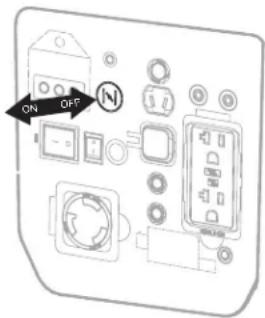
natural_image
Technical line drawing of a mechanical assembly with a hand operating a motor stator (no text or symbols present)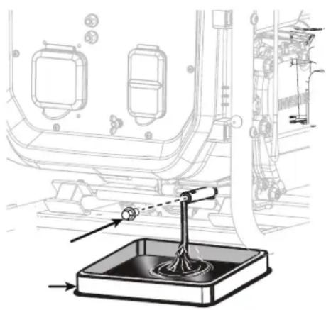
natural_image
Technical line drawing of a mechanical assembly with a lever and base component (no text or symbols)ENTRETIEN DE LA BOUGIE
VIDANGE DU RÉSERVOIR DE CARBURANT/ CARBURATEUR
CONDITIONS DE LA GARANTIE
natural_image
Black triangular warning symbol with exclamation mark (no text or numbers)COMPRENDA PALABRAS DE ALERTAS
natural_image
Abstract black-and-white graphic of a bird-like figure with a circular head, set against a dotted background (no text or symbols)Using a generator indoors CAN KILL YOU IN MINUTES. Generator exhaust contains carbon monoxide. This is a poison you cannot see or smell.
NEVER use inside a home or garage, EVEN IF doors and windows are open.
Only use OUTSIDE and far away from windows, doors, and vents.
natural_image
Black starburst graphic symbol on white background (no text or symbols)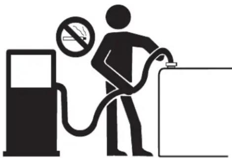
natural_image
Silhouette of a person refueling a fuel pump with a no-smoking symbol (no text or labels)RIESGOS DE ELECTRICOS

natural_image
Black-and-white illustration of a hand with a lightning bolt and smoke trail, symbolizing electrical hazard (no text or symbols)natural_image
Illustration of a person wearing various safety gear and clothing (no text or symbols)natural_image
Illustration of a first aid kit, fire extinguisher, and medical kit with cross symbols (no text or labels)FLASHING RED INDICATOR = Automatic Shutoff Event. Leave area immediately and relocate to an open outdoor area. Ventilate area thoroughly before occupying again. Ensure the generator is located in an open outdoor area. MOVE TO FRESH AIR AND GET MEDICAL HELP IF SICK, DIZZY OR WEAK.

CONSTANT YELLOW INDICATOR = System Fault. Contact Dealer.
⚠ AVERTISSEMENT

DÉTECTION DE MONOXYDE DE CARBONE.
Using a generator indoors CAN KILL YOU IN MINUTES. Generator exhaust contains carbon monoxide. This is a poison you cannot see or smell.
NEVER use inside a home or garage, EVEN IF doors and windows are open.
Only use OUTSIDE and far away from windows, doors, and vents.
34-4056
WARNING
WARNING: Cancer and Reproductive Harm — www.P65warnings.ca.gov/SHOCK: A generator is a potential shock hazard which can result in serious injury or death.
- Generator must be kept dry and MUST be grounded before use. See operators manual for specific instructions.
- Always keep generator three (3) feet from any structure. PLOSIVE FUEL: Gasoline is extremely flammable and its vapors can explode if ignited using serious injury or death.
- Do NOT fill fuel tank while engine is hot or running.
⚠ AVERTISSEMENT/ADVERTENCIA
natural_image
Black-and-white icon of a hand with a lightning bolt and serrated cable, symbolizing electrical hazard (no text or symbols)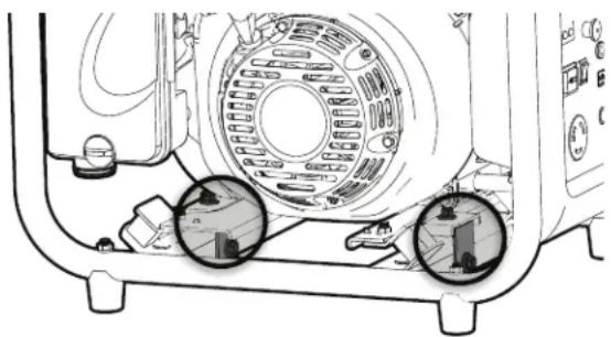
natural_image
Technical diagram of a mechanical device showing internal components and two circular insets (no text or symbols)
natural_image
Technical line drawing of a mechanical assembly with a hand holding a tool, showing internal components and motion indicators (no text or symbols)natural_image
Illustration of a hand pouring liquid into a container using a kettle (no text or symbols)ARRANQUE DEL MOTOR
natural_image
Technical line drawing of a mechanical component with no visible text or symbols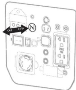
natural_image
Technical line drawing of a mechanical assembly with a hand operating a component (no text or symbols visible)| Viscosidad recomendada del lubricante a temperatu-ra ambiente | ||||
| Viscosidad del aceite | °C °F | |||
| Min Max Min Max | ||||
| SAE 0W-40 -40 | 40 -40 | 104 | ||
| SAE 5W-40 -30 | 50 -22 | 122 | ||
| SAE 10W-30 - 18 | 40 | 0 | 104 | |
| SAE 15W-40 | -10 | 50 | 14 | 122 |
natural_image
Technical line drawing of a vehicle interior showing a lever and base with no visible text or symbolsDate of manufacture / Date de fabrication: 2021-1 2 3 4 5 6 7 8 9 10 11 12
For use in a weather protected area only!
Lunes - Viernes 8:00 a.m. - 5:00 p.m. CST
Manufactured by Mi-T-M
50 Mi-T-M Drive, Peosta IA 52068
563-556-7484/ Fax 563-556-1235