380940 - Lamp Kichler - Free user manual and instructions
Find the device manual for free 380940 Kichler in PDF.


User questions about 380940 Kichler
0 question about this device. Answer the ones you know or ask your own.
Ask a new question about this device
Download the instructions for your Lamp in PDF format for free! Find your manual 380940 - Kichler and take your electronic device back in hand. On this page are published all the documents necessary for the use of your device. 380940 by Kichler.
USER MANUAL 380940 Kichler
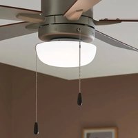
Universal LED Light Kit
Product images may vary slightly from actual product.
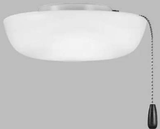
natural_image
White ceiling lamp with a hanging black handle and chain of white paper tape (no text or symbols visible)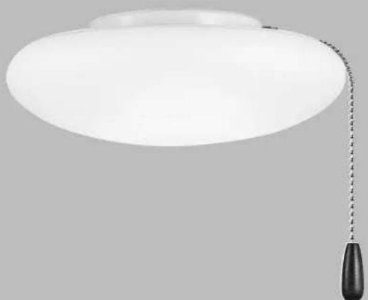
natural_image
White circular pendant light with a black hanging chain, against a plain gray background (no text or symbols)INSTRUCTION MANUAL
Model#: 380940, 380941, 380960
380961,380980,380981
READ AND SAVE THESE INSTRUCTIONS
REV.17-APR-2023
TABLE OF CONTENTS
SAFETY RULES 3
PACKAGE CONTENTS....4
SELECTING COLOR TEMPERATURE ....5
INSTALLING THE LIGHT KIT ....6
FCC INFORMATION......8
COMPATIBILITY....9
SAFETY RULES
- CAUTION – RISK OF SHOCK: Disconnect power at the main circuit breaker panel or main fusebox before starting and during the installation.
- WARNING: All wiring must be in accordance with the National Electrical Code "ANSI/NFPA 70" and local electrical codes. Electrical installation should be performed by a qualified licensed electrician.
- WARNING: make sure the power is disconnected before cleaning your light kit and fan.
- To avoid personal injury or damage to the light kit, fan, and other items, be cautious when working around or cleaning the light kit and fan.
- Do not use water or detergents when cleaning the light kit, fan, or fan blades. A dry dust cloth or lightly dampened cloth will be suitable for most cleaning.
- Electrical diagrams are reference only. Light kits that are not packed with the fan must be cETLus, cULus, or cCSAus Listed and marked suitable for use with the model fan you are installing. Switches must be cETLus, cULus or cCSAus Listed General Use Switches. Refer to the Instructions packaged with the light kits and switches for proper assembly.
- All set screws must be checked, and retightened where necessary, before installation.
Model#: 380940, 380941 N.W. 0.75 KGS (1.65 LBS) / G.W. 1.00 KGS (2.20 LBS)
Model#: 380960, 380961 N.W. 1.00 KGS (2.20 LBS) / G.W. 1.30 KGS (2.87 LBS)
Model#: 380980, 380981 N.W. 1.90 KGS (4.19 LBS) / G.W. 2.60 KGS (5.73 LBS)
"CAUTION-RISK OF FIRE"
CONSULT A QUALIFIED ELECTRICIAN TO ENSURE CORRECT BRANCH CIRCUIT CONDUCTOR.
PACKAGE CONTENTS
Unpack your light kit and check the contents. You should have the following items:
A. Light Kit (with Rubber Washer preinstalled)
B. Part bag contents:
Hex Nut
Pull Chain Extension and Fob
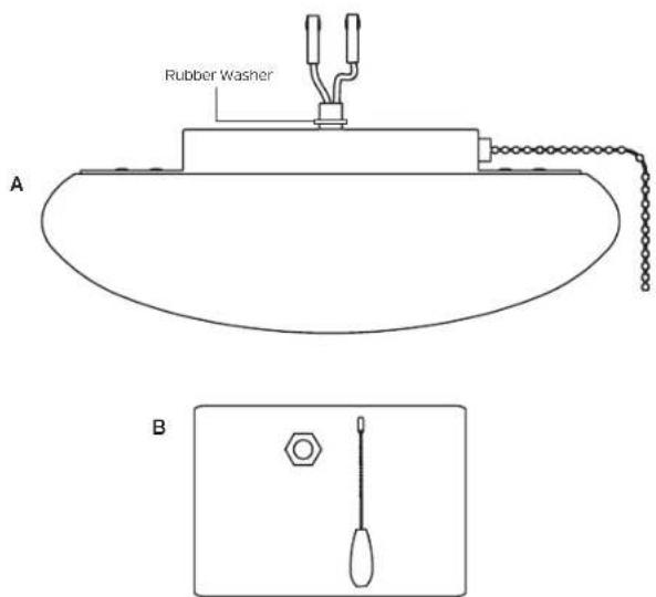
text_image
Rubber Washer A BSELECTING COLOR TEMPERATURE
- On top of the light kit, unscrew the shade locking screw (located near the outer edge of the light plate). Remove the shade locking screw (Fig. 1).
- Unscrew the shade (counterclockwise) from the light plate. Remove the shade.
- Locate the color temperature selection switch on the LED module, and select the desired LED color temperature (CCT1 = 3000K soft white, CCT2 = 5000K daylight) (Fig. 2).
- Raise the shade to the light plate, carefully aligning the three cutouts in the top of the shade with the three shade guides on the bottom of the light plate. Turn the shade (clockwise) into the shade guides until the shade locks in place (Fig. 3).
NOTE: Make sure that the shade is locked into all three of the shade guides.
NOTE: Make sure that when the shade is reinstalled, the hole for the shade locking screw in the light plate is aligned with the hole for the shade locking screw in the shade.
- Reinstall the shade locking screw to secure the shade to the light plate.
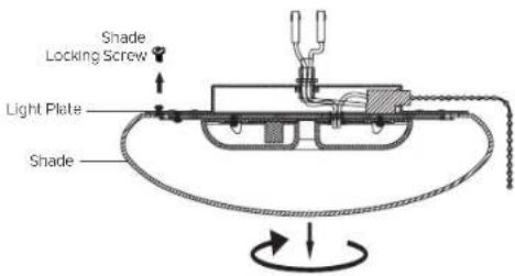
text_image
Shade Locking Screw Light Plate ShadeFig. 1
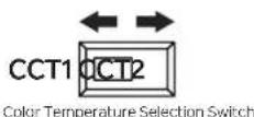
Fig. 2
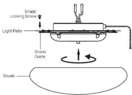
text_image
Shade Locking Screw Light Plate Shade Guide ShadeFig. 3
INSTALLING THE LIGHT KIT
CAUTION – To Reduce The Risk Of Electric Shock, Disconnect The Electrical Supply Circuit To The Fan Before Installing Light Kit.
- Remove the center plug from the switch housing (supplied with the fan). Retain the center plug for future use, in case the light kit is removed later. (Fig. 4).
- Attach the light kit to the switch housing by carefully passing the light kit wires (black and white) through the hole in the bottom of the switch housing, and then screwing the light kit into the hole in the bottom of the switch housing.
- Pass the light kit wires (black and white) through the hex nut and thread the hex nut onto the threaded tube (from the light kit) that is protruding into the switch housing. Tighten the hex nut to secure the switch housing to the light kit, and prevent movement after installation.
- Locate the white and blue wires inside the switch housing labeled FOR LIGHT.
- Attach the wires from the light kit to the wires inside the switch housing by pushing the polarized connections together.
- White wire to White wire
- Blue wire to Black wire
- Attach the pull chain extension and fob to the beaded pull chain on the light kit.
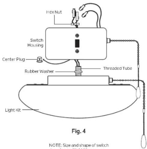
text_image
Hex Nut Switch Housing Center Plug Rubber Washer Threaded Tube Light Kit Fig. 4 NOTE: Size and shape of switchNOTE: Size and shape of switch housing and light kit may vary.
INSTALLING THE LIGHT KIT (continued)
- Raise and hold the light kit assembly close to the mounting plate of the ceiling fan. Push the square wire connectors together. (Fig. 5)
NOTE: The square connectors are color coded. Match the color coded sides of each plug and push. They will attach ONLY when matched correctly.
-
Carefully push all wires back into the switch housing, then install the light kit assembly onto the mounting plate using the 3 switch housing screws. Be sure to tighten all screws. (Fig. 5)
-
Your installation is now complete. Restore electrical power and enjoy your new ceiling fan light kit.
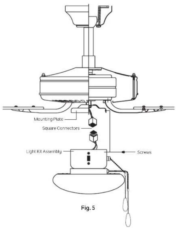
text_image
Mounting Plate Square Connectors Light Kit Assembly Screws Fig. 5FCC INFORMATION
This device complies with part 15 of the FCC Rules. Operation is subject to the following two conditions:
1) This device may not cause harmful interference, and
2) This device must accept any interference received, including interference that may cause undesired operation.
Note: This equipment has been tested and found to comply with the limits for a Class B digital device, pursuant to part 15 of the FCC Rules. These limits are designed to provide reasonable protection against harmful interference in a residential installation. This equipment generates, uses and can radiate radio frequency energy and, if not installed and used in accordance with the instructions, may cause harmful interference to radio communications. However, there is no guarantee that interference will not occur in a particular installation. If this equipment does cause harmful interference to radio or television reception, which can be determined by turning the equipment off and on, the user is encouraged to try to correct the interference by one or more of the following measures:
- Reorient or relocate the receiving antenna.
- Increase the separation between the equipment and receiver.
- Connect the equipment into an outlet on a circuit different from that to which the receiver is connected.
- Consult the dealer or an experienced radio/TV technician for help.
COMPATIBILITY
CAUTION: To Reduce The Risk Of Fire And Electric Shock, This Light Kit Should Be Used Only With The Fan Models Listed Below:
Models 300103, 300107, 300117, 300188, 300206, 300253, 330015, 330018, 330020, 330021, 330160, 330164, 330165, 330241, 330242, 330243, 330247, And 339013 Manufactured By Kichler Lighting LLC.
For an updated list of compatible models, please visit Kichler.com
KICHLER®
www.kichler.com
KICHLER® LIGHTING LLC
30455 SOLON ROAD
SOLON, OHIO 44139
CUSTOMER SERVICE 866.558.5706
8:00 AM TO 5:00 PM EST, MONDAY - FRIDAY
REV. 17-APR-2023
© Kichler Lighting LLC. All Rights Reserved.
KICHLER®
natural_image
White ceiling lamp with a hanging black handle and a small black handle, against a plain gray background (no text or symbols visible)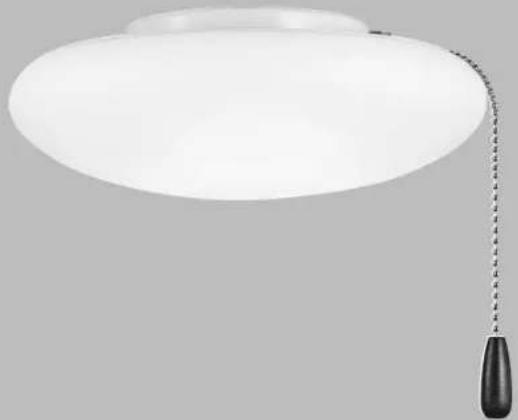
natural_image
White circular pendant light with a black handle, against a plain gray background (no text or symbols)MANUEL D'INSTRUCTIONS
INFORMATIONS FCC....8
COMPATIBILITÉ....9