Profile PHP6030DWBB - Cooker GE - Free user manual and instructions
Find the device manual for free Profile PHP6030DWBB GE in PDF.

User questions about Profile PHP6030DWBB GE
0 question about this device. Answer the ones you know or ask your own.
Ask a new question about this device
Download the instructions for your Cooker in PDF format for free! Find your manual Profile PHP6030DWBB - GE and take your electronic device back in hand. On this page are published all the documents necessary for the use of your device. Profile PHP6030DWBB by GE.
USER MANUAL Profile PHP6030DWBB GE
Installation Instructions
30 and 36" Electric Cooktop - Induction
Questions? Call us at 1.800.432.2737 or visit GEAppliances.com.
In Canada, call 1.800.561.3344 or visit GEAppliances.ca.
BEFORE YOU BEGIN
Read these instructions completely and carefully.
- IMPORTANT — Save these instructions for local inspector's use.
• IMPORTANT — Observe all governing codes and ordinances. - Note to Installer – Be sure to leave these instructions with the Consumer.
- Note to Consumer – Keep these instructions for future reference.
- Product failure due to improper installation is not covered under the Warranty.
WARNING
This appliance must be properly
grounded.
. ATTENTION INSTALLER
— ALL COOKTOPS MUST BE HARD WIRED (DIRECT WIRED) INTO AN APPROVED JUNCTION BOX. A "PLUG AND RECEPTACLE" IS NOT PERMITTED ON THESE PRODUCTS.
- Proper installation is the responsibility of the installer and product failure due to improper installation is NOT covered under warranty.
- Consider recycling options for your appliance packaging material.
MATERIALS YOU WILL NEED
Junction Box (Sized for conduit per local electrical codes.)
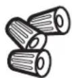
Large Size Wire Nuts
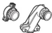
90° or Straight Squeeze Connector for 1" Conduit
TOOLS YOU MAY NEED

Pencil
Saber Saw
Phillips Head
Screwdriver
1/8" Drill Bit & Electric or Hand Drill

1/4" Nut Driver
Ruler or Straightedge
Safety Glasses

Gloves
CUTTING THE COUNTERTOP
If you are installing the cooktop in a solid surface material such as granite, quartz or any other natural or synthetic solid surface, we recommend that the cutout be prepared by a professional cabinet or countertop installer.
Cooktop cutouts in wood or wood-laminate countertops may be able to be prepared using a saber saw and electric drill.
IMPORTANT SAFETY INSTRUCTIONS
FOR YOUR SAFETY
- For Personal Safety, remove house fuse or open circuit breaker before beginning installation. Failure to do so could result in serious injury or death.
- Be sure your cooktop is installed properly by a qualified installer or service technician.
-
To eliminate the risk of burns or fire due to reaching over heated surface elements, cabinet storage located above the surface units should be avoided. If cabinet storage space is to be provided, the risk can be reduced by installing a range hood that projects horizontally a minimum of 5" beyond the bottom of the cabinets. Cabinet installation above the cooktop may be no deeper than 13".
-
Make sure the cabinets and wall coverings around the cooktop can withstand the temperatures (up to 200°F) generated by the cooktop.
- The cooktop should be easy to reach and lighted with natural light during the day.
- Always disconnect the electrical service to the cooktop before repairing or servicing the cooktop. This can be done by disconnecting the fuse or circuit breaker. Failure to do this could result in a dangerous or fatal shock. Know where your main disconnect switch is located. If you do not know, have your electrician show you.
NOTE TO ELECTRICIAN: The power leads supplied with this appliance are UL recognized for connections to larger gauge household wiring. The insulation of these leads is rated at temperatures much higher than the temperature rating of household wiring. The current carrying capacity of a conductor is governed by the wire gauge and also the temperature rating of the insulation around the wire.
NOTE: ALUMINUM WIRING
WARNING
INSTALLATIONS WITH ALUMINUM
HOUSE WIRING REQUIRE ATTENTION:
A. Improper connection of Aluminum house wiring to appliance copper leads can result in an electrical hazard or fire. Use only connectors designed
for joining copper to aluminum and follow the manufacturer's recommend procedure closely.
B. Aluminum to Copper wiring connections must conform with the National Electrical code, local codes and industry-accepted wiring practices.
C. If an anti-oxidant compound is added to the wiring connectors, the compound should be UL-Listed and suitable for the application materials, voltage and temperature.
D. Connectors for joining Aluminum and Copper wiring may be larger in size than standard connectors. It is recommended to use a double-gang, or larger, electrical box to enclose the connectors joining Aluminum and Copper wiring.
ELECTRICAL REQUIREMENTS
This appliance must be supplied with the proper voltage and frequency, and connected to an individual, properly grounded branch circuit, protected by a circuit breaker or a time delay fuse as noted on name plate and on the chart below.
| KW Rating240V | KW Rating208V | RecommendedCircuit Size(Dedicated) |
| 4.9 KW–7.2 KW 4.2 | KW–6.2 KW 30 Amp | |
| 7.3 KW–9.6 KW 6.3 | KW–8.3 KW 40 Amp |
We recommend you have the electrical wiring and hookup of your cooktop connected by a qualified electrician. After installation, have the electrician show you where your main cooktop disconnect is located.
Wiring must conform to National Electrical Code and all local electrical codes. You can get a copy of the National Electrical Code, ANSI/NFPA No. 70-Latest Edition, by writing to:
National Fire Protection Association
Batterymarch Park
Quincy, MA 02269
In Canada, wiring must conform to Canadian Electrical Code (CEC).
The cooktop conduit wiring is approved for copper wire connection only, and if you have aluminum house wiring, you must use special UL approved connectors for joining copper to aluminum. In Canada, you must use special CSA approved connectors for joining copper to aluminum. Installations with Aluminum House Wiring require attention. See Warning under NOTES: ALUMINUM WIRING, above. You must use a two-wire, three conductor 208/240 VAC, 60 Hertz electrical system. A white (neutral) wire is not needed for this unit. The cooktop must be installed in a circuit that does not exceed 125 VAC nominal to ground.
Refer to the name plate on your cooktop for the KW rating for your cooktop.
These cooktops require 30 amp service for 30" units, 40 amp service for 36" units.
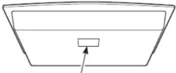
natural_image
Simple line drawing of a rectangular container with an arrow pointing to the bottom (no text or symbols)Name plate location
PRE-INSTALLATION CHECKLIST
BEFORE YOU BEGIN
WARNING
The electrical power to the cooktop supply line must be shut off while connections are being made. Failure to do so could result in serious injury or death.

When preparing the cooktop opening, make sure the inside of the cabinet and the cooktop do not interfere with each other. (See section on preparing the opening.)

Remove packaging materials and literature package from the cooktop before beginning installation.

Be sure to place all literature, Owner's Manual, Installations Instructions, etc. in a safe place for future reference.

Make sure you have all the tools and materials you need before starting the installation of the cooktop.

Your home must provide the adequate electrical service needed to safely and properly use your cooktop. (Refer to section on electrical requirements.)

When installing your cooktop in your home, make sure all local codes and ordinances are followed exactly as stated.

Make sure the wall coverings, countertop and cabinets around the cooktop can withstand heat (up to 200°F) generated by the cooktop.

Installing cooktop in combination with other products. Both products must be installed according to their specific product installation instructions. Consideration must be given to the separate electrical requirements and locations:
Over one or two wall ovens:
- Only certain models may be installed over wall ovens. The wall oven and cooktop will both have a label stating which models are approved in combination.
PREPARING THE OPENING
1 APPROXIMATE COOKTOP DIMENSIONS
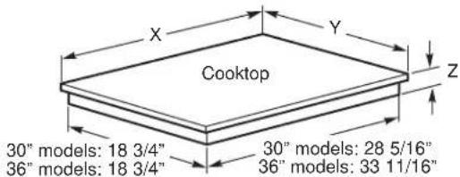
text_image
Cooktop 30" models: 18 3/4" 36" models: 18 3/4" 30" models: 28 5/16" 36" models: 33 11/16"| Size | Models | X | Y | Z | Front | Z | Rear* | |||||
| 30" | PHP6030 | 30 | 11/16" | 21 | 7/16" | 2 | 1 | 8" | 3 | 1/2" | ||
| 36" | PHP6036 | 36 | 5/8" | 21 | 7/16" | 2 | 1/8" | 3 | 1/2" |
* Depth at rear of cooktop at conduit location.
2 CUTOUT DIMENSIONS OF THE COUNTERTOP
To ensure accuracy, it is best to make a template when cutting the opening in the counter.
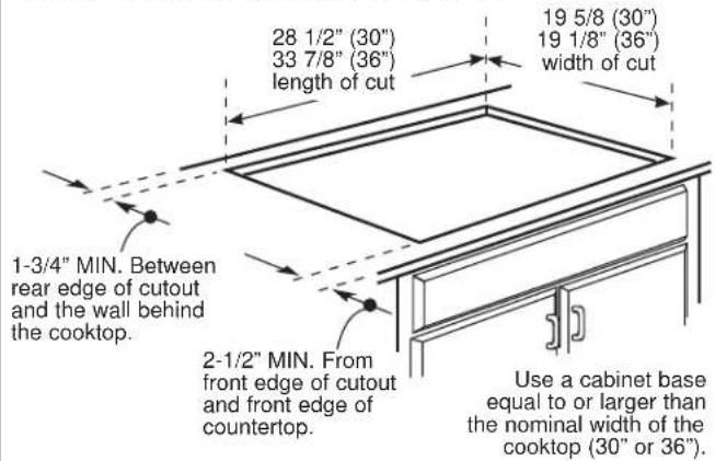
text_image
28 1/2" (30") 33 7/8" (36") length of cut 19 5/8 (30") 19 1/8" (36") width of cut 1-3/4" MIN. Between rear edge of cutout and the wall behind the cooktop. 2-1/2" MIN. From front edge of cutout and front edge of countertop. Use a cabinet base equal to or larger than the nominal width of the cooktop (30" or 36").3 The following MINIMUM clearance dimensions must be maintained.
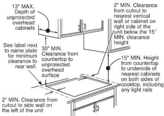
text_image
13" MAX. Depth of unprotected overhead cabinets See label next to name plate for minimum clearance to rear wall. 30" MIN. Clearance from countertop to unprotected overhead surface 2" MIN. Clearance from cutout to side wall on the left of the unit 2" MIN. Clearance from countertop to side wall on the left of the unit 2" MIN. Clearance from cutout to nearest vertical wall or cabinet on right side of the unit below the 15" MIN. clearance height 15" MIN. Height from countertop to underside of nearest cabinets on both sides of cooktop, including any light railsIf a 30" clearance between the cooking surface and overhead combustible materials or metal cabinets cannot be maintained, a minimum clearance of 24" is required and the underside of the cabinets above the cooktop must be protected with not less than 1/4" insulating millboard covered with sheet metal not less than 30 gage (0.0125") thick. A ventilation hood may be installed above the cooktop. See the ventilation hood installation instructions for the appropriate dimensions and clearances.
4 Make sure the wall coverings, countertop and cabinets around the cooktop can withstand heat (up to 200°F) generated by the cooktop.
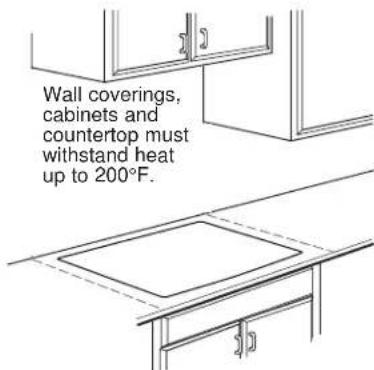
text_image
Wall coverings, cabinets and countertop must withstand heat up to 200°F.PREPARING THE OPENING (Cont)
5 VERTICAL CLEARANCES
Allow 3" minimum vertical clearance for air space from the cooktop bottom (or 6 1/2" minimum depth from the countertop) to any combustible surfaces, such as the top of a cabinet drawer.
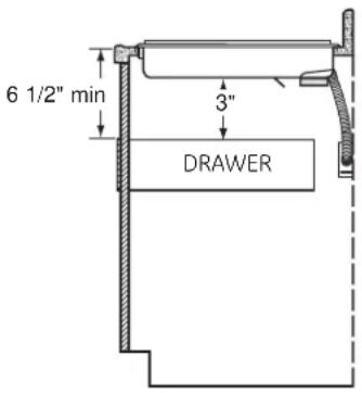
text_image
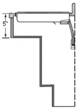
6 1/2" min 3" DRAWER6 FOR AMERICANS WITH DISABILITIES ACT (ADA) FORWARD APPROACH INSTALLATION ONLY
Allow 5" minimum depth between the countertop and an enclosure.
NOTE: The enclosure must be made of at least 1/4" wood material. Also, an access panel is required for the junction box, hold-down brackets, and service.
natural_image
Technical line drawing of a mechanical bracket or support structure with no visible text or symbolsINSTALLING THE COOKTOP
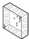
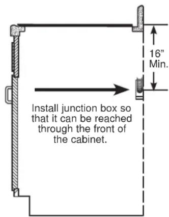
1 INSTALLING THE JUNCTION BOX
Install an approved junction box where it will be easily reached through the front of the cabinet where the cooktop will be located. The cooktop conduit is 4 feet long.
WARNING
The
junction box must be located where it will allow considerable slack in the conduit for serviceability.
text_image
16" Min. Install junction box so that it can be reached through the front of the cabinet.2 PROTECT SURFACE OF COOKTOP
Place a towel or tablecloth onto the countertop. Lay the cooktop upside down onto the protected surface.
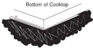
text_image
Bottom of CooktopCloth under Cooktop
NOTE FOR INSTALLING ABOVE A WALL OVEN:
The wall oven will need to be removed during the cooktop installation and then re-installed into its space.
IMPORTANT: Maintain a minimum distance of 31-1/4" from the top surface of the countertop to the wall oven platform to ensure that the cooktop and wall oven do not interfere with each other (see picture).
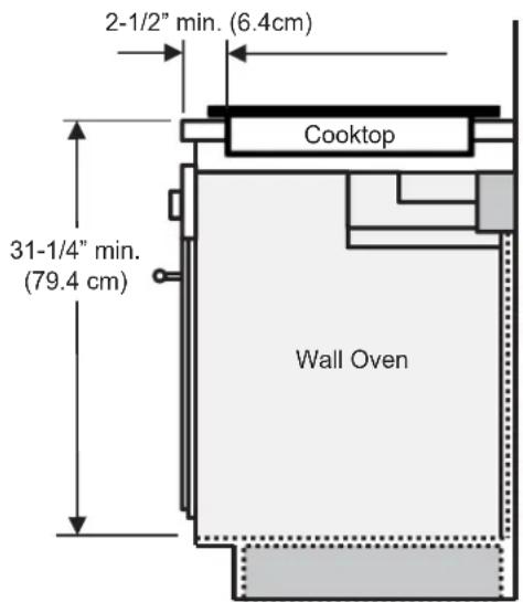
text_image
2-1/2" min. (6.4cm) Cooktop 31-1/4" min. (79.4 cm) Wall OvenSIDE VIEW
3 INSERT COOKTOP INTO CUTOUT
Insert the cooktop centered into the cutout opening. Make sure the front edge of the countertop is parallel to the cooktop. Make final check that all required clearances are met.
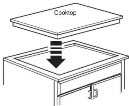
text_image
CooktopELECTRICAL CONNECTIONS

When making the wire connections, use the entire length of conduit provided. The conduit must not be shortened.

With the cooktop in place, open the front of the cabinet door.

Insert the wires from the conduit through the opening of the junction box.
The conduit strain relief clamp must be securely attached to the junction box and the flexible conduit must be securely attached to the clamp.
WARNING
Installations with Aluminum
House Wiring require attention. See Warning under NOTES: ALUMINUM WIRING on page 2.
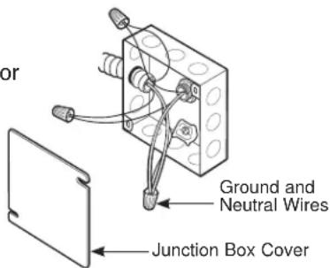
THREE-CONDUCTOR BRANCH CIRCUIT CONNECTION
When connecting to a three-conductor branch circuit, if local codes permit:

Connect the cooktop green ground con duc tor lead to the branch circuit ground (green) using a wire nut.

Connect the cooktop red lead to the branch circuit red lead in using a wire nut.

Connect the cooktop black lead to the branch circuit black lead in ac cor dance with local codes, using a wire nut. If the residence red, black or white leads are aluminum conductors, see WARNING.

Install Junction Box Cover.
text_image
or Ground and Neutral Wires Junction Box CoverNEW CONSTRUCTION AND BRANCH CIRCUIT CONNECTION
- When installing in new construction, or
- When installing in a mobile home, or
- When installing in a recreational vehicle, or
- When local codes do not permit grounding through neutral:

Attach the appliance grounding lead (green or bare copper) in accordance with local codes. If the residence grounding conductor is aluminum, see WARNING.
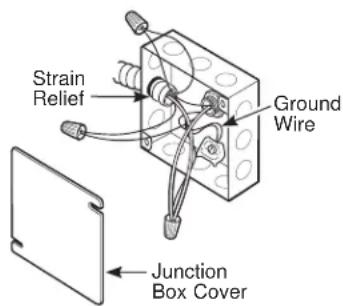
text_image
Strain Relief Ground Wire Junction Box Cover
Connect the red and black leads from the cooktop conduit to the corresponding leads in the junction box.
Connect the ground wire.
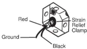
text_image
Red Ground Black Strain Relief Clamp
Once the connections are made, secure wires together using wire nuts.

Install Junction Box Cover.
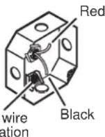
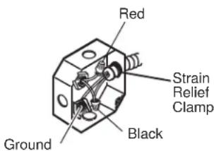
text_image
Red Strain Relief Clamp Black GroundCHECKLISTS
1 PRE-TEST CHECKLIST
A Remove all protective film, if present, and any stickers.
B Check to be sure that all wiring is secure and not pinched or in contact with moving parts.
C Check level of appliance.
D Check that the cooktop is properly grounded.
A Remove all items from the top of the cooktop surface.
B Turn on the power to the cooktop. (Refer to your Owner's Manual.) Verify that all surface burners operate properly.
C Check that the circuit breaker is not tripped nor the house fuse blown.
D Check that conduit is securely connected to the junction box.
LES INSTALLATIONS AVEC
CÂBLAGE DOMESTIQUE EN ALUMINIUM NÉCESSITENT UNE ATTENTION PARTICULIÈRE :
natural_image
Technical line drawing of a mechanical bracket or stair mechanism (no text or symbols)INSTALLATION DE LA TABLE DE CUISSON
1 INSTALLATION DE LA BOÎTE DE JONCTION
National Fire Protection Association
Batterymarch Park
Quincy, MA 02269