LSG202M - Pump Liberty Pumps - Free user manual and instructions
Find the device manual for free LSG202M Liberty Pumps in PDF.


| Brand | Liberty Pumps |
| Model | LSG202M |
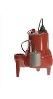
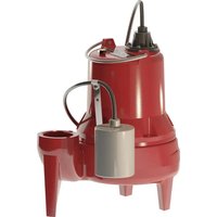
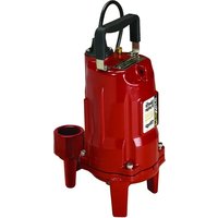
| Pump Type | Submersible sewage grinder pump |
| Power | 2 HP (1.5 kW) |
| Supply Voltage | 208/230 V single-phase |
| Max Current | 15 A |
| Discharge Diameter | 1.25 in FNPT |
| Control Type | Manual (requires external control panel) |
| Thermal Protection | Automatic reset thermal protection device |
| Lower Shaft Seal | Viton lip seal |
| Upper Shaft Seal | Dual face silicon carbide mechanical seal |
| Main Material | Cast iron |
| Max Liquid Temperature | 60 °C (140 °F) |
| Lubrication | ISO-32 turbine oil (3 L capacity) |
| Approximate Weight | 27 kg |
| Warranty | 2-year limited |
| Standards | Compliant with National Electrical Code, Uniform Plumbing Code, International Plumbing Code |
| Usage | Sewage lifting and grinding (do not use for flammable or corrosive liquids) |
| Installation | Guide rail or free-standing in a sump tank |
| Periodic Maintenance | Check rotor rotation, clean housing, start manually once a month if unused |
| Accessories | Requires external control panel (not included) |
Frequently Asked Questions - LSG202M Liberty Pumps
User questions about LSG202M Liberty Pumps
0 question about this device. Answer the ones you know or ask your own.
Ask a new question about this device
Download the instructions for your Pump in PDF format for free! Find your manual LSG202M - Liberty Pumps and take your electronic device back in hand. On this page are published all the documents necessary for the use of your device. LSG202M by Liberty Pumps.
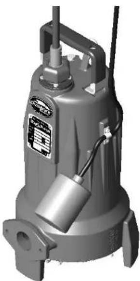
USER MANUAL LSG202M Liberty Pumps
Omnivore® Sewage and Grinder Pumps
Models:
| LSG202A | 2 hp, 208/230V, 1 phase, Automatic |
| LSG202M | 2 hp, 208/230V, 1 phase, Manual |
| LSG202M-C | 2 hp, 208/230V, 1 phase, Manual, external caps |
| LSG203M | 2 hp, 208/230V, 3 phase, Manual |
| LSG204M | 2 hp, 460V, 3 phase, Manual |
| LSG205M | 2 hp, 575V, 3 phase, Manual |
| LSGX202A | 2 hp, 2-Stage, 208-230V, 1 phase, Automatic |
| LSGX202M | 2 hp, 2-Stage, 208-230V, 1 phase, Manual |
| LSGX202M-C | 2 hp, 2-Stage, 208-230V, 1 phase, Manual, external caps |
| LSGX203M | 2 hp, 2-Stage, 208/230V, 3 phase, Manual |
| LSGX204M | 2 hp, 2-Stage, 460V, 3 phase, Manual |
| LSGX205M | 2 hp, 2-Stage, 575V, 3 phase, Manual |
| *Do not throw away or lose this manual. | |
natural_image
3D rendering of a gray industrial water pump with attached control panel and side-mounted valve (no visible text or symbols)Contents
- General Information
- Introduction
- Mechanical Installation
• Electrical Connection - Operation
- Warranty
LibertyPumps®
7000 Apple Tree Avenue
Bergen, NY 14416
Phone: (800) 543-2550
Fax: (585) 494-1839
www.libertypumps.com


IMPORTANT:
Prior to installation, record Model, Serial Number, and Code Number from pump nameplate for future reference.
MODEL ____
SERIAL
CODE
INSTALLATION DATE
Table of Contents
SECTION 1 GENERAL INFORMATION----3
SECTION 2 INTRODUCTION 4
SECTION 3 MECHANICAL INSTALLATION 4-6
SECTION 4 ELECTRICAL CONNECTION 6-8
TROUBLESHOOTING CHART 10
PANEL INSTALLATION SHEET----11
TYPICAL INSTALLATION DRAWING----12
PERFORMANCE CURVE---- 13
SECTION 6 WARRANTY----14
1. General Information
Before installation, read the following instructions carefully. Each Liberty pump is individually factory tested to insure proper performance. Closely following these instructions will eliminate potential operating problems, assuring years of trouble-free service.
WARNING
- Risk of electric shock. Always disconnect the pump from the power source before handling or making adjustments.
- The electrical connections and wiring for a pump installation should only be made by qualified personnel.
- This pump is supplied with a grounding conductor and grounding-type attachment plug. To reduce the risk of electric shock, be certain that it is connected only to a properly grounded, grounding-type receptacle.
- DO NOT bypass grounding wires or remove ground prong from attachment plugs.
• DO NOT use an extension cord. - This pump requires a separate, properly fused and grounded branch circuit. Make sure the power source is properly sized for the voltage and amperage requirements of the pump, as noted on the nameplate.
- The electrical outlet shall be within the length limitations of the pump power cord, and at least 4 feet above floor level to minimize possible hazards from flood conditions.
- The installation must be in accordance with the National Electric Code, Uniform Plumbing Code, International Plumbing Code, as well as all applicable local codes and ordinances.
- Sump and sewage pumps often handle materials which could cause illness or disease. Wear adequate protective clothing when working on a used pump or piping.
- Never enter a pump basin after it has been used. Sewage and effluent can emit several gases which are poisonous.
- Keep clear of suction and discharge openings. To prevent injury, never insert fingers into pump while it is plugged in.
- DO NOT use this product for flammable or corrosive liquid.
- DO NOT use this product in applications where human contact with the pumped fluid is common (such as swimming pools, fountains, etc.)
- NEVER dispose of materials such as paint thinner or other chemicals down drains, as they can chemically attack and damage pump components, potentially causing product malfunction or failure.
CAUTION
- Do not use these pumps in water over 140^ .
- The Uniform Plumbing Code (UPC) states that sewage systems shall have an audio and visual alarm that signals a malfunction of the system, to reduce the potential for property damage.
| Model | HP | Volts | Phase | Full Load Amps | FNPT Discharge | Automatic or Manual* |
| LSG202A | 2 | 208/230 | 1 | 15 | 1.25" | Automatic |
| LSG202M | 2 | 208/230 | 1 | 15 | 1.25" | Manual |
| LSG202M-C | 2 | 208/230 | 1 | 15 | 1.25" | Manual |
| LSG203M | 2 | 208/230 | 3 | 10.6 | 1.25" | Manual |
| LSG204M | 2 | 440/460 | 3 | 5.3 | 1.25" | Manual |
| LSG205M | 2 | 575 | 3 | 4.9 | 1.25" | Manual |
| LSGX202A | 2 | 208-230 | 1 | 15 | 1.25" | Automatic |
| LSGX202M | 2 | 208-230 | 1 | 15 | 1.25" | Manual |
| LSGX202M-C | 2 | 208-230 | 1 | 15 | 1.25" | Manual |
| LSGX203M | 2 | 208/230 | 3 | 10.6 | 1.25" | Manual |
| LSGX204M | 2 | 440/460 | 3 | 5.3 | 1.25" | Manual |
| LSGX205M | 2 | 575 | 3 | 4.9 | 1.25" | Manual |
* Note: Manual models ("M" suffix), require a separate approved pump control device or panel for automatic operation. Operation of these models will be according to the control selected. Make sure the electrical specifications of the control selected properly match the electrical specifications of the pump. Always refer to control panel instructions for proper installation.
Model ("M-C" suffix) require external capacitors and relay.
(Order kit K001316)
start cap - 200-240, 220V
or 216-259 uf, 250V
run cap - 50 uf, 370V
Mars Potential Relay 19551 (#551)
pick up 244V - 270V
drop out of 40V-90V
2. Introduction
2-1 INTRODUCTION
This manual was prepared to assist you in the correct installation, operation, and maintenance of your Liberty pump. Please read it completely before installing the pump. Make certain that you are familiar with the contents, and the chapters on installation and operation are fully understood before running the pump.
Liberty Pumps are designed for minimal maintenance. However, regular checks will ensure longer life and greater operating reliability.
WARRANTY: No repair work should be carried out during the warranty period without prior factory approval. To do so may render the warranty void.
SERIAL #: In all correspondence and reports, make certain that the pump serial number is given.
2-2.1 DESIGN OF PUMP
WARNING
The grinder pump contains metal parts that rotate at high speeds. Be careful around pump base while power is connected. Make sure that the pump is either in the tank or clear from people and wires when in operation.
- Liberty LSG and LSGX-Series grinder pumps are designed for continuous underwater operation. The motor and pump form a close coupled, watertight unit. The induction motor is insulated against heat and moisture in accordance with Class B 265F (130C) regulations.
- A thermal overload protector is imbedded in the stator windings. This is connected in series and wired to shut down the pump if overheating occurs. The overload switch resets automatically when the motor cools.
- The motor is protected against damage from water entry by two seals. The lower seal is a Viton lip seal. The upper seal is mechanical, consisting of two silicon-carbide faces.
- The impeller and volute are designed for efficient flow characteristics and clog-free operation. The hardened cutters grind solids and fibrous matter into small particles that can be safely pumped through small diameter piping.
- For sewage systems, consult local plumbing codes on requirements of venting the tank. The pump shall not be installed in locations classified as hazardous in accordance with the National Electrical Code, ANSI/ NFPA70.
NOTE: The major material of Liberty LSG and LSGX-Series pumps is cast iron. They should not be used to pump corrosive liquids.
3. Mechanical Installation
3-1 INSPECTION UPON RECEIPT
The shipping container should be immediately inspected for damage that may have occurred in shipment. Exercise care in opening the shipping container to avoid damage to the pump. Remove any blocking and cushioning from within the container.
Check all cushioning for spare parts before discarding. Visually check the pump and any spare parts for damage. Check for damaged electrical wires, especially where they exit the motor housing. Contact the Liberty Pumps Customer Service Department to report any damage or shortage of parts. Turn the hex socket head cap screw at the center of the cutter wheel on the bottom of the grinder several rotations clockwise. This will insure that the impeller and cutter are free of any seizure due to prolonged storage. If the impeller is not rotated manually prior to installation, the pump may fail to activate. If the impeller's rotation is difficult or completely resistant, contact the Liberty Pumps Customer Service Department.
3-2 STORAGE BEFORE USE
Liberty pumps are shipped from the factory ready for installation and use. They should be held in storage if the pump station is not complete. If storage is necessary, the pump should remain in its shipping container. It should be stored in a warehouse or storage shed that has a clean, dry temperature-stable area where the pump and its container should be covered to protect it from water, dirt, dust, etc. The ends of the cables - (plugs) must be protected against moisture.
CAUTION
AT NO TIME SHOULD THE PUMP BE STORED WITHIN AN INCOMPLETE WET PIT. THE PUMP SHOULD NOT BE PLACED INTO THE PIT UNTIL IT CAN BE FULLY OPERATED.
LONG TERM STORAGE
-
If it is necessary to store a pump for a long period of time, it should be stored indoors in a clean, dry temperature-stable environment. The pump should be covered to protect it from dust, dirt and water. The plug end of the cable must be protected against moisture.
-
Do not allow the pump to freeze.
-
Prior to installation, the pump motor should be rotated to ensure the seals and cutters are free spinning.
-
Installed pumps which are idle for long periods of time should be manually operated through the breaker panel once a month to lubricate the seals. Turn off the breaker, unplug the piggyback switch, and plug the pump directly into the wall socket. Turn the breaker on for 30 seconds. Turn the breaker off, and then plug the piggyback switch back in. (refer to Section 4-1)
3-3 PUMP INSTALLATION
WARNING
THIS PUMP IS NOT TO BE INSTALLED IN LOCATIONS CLASSIFIED AS HAZARDOUS IN ACCORDANCE WITH THE NATIONAL ELECTRICAL CODE, ANSI/NFPA 70.
- Grinder pumps must be installed in a tank that is vented in accordance with local plumbing codes. Installation should be at a sufficient depth to ensure that all plumbing is below the frost line. If this is not feasible, remove the check valve and size the basin and/or adjust pump differential to accommodate the additional backflow volume. Consult the factory for details on how this should be done.
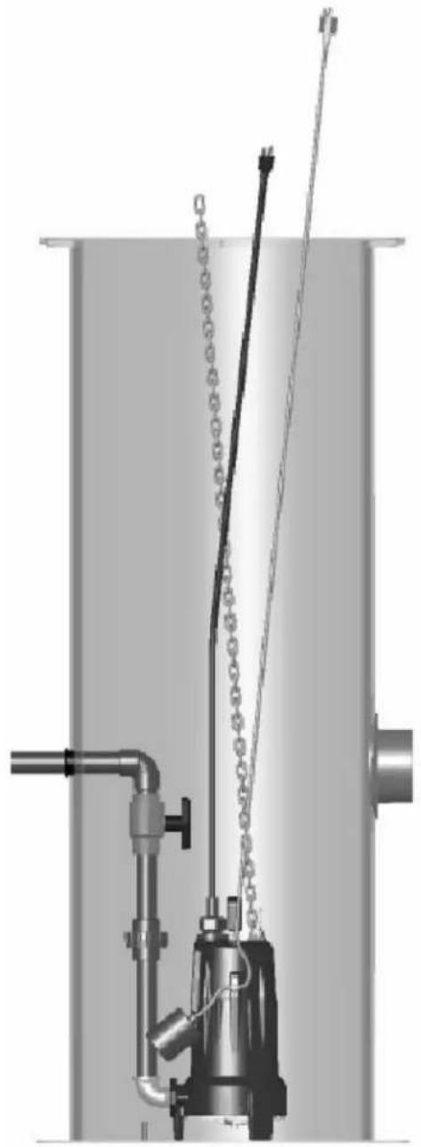
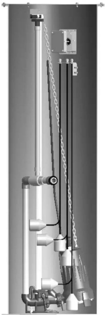
The Omnivore Grinders may be guide rail mounted using Liberty's GR20 guide rail base, or stand-alone. (See Figure 3, page 11) They may be installed as a completely packaged simplex (single pump) or duplex (two-pump) system. Installation of the pump shall be in accordance with state and local codes and performed only by qualified personnel. Typical installations consist of a guide rail mount in a fiberglass, concrete or polyethylene tank. This section assumes guide rail installation.
CAUTION
-
Liberty GR20 Guide Rail systems feature a self-aligning mounting bracket. Using the lifting chain, slip the pump bracket over the upper guide rail bracket. Lower the pump at an angle down the guide rail into the tank. (See Figure 3, page 11)
-
As the pump nears its final position, the straightening rib squares the pump bracket with the guide bracket ears. When the pump bracket ears hook the guide bracket ears, the chain will slacken.
-
Grasp the lifting chain and shake the pump to ensure a good seat with the gasket. The pump is suspended by the bracket ears. The weight of the pump compresses the gasket against the mating flange of the guide bracket base.
-
The lifting chain may be removed from the hoist and hooked near the upper guide rail bracket.
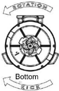
IMPORTANT: For 3-phase pumps, check for proper rotation before installing pump into basin. See figure A for proper rotation.
Fig. A – Proper impeller rotation, three phase models
text_image
ROTATION Bottom KICKCheck three phase pumps for proper rotation prior to installing pump(s) in basin. To change rotation, reverse any two of the three power leads to the pump. Code the wires for reconnection after installation.
4. Electrical Connection
AFTER THE PUMP IS INSTALLED, THE ELECTRICAL CHECKS OF SECTION 4 MUST BE PERFORMED.
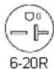
- Plug the Piggyback switch into a 6-20R receptacle. The receptacle must be wired to a 30-amp breaker. Be sure to have the breaker turned off before plugging in the switch.
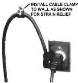
- Plug the pump power cord into the piggyback switch as shown.
- The pump is ready to test and your breaker can be turned on.
(Refer to section 5)
text_image
INSTALL CABLE CLAMP TO WALL AS SHOWN FOR STRAIN RELIEFALWAYS TURN OFF BREAKERS BEFORE WORKING ON ELECTRICAL CORDS. BE CAREFUL NOT TO DRILL OR SCREW INTO EXISTING WIRING.
PIGGY BACK PLUG INSTALLATION
text_image
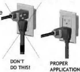
e DON'T DO THIS! PROPER APPLICATION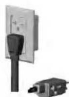

TEMPORARY, MANUAL OPERATION
ENSURE THAT POWER IS OFF AT BREAKER BEFORE PLUGGING OR UNPLUGGING!
Check to make sure installation is in accordance with the National Electric Code and all applicable local codes. Installation and servicing is to be conducted by qualified personnel. This pump is supplied with a grounding conductor. To reduce the risk of electrical shock, be certain that it is connected to a properly grounded earth wire.
4-2 DIRECT WIRING OF AUTOMATIC PUMP
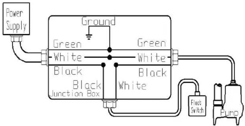
The pump can run on a voltage rating of 230V or 208V. Check that it is the same as the supply voltage. The pumps are supplied with 6-20P (20-amp) cord plug ends. If a single phase pump is to be wired directly into a control device or junction box, and it is necessary to remove the plugs, have a certified electrician do the wiring in accordance with the National Electric Code and applicable local codes. See Fig. B for direct wire installation of single phase, automatic pumps.
- The control panel is preferably mounted in a cool, dry environment. Installation and connections are specific to the control panel. Control panels should be installed and serviced only by a qualified electrician (Refer to Figure 2, page 10).
flowchart
graph TD
    A["Power Supply"] --> B["Ground"]
    B --> C["Green White"]
    B --> D["Black Junction Box"]
    C --> E["Green White"]
    C --> F["Black White"]
    D --> G["Black Junction Box"]
    E --> H["Float Switch"]
    F --> I["Pump"]
Fig. B – Direct Wiring of 120V or 208-230V Single Phase, Automatic Pumps
REFER TO WIRING DIAGRAM INCLUDED WITH CONTROL PANEL. IF THERE IS NO WIRING DIAGRAM, CONTACT THE MANUFACTURER TO OBTAIN ONE. DO NOT ATTEMPT TO CONNECT PUMP WITHOUT A WIRING DIAGRAM.
4-4 EXTERNAL CAPACITORS
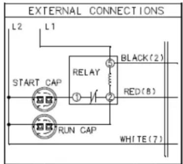
The LSG202M-C and LSGX202M-C (208-230V SINGLE PHASE UNITS) are designed such that the capacitors and start relay are mounted in a control panel external from the pump. The most basic wiring diagram is illustrated in Figure C. Increased functionality of the panel like simplex or duplex pump control would complicate the wire schematic. Before connecting the pump consult the schematic for the specific panel or contact the panel manufacturer.
| Component specifications: start cap - 200-240 uf, 220V or 216 – 259 uf, 250V run cap - 50 uf, 370V Mars Potential Relay 19551 (#551) pick up 244V – 270V drop out of 40-90V (Available in Start Kit K001316) |
text_image
EXTERNAL CONNECTIONS L2 L1 START CAP RELAY BLACK(2) ① ② RED(8) RUN CAP WHITE(7)Figure C
4-5 STEPS TO BE TAKEN BEFORE ENERGIZING
- Retighten all field-made connections. Retighten all factory-made connections. These may have loosened due to shipping and handling vibrations.
- Check the security of mounting hardware.
- Check the enclosure to see that it has not been damaged in such a manner as to reduce electrical spacing.
- Rotate the cutter wheel with the hex socket head cap screw to verify movement and lubricate the seals.
- Ensure that no wires or other obstacles are in the way of the pump cutter.
- Conduct an electrical insulation resistance test to make sure that the control panel is free from short circuits and ground faults. This should be done both phase-to-phase and phase-to-ground.
- MOTOR OVERLOAD PROTECTION: The pump motor is protected from locked rotor and running overloads by a thermal overload integrally mounted to the motor (Single Phase Only). No adjustments are required.
- Check to determine that all grounding connections are made properly
- If a panel is used, remove all debris, scrap wire, etc., from the control panel interior before closing the doors. Install covers, close doors making certain that no wires are pinched and that all enclosure parts are properly aligned and tightened.
WARNING
ENERGIZING THE CONTROL PANEL OR BREAKER FOR THE FIRST TIME IS POTENTIALLY DANGEROUS. LICENSED ELECTRICAL PERSONNEL SHOULD BE PRESENT WHEN THE PANEL OR BREAKER IS ENERGIZED FOR THE FIRST TIME. IF FAULTS CAUSED BY DAMAGE OR POOR INSTALLATION PRACTICES HAVE NOT BEEN DETECTED, SERIOUS DAMAGE CAN RESULT WHEN POWER IS APPLIED (REFER TO SECTION 5).
4-6 FLOAT SWITCHES
- The pump's on and off cycles are normally controlled by a "piggy back" float switch attached to the side of the pump, or by hanging switches in the wet well. Refer to panel or switch instructions for proper electrical connection
4-6.1 FLOAT SEQUENCE- PIGGY BACK (AUTOMATIC MODELS LSG202A & LSGX202A)
-
As the liquid level in the wet well rises, the float tilts, closing the switch. This starts the pump.
-
The pump runs until the liquid level falls below the "PUMP OFF" level of the float (Factory set at 7" minimum), emptying the wet well.
4-6.2 FLOAT SEQUENCE-SIMPLEX (MANUAL MODELS)
-
As the liquid level in the wet well rises, the "PUMP OFF" float tilts, closing the switch (This level must be set at a minimum of 7"). As the liquid level continues to rise, the "PUMP ON" float tilts. This switch closes, starting the pump.
-
The pump runs until the liquid level falls below the "PUMP OFF" float, emptying the wet well.
-
In the event of a malfunctioning float switch, control relay or pump, the liquid level rises and tilts the "HIGH LEVEL ALARM" float. The alarm system will activate.
4-6.3 FLOAT SEQUENCE-DUPLEX (MANUAL MODELS)
-
As the liquid level in the wet well rises, the "PUMP OFF" tilts, closing the switch. As the liquid level continues to rise, the "LEAD PUMP ON" float tilts. This switch closes, starting the lead pump. The pump runs until the liquid level falls below the "PUMP OFF" float, emptying the wet well.
-
On the next rise of the liquid level, the other pump will start on the "LEAD PUMP ON" signal. The pumps will continue to alternate their cycles.
NOTE: The ON/OFF float switch differential should be set as to not exceed 12 starts per hour.
-
If the liquid level rises to the "LAG PUMP ON" float, the second pump will start. Both pumps will run until the liquid falls below the "PUMP OFF" float, emptying the wet well.
-
In the event of a malfunctioning float switch, control relay or pump, the liquid level rises and tilts the "HIGH LEVEL ALARM" float. The alarm system will activate.
4-6.4 FLOAT SWITCH INSTALLATION
The engineering drawings will normally specify the levels for pump start and stop and high level alarm. If they are not specified, these guidelines should be used to determine float switch locations.
PIGGY BACK SWITCH
(1-Float System)
Pump Off: Factory set. (Float tether 4")
Pump On: Factory set. (Float tether 4")
SIMPLEX PUMP STATION
(3-Float System)
Pump Off: Level to top of motor housing.
Pump On: Minimum 1-1/2 ft. above Pump Off Level.
High Level Alarm: Minimum 1 ft. above pump ON level. Below influent pipe.
DUPLEX PUMP STATION
(4-Float System)
Pump Off: Level to top of motor housing.
Lead Pump On: Minimum 1-1/2 ft. above Pump Off level.
Lag Pump On: Minimum 1 ft. above Lead Pump On level.
High Level Alarm: Minimum 1 ft. above Lag Pump On level. Below influent pipe.
5. Operation
5-1 OPERATION
After the electrical and mechanical installations have been performed, the pump is ready for operation. No operational procedures are required except to apply rated power to the pump. There are no specific shutdown procedures beyond disconnecting the power supply.
CAUTION
IF THE ROTATION OF A SINGLE PHASE PUMP IS INCORRECT, NOTIFY THE LIBERTY PRODUCT SERVICE DEPARTMENT IMMEDIATELY. DO NOT SWITCH THE POWER SUPPLY LEADS. DO NOT OPERATE THE PUMP.
WARNING
ALWAYS ENSURE THAT THE PUMP IS FREE OF WIRES OR OTHER OBSTRUCTIONS THAT MAY CAUSE HARM OR INJURY.
5-2 PERIODIC MAINTENANCE & LUBRICATION
Liberty pumps are designed for long lasting, efficient and reliable service with a minimum of preventive maintenance checks. These checks are few but will add years of satisfactory service to the life of the pump. Maintenance checks should be performed at the intervals stated. Severe operating environments will require more frequent checks.
5-3 LUBRICATION
Pump is permanently lubricated and cooled by turbine oil. If replacement oil is required, use ISO-32 turbine oil. If this is unavailable a full synthetic SAE 5W-30 or 5W-20 motor oil may be used. Capacity .8 gallons.
TROUBLESHOOTING CHART: LSG200
| SYMPTOM | POSSIBLE CAUSE | ACTION |
| 1. PUMP WILL NOT START | A. Power supply failure | A. Check power supplyCheck out electrical system for loose connectionsCheck operating voltage |
| B. Burned out fuse or tripped circuit breaker | B. Check circuit protectors | |
| C. Damaged power cable | C. Check external cable for damage - repair | |
| D. Jammed impeller | D. Inspect and remove jamming object | |
| E. Water inside motor | E. Refer to Symptom 5 and 6 | |
| 2. REPEATED TRIPPING | A. Circuit protection under-rated | A. Check rating and replace with proper size |
| B. Current unbalance | B. Check current draw | |
| C. Pump connected to incorrect voltage | C. Verify connections. See wiring diagram | |
| D. Wet or damaged wiring | D. Inspect external cable, replace if worn or damaged | |
| E. Obstruction in pump | E. Remove obstruction | |
| F. Incorrect motor rotation | F. Check rotation | |
| G. Foreign matter build-up | ||
| 3. PUMP WILL NOT SHUT OFF | A. Control panel failure | A. Clean motor housing |
| B. Switch Failure | B. Check control panel | |
| C. B. Replace the switch | ||
| 4. LOW FLOW | A. Incorrect pump rotation | A. Check rotation |
| B. Low liquid level | B. Check liquid level | |
| C. Obstruction in pump or piping | C. Remove obstruction | |
| D. Partially closed valve(s) | D. Check and adjust valve | |
| 5. WATER IN OIL CHAMBER | A. Loose or damaged oil plug | A. Check plug and sealing washer |
| 6. WATER INSIDE MOTOR CASING | A. Damaged lower lip seal or mechanical seal | A. Replace seal |
| B. Damaged O-Ring between oil chamber and motor plate | B. Replace O-Ring | |
| C. Damaged cable | C. Replace cable |
IF SYMPTOMS CONTINUE, CONSULT THE LIBERTY PUMPS PRODUCT SERVICE DEPT.
CONTROL PANEL INSTALLATION INSTRUCTIONS
WARNING

natural_image
Silhouette of a hand with a lightning bolt symbol and a warning symbol (no text or numbers present)ELECTRICAL SHOCK HAZARD
Disconnect all power sources before servicing. Failure to do so could result in serious injury or death.
This control panel must be installed by a LICENSED ELECTRICIAN and in accordance with the National Electric Code NFPA-70, and state and local codes.
All conduit running from the sump or tank to the control panel must be sealed with conduit sealant to prevent moisture or gases from entering the control panel. NEMA 1 enclosures are for indoor use primarily to provide a degree of protection against contact with enclosed equipment. Cable connectors are not required to be liquid tight on NEMA 1 enclosures. Do not use NEMA 1 enclosures if subjected to rain, splashing water, or hose-directed water. NEMA 4X enclosures are for indoor or outdoor use primarily to provide a degree of protection against corrosion, windblown dust and rain, splashing water, and hose-directed water. Cable and conduit connectors must be liquid tight on NEMA 4X enclosures.
Mounting and Wiring the Control Panel
- Determine the mounting location for the control panel. If distance exceeds the length of either the control switch cables or the pump power cables, splicing will be required. For an outdoor or a wet installation we recommend the use of a junction box with liquid tight connectors to make required connections. You must use conduit sealant to prevent moisture or gases from entering the panel.
- Mount the control panel (mounting devices are furnished with control panel).
- Determine the conduit entrance locations on the control panel. Check local codes and schematic for power circuit requirements.
CAUTION: BE SURE THE POWER SUPPLY VOLTAGE AND PHASE ARE THE SAME AS THE PUMP MOTORS BEING INSTALLED. IF IN DOUBT, SEE THE PUMP IDENTIFICATION PLATE FOR VOLTAGE/PHASE REQUIREMENTS. - Drill proper size holes for connection to the panel. CAUTION: IF USING CONDUIT, BE SURE THAT THE CONDUIT BEING USED IS OF ADEQUATE SIZE TO PULL THE PUMP AND SWITCH CABLES THROUGH. RECOMMENDED MINIMUM 1 1/2" FOR DUPLEX APPLICATIONS.
- Attach cable connectors and/or conduit connectors to the control panel. CAUTION: AT THIS POINT, TURN OFF ALL POWER SOURCES.
FOR INSTALLATIONS WITHOUT A SPLICE, GO TO STEP 11.
FOR INSTALLATIONS REQUIRING A SPLICE, FOLLOW STEPS 6-10.
- Determine the location for mounting the junction box according to local code requirements. Do not mount the junction box inside the sump or basin.
- Run the conduit or connectors to junction box and drill the junction box as required to make the proper connections. Attach the conduit or connectors to the junction box.
- Mount junction box to proper support.
- Identify and label each wire before pulling through conduit into junction box. Make necessary wire splice connections at the junction box.
- Firmly tighten all fittings on the junction box.
- Pull pump cables and control switch cables through connectors/conduit into the control panel.
- Connect pump cables and control switch cables to the appropriate terminals. SEE SCHEMATIC INSIDE CONTROL PANEL.
CAUTION: IF CONTROL SWITCH CABLES ARE NOT WIRED IN THE CORRECT ORDER, THE PUMP SYSTEM WILL NOT FUNCTION PROPERLY.
- Connect "power in" conductors to proper terminals. SEE SCHEMATIC.
- Verify the correct operation of the control panel after installation is complete.
©SJE-Rhombus
1005370C
9/00
FIGURE 3 TYPICAL INSTALLATION
natural_image
Industrial equipment setup with pipes, chains, and a vertical cylindrical tank (no visible text or symbols)WITHOUT GUIDE RAIL

natural_image
Industrial piping system with mechanical components and chains (no visible text or symbols)WITH GR20 GUIDE RAIL
PERFORMANCE CURVE
Omnivore Grinders
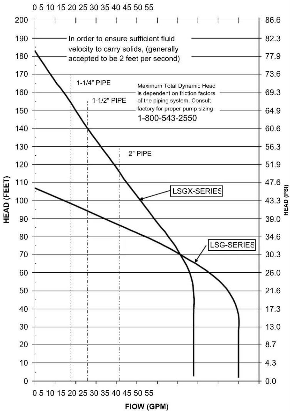
line
| FLOW (GPM) | HEAD (FEET) - 1-1/4" PIPE | HEAD (FEET) - 1-1/2" PIPE | HEAD (PSI) - LSGX-SERIES | HEAD (PSI) - LSG-SERIES | | ---------- | -------------------------- | -------------------------- | -------------------------- | ------------------------ | | 0 | 185 | 108 | 86.6 | 47.6 | | 25 | 150 | 95 | 73.6 | 39.0 | | 50 | 120 | 80 | 69.3 | 30.3 | | 80 | 100 | 70 | 64.9 | 21.6 | | 100 | 80 | 60 | 60.6 | 13.0 | | 120 | 60 | 50 | 56.3 | 4.3 | | 140 | 40 | 40 | 51.9 | 0.0 | | 160 | 20 | 30 | 47.6 | 0.0 | | 180 | 0 | 20 | 43.3 | 0.0 | | 200 | 0 | 10 | 39.0 | 0.0 | | 220 | 0 | 5 | 34.6 | 0.0 | | 240 | 0 | 2 | 30.3 | 0.0 | | 260 | 0 | 1 | 26.0 | 0.0 | | 280 | 0 | 0 | 21.6 | 0.0 | | 300 | 0 | 0 | 17.3 | 0.0 | | 320 | 0 | 0 | 13.0 | 0.0 | | 340 | 0 | 0 | 8.7 | 0.0 | | 360 | 0 | 0 | 4.3 | 0.0 | | 380 | 0 | 0 | 0.0 | 0.0 | | 400 | 0 | 0 | 0.0 | 0.0 | | 420 | 0 | 0 | 0.0 | 0.0 | | 440 | 0 | 0 | 0.0 | 0.0 | | 460 | 0 | 0 | 0.0 | 0.0 | | 480 | 0 | 0 | 0.0 | 0.0 | | 500 | 0 | 0 | 0.0 | 0.0 | | 520 | 0 | 0 | 0.0 | 0.0 | | 540 | 0 | 0 | 0.0 | 0.0 | | 560 | 0 | 0 | 0.0 | 0.0 | | 580 | 0 | 0 | 0.0 | 0.0 | | 600 | 0 | 0 | 0.0 | 0.0 | | 620 | 0 | 0 | 0.0 | 0.0 | | 640 | 0 | 0 | 0.0 | 0.0 | | 660 | 0 | 0 | 0.0 | 0.0 | | 680 | 0 | 0 | 0.0 | 0.0 | | 700 | 0 | 0 | 0.0 | 0.0 | | 720 | 0 | 0 | 0.0 | 0.0 | | 740 | 0 | 0 | 0.0 | 0.0 | | 760 | 0 | 0 | 0.0 | 0.0 | | 780 | 0 | 0 | 0.0 | 0.0 | | 885 | — | — | — | — | | Note: The data is already in CSV format with three columns: "HEAD (FEET)" and "HEAD (PSI)". The numbers in the table represent the names of the pipes and series.6.
2 Year Limited Warranty
Liberty Pumps, Inc. warrants that pumps of its manufacture are free from all factory defects in material and workmanship for a period of 2 years from the date of purchase. The date of purchase shall be determined by a dated sales receipt noting the model and serial number of the pump. The dated sales receipt must accompany the returned pump if the date of return is more than 2 years from the "CODE" (date of manufacture) number noted on the pump nameplate.
The manufacturer's obligation under this Warranty shall be limited to the repair or replacement of any parts found by the manufacturer to be defective, provided the part or assembly is returned freight prepaid to the manufacturer or its authorized service center, and provided that none of the following warranty-voiding characteristics are evident.
The manufacturer shall not be liable under this Warranty if the product has not been properly installed; if it has been disassembled, modified, abused or tampered with; if the electrical cord has been cut, damaged or spliced; if the pump discharge has been reduced in size; if the pump has been used in water temperatures above the advertised rating, or water containing sand, lime, cement, gravel or other abrasives; if the product has been used to pump chemicals or hydrocarbons; if a non-submersible motor has been subjected to excessive moisture; or if the label bearing the serial, model and code number has been removed. Liberty Pumps, Inc. shall not be liable for any loss, damage or expenses resulting from installation or use of its products, or for consequential damages, including costs of removal, reinstallation or transportation.
There is no other express warranty. All implied warranties, including those of merchantability and fitness for a particular purpose, are limited to two years from the date of purchase.
This Warranty contains the exclusive remedy of the purchaser, and, where permitted, liability for consequential or incidental damages under any and all warranties are excluded.
natural_image
3D rendering of a gray industrial water pump with attached control panel and side-mounted sensor (no visible text or symbols)*Ne pas jeter ni perdre ce manuel.
Table des matières
natural_image
Industrial equipment setup with pipes, chains, and a vertical cylindrical tank (no visible text or symbols)SANS RAIL DE GUIDAGE
natural_image
Industrial piping system with vertical and horizontal pipes, no visible text or symbolsAVEC RAIL DE GUIDAGE GR20
COURBES DE RENDEMENT
Pompes omnivores broyeuses
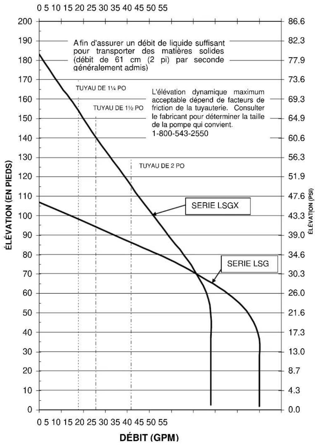
natural_image
Industrial water pump device with attached piping and valve (no visible text or symbols)natural_image
Industrial equipment setup with pipes, chains, and a vertical cylindrical tank (no visible text or symbols)SIN GUIADERA CON GUIADERA GR20