P382XPRG102 - Pump Liberty Pumps - Free user manual and instructions
Find the device manual for free P382XPRG102 Liberty Pumps in PDF.


User questions about P382XPRG102 Liberty Pumps
0 question about this device. Answer the ones you know or ask your own.
Ask a new question about this device
Download the instructions for your Pump in PDF format for free! Find your manual P382XPRG102 - Liberty Pumps and take your electronic device back in hand. On this page are published all the documents necessary for the use of your device. P382XPRG102 by Liberty Pumps.
USER MANUAL P382XPRG102 Liberty Pumps
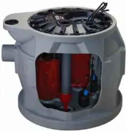
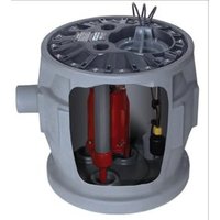
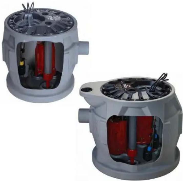
PROVORE® 380 & PROVORE® 680-Series 1 hp. Residential Grinder Systems
Simplex Models
• P382XPRG101 - 1 hp., 115 Volt
• P382XPRG102 - 1 hp., 230 Volt
Duplex Models
Indoor control panel
• P682XPRG101 - 1 hp., 115 Volt
• P682XPRG102 - 1 hp., 230 Volt
Outdoor control panel
• P682XPRG101W - 1 hp., 115 Volt
• P682XPRG102W - 1 hp., 230 Volt
Contents
1.) General Information
2.) The Basin
3.) Installation and Connections
4.) QuickTree® and Access Cover
5.) Electrical Service and Operation
6.) Maintenance and Troubleshooting
Liberty Pumps
7000 Apple Tree Avenue
Bergen, NY 14416
Phone: (800) 543-2550
Fax: (585) 494-1839
www.libertypumps.com
natural_image
Two views of a mechanical device showing internal components and housing (no text or symbols visible)IMPORTANT:
Prior to installation, record Model, Serial Number, and Code Number from pump nameplate for future reference.
MODEL
SERIAL
CODE
INSTALLATION
DATE ____
1. General Information
The ProVore ^® 1 hp. residential grinder system easily handles solids and sewage waste found in typical residential applications. Its unique cutter system grinds difficult wastes and then pumps it through a 1-1/2" or 2" discharge line. The ProVore ^® system is supplied with a 2" discharge outlet. Do not increase this pipe size above 2" as adequate flow rates may not be achieved for proper operation. Discharge sizes may be reduced to 1-1/2" or 1-1/4". Please consult factory for proper pipe and system sizing.
Before installation, read the following instructions carefully. Each Liberty pump is individually factory tested to insure proper performance. Closely following these instructions will eliminate potential operating problems, assuring years of trouble-free service.
WARNING
- Risk of electric shock. To reduce risk of electric shock, always disconnect pump from power source before handling.
• The electrical connections and wiring for a pump installation should only be made by qualified personnel. - This pump is supplied with a grounding conductor or a grounding-type attachment plug. To reduce the risk of electric shock, be certain that the grounding conductor is connected only to a properly grounded control panel or, if equipped with a grounding-type plug, that it is connected to a properly grounded, grounding-type receptacle.
- Do not bypass grounding wires or remove ground prong from attachment plugs.
- Do not remove cord and strain relief, and do not connect conduit to pump.
- Do not use an extension cord.
- This pump requires separate, properly fused and grounded branch circuit. Make sure the power source is properly sized for the voltage and amperage requirements of the motor, as noted on the pump nameplate.
- The electrical outlet or panel shall be within the length limitations of the pump power cord, and at least 4 feet above floor level to minimize possible hazards from flood conditions.
- These pumps are not to be installed in locations classified as hazardous in accordance with the National Electric Code, ANSI/NFPA 70.
• The installation must be in accordance with the National Electric Code and all applicable local codes and ordinances.
CAUTION
- Do not use these pumps in water over 140^ .
- The Uniform Plumbing Code (UPC) states that sewage systems shall have an audio and visual alarm that signals a malfunction of the system, to reduce the potential for property damage.
System: The ProVore® residential grinder system is shipped from the factory fully assembled. The following chart lists the grinder pumps available. Your specific pump is identified by the model number on the nameplate attached to the Pro-Series cover. Pro 380 Systems ordered with alarm option have an "/A" suffix designating the alarm. "/A2" ...ALM-2, "/A2W" ...ALM-2W; all Pro 680 systems come with an integral control system with alarm. Also systems are available with an 8" extension to increase the height of the basin these models are designated with an X8 example: P382X8XPRG101.
| System Model | Pump Model | HP | Volts | Phase | Full Load Amps | FNPT Discharge | Min. Shut-off Head (no-flow) | 10' (3m) Stack Test |
| P382XPRG101 | PRG101M | 1 | 115 | 1 | 12 | 2" | 45' (13.5 M) | YES |
| P382XPRG102 | PRG102M | 1 | 230 | 1 | 6 | 2" | 45' (13.5 M) | YES |
| P682XPRG101 | PRG101M | 1 | 115 | 1 | 12 | 2" | 45' (13.5 M) | YES |
| P682XPRG102 | PRG102M | 1 | 230 | 1 | 6 | 2" | 45' (13.5 M) | YES |
Note: All P380-Simplex and P680-Duplex Systems are shipped standard with 16 cover bolts and pass the 10' Stack Test.
Pump and Alarm floats are pre-set on the QuickTree ^® system at proper operating levels. Do not adjust floats.
Was your system sized by a professional? Minimum fluid flows are required in sewage applications. Consult Factory for proper pump sizing prior to installation.
QuickTree ^® Technology: ProVore ^® P380 and P680 systems by Liberty Pumps features QuickTree ^® float technology. The QuickTree ^® system is located under a separate access cover for ease of maintenance and service. Floats for both pump activation and alarm (if equipped) are mounted on a stainless steel tree (rod), separate from the pump. There is no need to disconnect plumbing or remove the pump to inspect service or replace floats. QuickTree ^® floats are preset at the factory for optimum operating levels and should not be adjusted.
2. The Basin
Provore® P380 and P680 systems feature a clear disposable construction cover designed to protect the system during rough-in and masonry work. The protective cover should remain in place until finish plumbing; however, can be removed and reinstalled if required. The cover is snapped into the threaded ports of the cover. To remove the clear cover, simply pull upward disengaging it from the threaded ports.
In Ground Installation of Pro-Series Basins
A. Excavation: Excavate the hole as small as possible, with a minimum recommended 8" diametrical clearance around the tank. Never place the basin directly in contact with rocks or other sharp objects. Place only fine, 1/8" to 3/4" pea gravel or 1/8" to 1/2" washed, crushed stone as bedding between the basin and the hole walls. Do not use sand or native soil as backfill. Properly compact underneath the basin to provide a solid, level base that can support the weight of the filled basin. It is recommended that the top lip of the basin be level with the finished floor.
B. Initial Backfill: Only fine, 1/8" to 3/4" pea gravel or 1/8" to 1/2" washed, crushed stone should be used around the bottom of the basin to hold it in place. Do not use sand or native soil as backfill. Make the inlet connection as required for your basin.
C. Inlet Connection: The Liberty P380 and P680 series basins have a 4" inlet molded to the side of the tank. This inlet is sized to accept a 4" no-hub type coupling. Connect the gravity drainage line from the fixtures to this hub.
D. Final Backfill: Large rocks, clods, and foreign objects should be kept out of the backfill material. Only fine, 1/4" to 3/4" pea gravel, or 1/8" to 1/2" washed, crushed stone is recommended. Do not use sand or native soil as backfill. Mound the backfill slightly and allow for natural settling. Provide access to the basin cover for maintenance and service.

pressure or run heavy equipment on the backfill material as this could cause the tank to collapse.
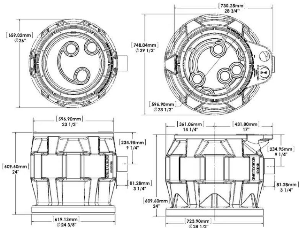
Dimensional Data:
PRO380 Simplex Models
PRO680 Duplex Models
text_image
[659.02mm] Ø26" [748.04mm] Ø29 1/2" [730.25mm] 28 3/4" [596.90mm] Ø23 1/2" [596.90mm] 23 1/2" [361.06mm] 14 1/4" [431.80mm] 17" [234.95mm] 9 1/4" [609.60mm] 24" [81.28mm] 3 1/4" [609.60mm] 24" [723.90mm] Ø28 1/2"©Copyright 2013 Liberty Pumps Inc. All rights reserved
3. Installation and Connections
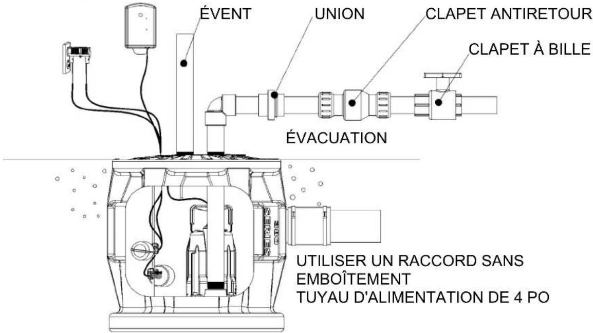
A. Discharge: Using an adapter, connect the discharge pipe to the threaded 2" port provided on the cover. IMPORTANT: NOTE: This ProVore® system is supplied with a 2" discharge outlet. Do not increase the pipe size above 2" as adequate flow rates may not be achieved for proper operation. Discharge sizes may be reduced to 1-1/2" or 1-1/4". Contact Liberty Pumps if you have questions regarding proper pipe sizes and flow rates.
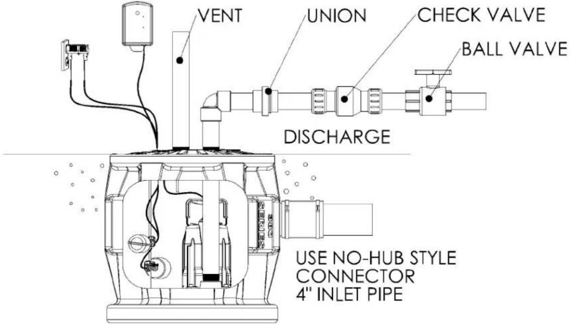
Install the remaining discharge line. A union should be installed just above the cover to facilitate pump removal if necessary. A check valve is recommended after the union to prevent the backflow of liquid after each pumping cycle. A gate or ball valve should follow the check valve to allow periodic cleaning of the check valve or removal of the pump. The remainder of the discharge line should be as short as possible with a minimum number of turns, to minimize friction head loss. Contact Liberty Pumps or other qualified person if there are questions regarding proper pipe size and flow rates.
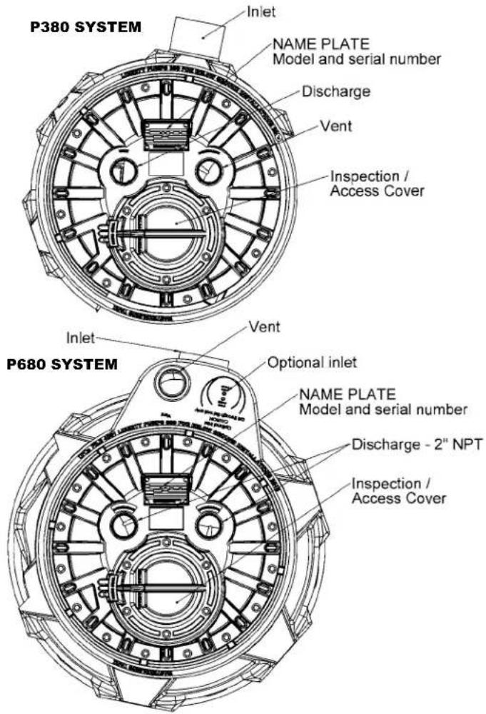
B. Vent: A threaded 2" or 3" connection is provided on top of the cover on a P380 SYSTEM or a 2" or 3" slip type Uni-Seal on a P680 SYSTEM; the vent must be piped to the existing building vent, or extended outside on its own standpipe. The vent size should be in accordance with applicable codes, but not less than the discharge size.
text_image
P380 SYSTEM Inlet NAME PLATE Model and serial number Discharge Vent Inspection / Access Cover P680 SYSTEM Inlet Vent Optional inlet NAME PLATE Model and serial number Discharge - 2" NPT Inspection / Access CoverTypical Installation
This is a recommended installation only. Variations may apply.
ALARM (OPTIONAL)
text_image
VENT UNION CHECK VALVE BALL VALVE DISCHARGE USE NO-HUB STYLE CONNECTOR 4" INLET PIPE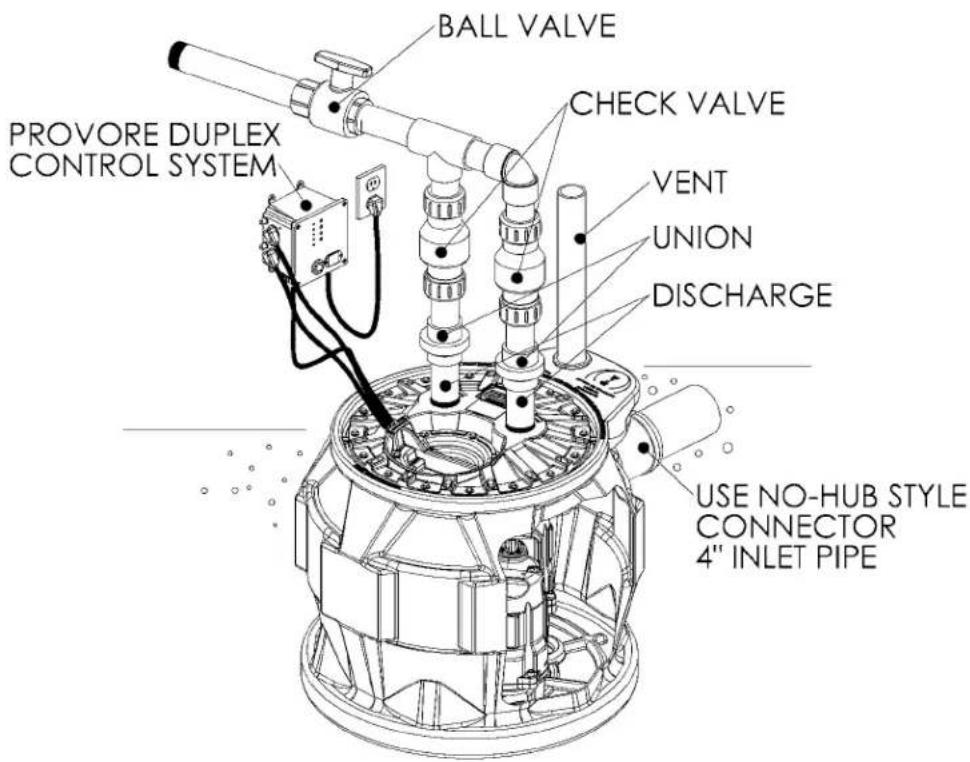
text_image
BALL VALVE PROVORE DUPLEX CONTROL SYSTEM CHECK VALVE VENT UNION DISCHARGE USE NO-HUB STYLE CONNECTOR 4" INLET PIPE4. QuickTree® and Access Cover
ProVore® P380 and P680 systems feature QuickTree® technology. The QuickTree® float system uses a stainless steel mounting rod (tree) and specially designed cord clamping brackets to affix the pump float and (optional) alarm float in the system. All floats are preset at the factory at optimum levels and do not require adjustment. NOTE: Field adjusting floats may cause improper activation or turn-off of the pump and optional alarm.
QuickTree ^® removal and float inspection: The QuickTree ^® system is located under the separate access cover to help ease inspection, service and replacement of a float. To inspect the float(s), simply unbolt the access cover and lift out the QuickTree ^® assembly from its holder. There is no need to disconnect plumbing or remove the pump. Pro-Series systems feature a manual grinder pump (with no switch attached directly to the pump). Operation of the pump is accomplished by the QuickTree ^® system.
Re-inserting the QuickTree ^® : After service or inspection of the floats, re-insert the QuickTree ^® into its holder. Cords from the pump, float switch and optional alarm need to be properly sealed as described below in the Integrated Cord Seal System.
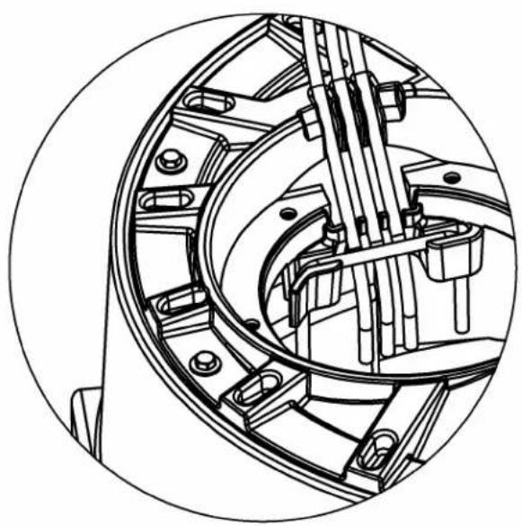
Integrated Cord Seal System: It is important that cords from the pump motor, float switch and optional alarm float are sealed in the specially designed rubber sealing channels under the access cover. Proper sealing is required to keep sewer gas from leaking from the system. Place the cords securely in the rubber channels as shown in FIGURE B. being careful to remove excessive cord "slack" from inside the system. IMPORTANT: Three cord channels are provided. For systems without the alarm option, only two channels will be used and the third must be "plugged" with an attached rubber plug seal. SEE FIGURE C. If the alarm cord is present, all three channels will be used. All rubber cover gaskets are permanently attached and do not require replacement.
IMPORTANT: Proper cord sealing – behind QuickTree ^® rod
natural_image
Technical line drawing of a mechanical assembly with internal components (no text or symbols)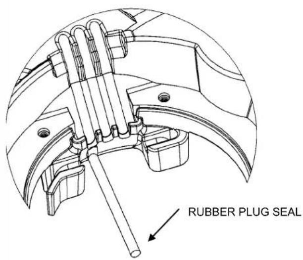
text_image
RUBBER PLUG SEALQuickTree® settings for ProVore® Systems:
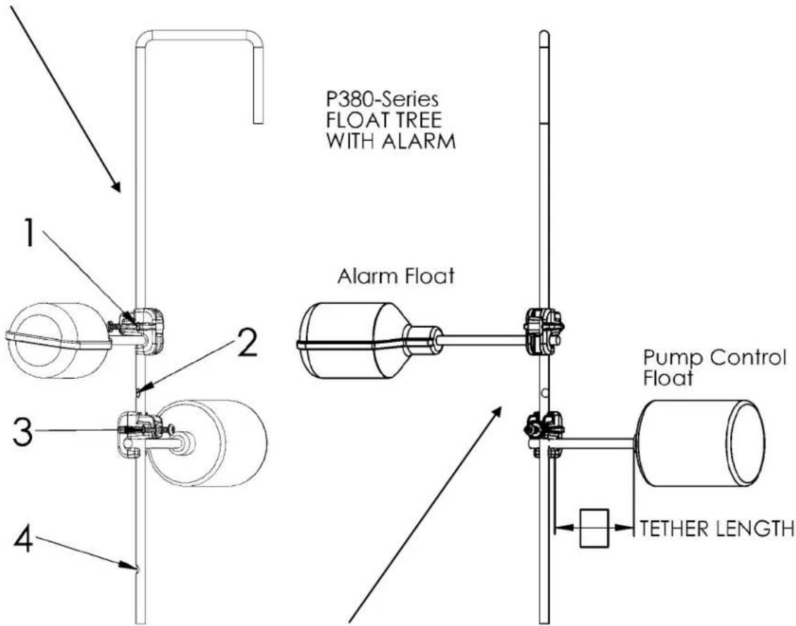
Float positions 1, 2, 3 and 4 are identified by a "flat" stamped into the stainless steel rod. 1 is highest, 4 is lowest.
| TETHER LENGTH(SWITCH TO CLAMP) | ||
| ROD POSITION | P380 & P680 | |
| Alarm Float C | Control Float | |
| 1 3.5" | ||
| 2 | ||
| 3 3.0" | ||
| 4 | ||
text_image
P380-Series FLOAT TREE WITH ALARM Alarm Float Pump Control Float TETHER LENGTHControl and alarm floats have different tether lengths. See above chart for proper tether length and correct rod position.
When servicing the QuickTree ^® place the switch cord into the trough or channel then slip the stainless steel rod through the clamp and tighten the screw with a Philips screw driver do not over tighten. Flats have been formed on the rod to designate float positioning the screw should be tightened onto the flat. The tether length is the amount of cord between the clamp and float.
5. Electrical Service and Operation

WARNING
- Risk of electric shock. Always disconnect the pump from the power source before handling or making adjustments.
- The electrical connections and wiring for a pump installation should only be made by qualified personnel.
- This pump is supplied with a grounding conductor or a grounding-type attachment plug. To reduce the risk of electric shock, be certain that the grounding conductor is connected only to a properly grounded control panel or, if equipped with a grounding-type plug, that it is connected to a properly grounded, grounding-type receptacle.
- Do not bypass grounding wires or remove ground prong from attachment plugs.
- Do not remove cord and strain relief, and do not connect conduit to pump.
- Do not use an extension cord.
- This pump requires separate, properly fused and grounded branch circuit. Make sure the power source is properly sized for the voltage and amperage requirements of the motor, as noted on the pump nameplate.
- The electrical outlet or panel shall be within the length limitations of the pump power cord, and at least 4 feet above floor level to minimize possible hazards from flood conditions.
- The installation must be in accordance with the National Electric Code and all applicable local codes and ordinances.
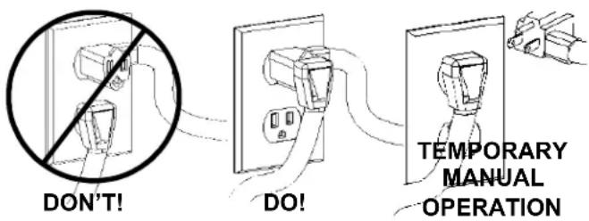
All P380 models come factory-equipped with the float switch mounted on the QuickTree ^ assembly. These models come with two cords - one to the float switch and the other to the pump motor. The switch cord has a series (piggyback) plug enabling the pump (motor) cord to be plugged into the back of it (See Fig.4). The purpose of this design is to allow manual operation of the pump. Note, on / off operation of the pump must be controlled by the circuit breaker.
For automatic operation the two cords should be interconnected and plugged into a separately fused, grounded outlet of proper amp capacity for your selected pump model. (See Section 1, General Information, or the pump nameplate for electrical specifications of your model.) Both cords are equipped with 3-prong plugs and must be plugged into a properly grounded 3-wire receptacle. DO NOT REMOVE THE GROUND PRONGS.
In the event of switch failure, the pump cord can be separated and plugged into the electrical outlet, directly bypassing the switch. For 115V and 230V single phase pumps should only be operated without the float switch by using the circuit breaker or panel disconnect. Do not let the pump run dry.
If the pump is to be wired directly into a control device or junction box, and it is necessary to remove the plugs, have a certified electrician do the wiring in accordance with the National Electric Code and applicable local codes.
Fig. 4 Piggyback plug installation.
text_image
DON'T! DO! TEMPORARY MANUAL OPERATION
WARNING
In 230V installations, one side on the line going to the pump is always "hot", whether the float switch is on or off. To avoid hazards, install a double pole disconnect near the pump installation.

flowchart
graph TD
    A["Power Supply"] --> B["Ground"]
    B --> C["Green White"]
    B --> D["Black White"]
    B --> E["Black White"]
    C --> F["Junction Box"]
    D --> F
    E --> F
    F --> G["Float Switch"]
    G --> H["Pump"]
Direct Wiring of 115V or 230V, Single Phase, Automatic Pumps P380 Systems
P680 duplex systems are connected to a controller that monitors the operation of the pumps. The controller will automatically alternate the two pumps each cycle to maintain equal wear. It will also monitor for high water conditions and alarms if necessary. The controller has visual indicators that show the operation of the sump as well as operator controls to test functionality. The controller will also identify a non-functioning component. For complete operation please reference the user manual for the controller.
Liberty offers both an indoor and outdoor version of the controller. Note, the cord ends must be removed in order to wire the outdoor version.

text_image
PDC-115 ProVore Duplex Control With Alarm 115V High Water Alarm Alarm Test Horn Disabled Horn Silences Pump Run Pump Run Test - Reset Power Liberty Pumps® WARNING! 9V Battery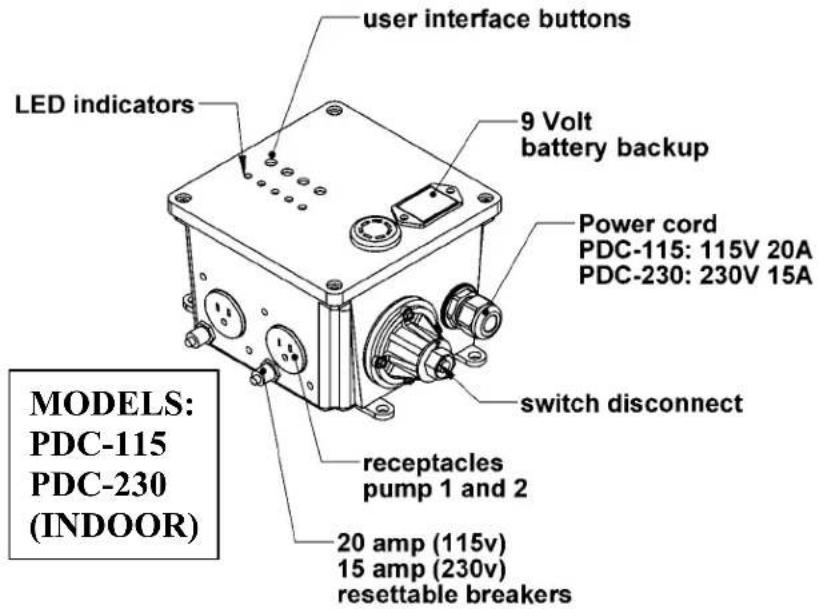
text_image
user interface buttons 9 Volt battery backup LED indicators Power cord PDC-115: 115V 20A PDC-230: 230V 15A switch disconnect receptacles pump 1 and 2 20 amp (115v) 15 amp (230v) resettable breakers MODELS: PDC-115 PDC-230 (INDOOR)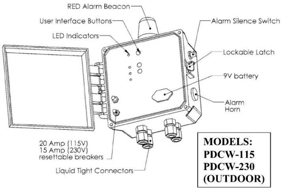
text_image
RED Alarm Beacon User Interface Buttons LED Indicators Alarm Silence Switch Lockable Latch 9V battery Alarm Horn 20 Amp (115V) 15 Amp (230V) resettable breakers Liquid Tight Connectors MODELS: PDCW-115 PDCW-230 (OUTDOOR)6. Maintenance and Troubleshooting

WARNING
Risk of electric shock. Always disconnect the pump from the power source before handling or making adjustments.
| Problem | Cause | Correction |
| Pump will not run. | Blown fuse or other interruption of power; improper voltage. | Check that the unit is securely plugged in.Have an electrician check all wiring for proper connections and adequate voltage and capacity. |
| Switch is unable to move to the "turn on" position due to interference with the side of basin or other obstruction | Position the pump or switch so that it has adequate clearance for free operation. | |
| Insufficient liquid level. | Make sure the liquid level is allowed to rise enough to activate switch(s). | |
| Defective switch. | Remove and replace switch. | |
| Pump will not turn off. | Switch(s) unable to move to the "turn off" position due to interference with the side of basin or other obstacle. | Position the pump or switch so that it has adequate clearance for free operation. |
| Defective switch. | Remove and replace switch. | |
| Pump runs or hums, but does not pump. | Discharge is blocked or restricted. | Check the discharge line for foreign material, including ice if the discharge line passes through or into cold areas. |
| Check valve is stuck closed or installed backwards. | Remove check valve(s) and examine for freedom of operation and proper installation. | |
| Gate or ball valve is closed. | Open gate or ball valve. | |
| Total lift is beyond pump's capability. | Try to route piping to a lower level. If not possible, a larger pump may be required.Consult the factory. | |
| Pump impeller is jammed or volute casing is plugged. | *Remove the pump from the basin, remove cutter and cutter plate clan the area around the impeller, reassemble and reinstall. The center screw uses a 6mm hex drive. The screw can be heated to remove thread locking compound. | |
| Pump runs periodically when fixtures are not in use. | Check valve was not installed, is stuck open or is leaking. | Remove check valve(s) and examine for freedom of operation and proper installation. |
| Fixtures are leaking. | Repair fixtures as required to eliminate leakage. | |
| Pump operates noisily. | Foreign objects in the impeller cavity. | * Remove the pump from the basin, remove cutter and cutter plate clan the area around the impeller, reassemble and reinstall. The center screw uses a 6mm hex drive. The screw can be heated to remove thread locking compound. |
| Broken impeller. | Consult the factory for information regarding replacement of impeller. | |
| Worn bearings. | Return pump to the factory or authorized repair station for repair. | |
| Piping attachments to building are too rigid. | Replace a portion of the discharge line with rubber hose or connector. |
*NOTE: Liberty Pumps, Inc. assumes no responsibility for damage or injury due to disassembly in the field. Disassembly, other than at Liberty Pumps or its authorized service centers, automatically voids warranty.
Supplemental Installation Instructions
PRO 380XL & 680XL Series 10' stack test basins
XL-Series sewage ejector basins are designed to withstand the 10' stack test required by some municipalities. Proper installation of the specified cover flange is essential to ensure that the test is met. Strict adherence to these instructions is required. Under no circumstances should the cover be installed in a manner inconsistent with these instructions.
Types of Systems:
XL Series Basins are available as Fully Assembled Systems complete with pump and discharge piping; as basin and cover assembly kits with no pump or plumbing and as basins only. Please follow the instructions below as required to correspond to the type of system you have.
Basin Installation:
- For all systems refer to the primary instructions as supplied with this ejector system or basin for excavating the pit, plumbing connections, and backfilling.
- If the top of the basin is below grade, an access riser model ARC18 is required. The maximum burial depth of 18" with respect to the top of the basin. Consult Liberty Pumps or your distributor for more information on ARC Series Access Risers. 1-800-543-2550.
Installing the pump in the XL Series Basin or XL Basin and Cover Assembly Kit:
- Liberty Pumps XL-Series basins purchased as separate components will require the appropriate 16-bolt Pro-Series cover assembly to make an effectively sealed ejector system. Contact the factory for the proper cover for your application.
- Size the length of the discharge piping to reach from the discharge of the pump to be within the discharge pipe socket with integral lip seal on the underside of the Pro-Series cover. Liberty Pumps Provore® utilizes a 17.50" long (toe nipple) for the PRO 380XL and 680XL Series Basins. Install the pipe into the threaded discharge of the pump.
- Lower the pump into the basin, fitting the pump legs into the Torque Stops.
- Insert power cord for the pump -- and the piggyback switch cord, if so equipped -- through the underside of the inspection cover hole and position cover over pipe nipple while aligning the bolt holes. Use sixteen 1/4 - 20 UNC bolts and washers to secure cover to the basin. Tighten bolts to 40 inch-pounds. WARNING: Do not over tighten bolts. The soft, integral gasket will conform to the top of the tank. The bolts may be re-torqued up to 60 inch-pounds to seal any leaks that may occur during a 10' stack test. Additionally, a small amount of RTV silicone sealant may be used should the gasket or inserts be damaged.
- Liberty Pumps recommends the use of manual type pumps and the appropriate Liberty QuickTree ^® switch kit for mounting of pump control and alarm floats. Contact the factory for ordering information. Install the QuickTree ^® Kit per the instructions included. Liberty Pumps automatic type pumps with piggyback float switches may also be used. Lay the power cable and switch cable in the grooves in the inspection cover recess as is shown in the primary instructions as included with this system. Attach the inspection cover to the main cover using six 1/4 - 20 UNC bolts and washers. Tighten the bolts furthest away from the power cord grooves first, torqueing to 40 inch-pounds. WARNING: Do not over tighten bolts. The soft, integral gasket will conform to the top of the cover and power cords. The bolts may be re-torqued up to 60 inch-pounds to seal any leaks that may occur during a 10' stack test. Additionally, a small amount of RTV silicone sealant may be used should the gasket or inserts be damaged.
3 Year Limited Warranty
*NOTE: Liberty Pumps, Inc. assumes no responsibility for damage or injury due to disassembly in the field. Disassembly, other than at Liberty Pumps or its authorized service centers, automatically voids warranty.
Liberty Pumps, Inc. warrants that pumps of its manufacture are free from all factory defects in material and workmanship for a period of 3 years from the date of purchase. The date of purchase shall be determined by a dated sales receipt noting the model and serial number of the pump. The dated sales receipt must accompany the returned pump if the date of return is more than 3 years from the "CODE" (date of manufacture) number noted on the pump nameplate.
The manufacturer's obligation under this Warranty shall be limited to the repair or replacement of any parts found by the manufacturer to be defective, provided the part or assembly is returned freight prepaid to the manufacturer or its authorized service center, and provided that none of the following warranty-voiding characteristics are evident.
The manufacturer shall not be liable under this Warranty if the product has not been properly installed; if it has been disassembled, modified, abused or tampered with; if the electrical cord has been cut, damaged or spliced; if the pump discharge has been reduced in size; if the pump has been used in water temperatures above the advertised rating, or water containing sand, lime, cement, gravel or other abrasives; if the product has been used to pump chemicals or hydrocarbons; if a non-submersible motor has been subjected to excessive moisture; or if the label bearing the serial, model and code number has been removed. Liberty Pumps, Inc. shall not be liable for any loss, damage or expenses resulting from installation or use of its products, or for consequential damages, including costs of removal, reinstallation or transportation.
There is no other express warranty. All implied warranties, including those of merchantability and fitness for a particular purpose, are limited to three years from the date of purchase.
This Warranty contains the exclusive remedy of the purchaser, and, where permitted, liability for consequential or incidental damages under any and all warranties are excluded.
LibertyPumps®
7000 Apple Tree Avenue
Bergen, NY 14416
Phone: (800) 543-2550
Fax: (585) 494-1839
www.libertypumps.com
natural_image
Cutaway view of a mechanical device showing internal components like a red cylinder and housing (no text or symbols visible)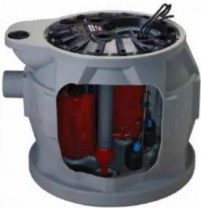
natural_image
Cutaway view of a mechanical device showing internal components and wiring (no text or symbols visible)IMPORTANT :
text_image
[659.02mm] Ø26" [748.04mm] Ø29 1/2" [730.25mm] 28 3/4" [596.90mm] Ø23 1/2" [596.90mm] 23 1/2" [361.06mm] 14 1/4" [431.80mm] 17" [234.95mm] 9 1/4" [609.60mm] 24" [81.28mm] 3 1/4" [609.60mm] 24" [723.90mm] Ø24 3/8"3. Installation et raccordements
ALARME (FACULTATIVE)
text_image
ÉVENT UNION CLAPET ANTIRETOUR CLAPET À BILLE ÉVACUATION UTILISER UN RACCORD SANS EMBOÎTEMENT TUYAU D'ALIMENTATION DE 4 PO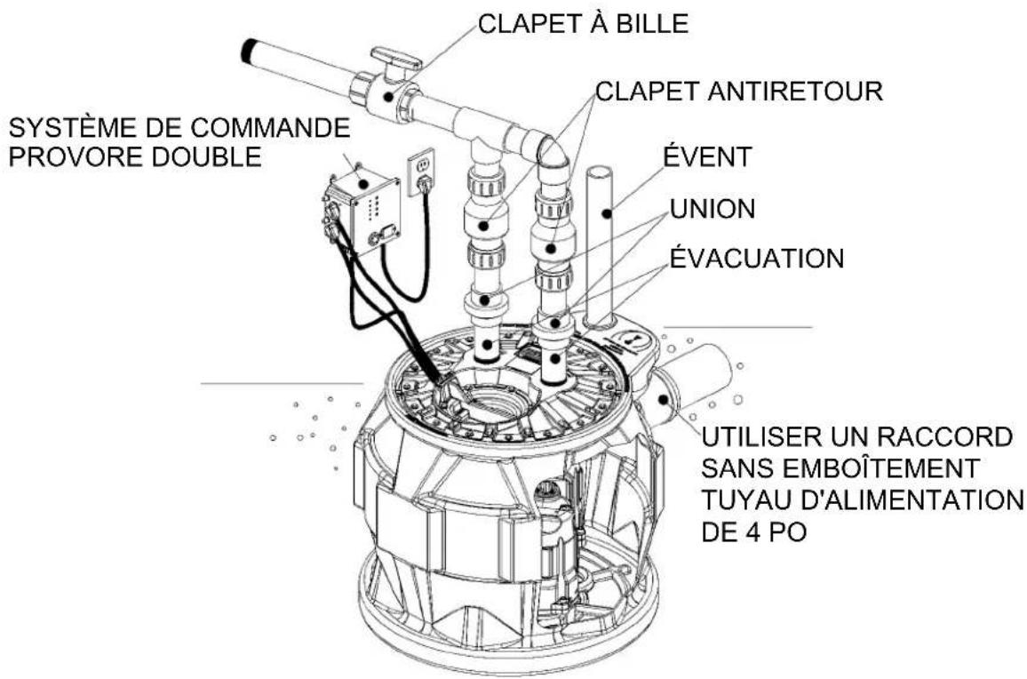
text_image
CLAPET À BILLE CLAPET ANTIRETOUR ÉVENT UNION ÉVACUATION SYSTÈME DE COMMANDE PROVORE DOUBLE UTILISER UN RACCORD SANS EMBOÎTEMENT TUYAU D'ALIMENTATION DE 4 POtext_image
DPOUNT! CDO! TEMPORARY MANUAL OPERATIONAVERTISSEMENT
text_image
PDC-115 ProVore Duplex Control With Alarm 115V High Water Alarm Alarm Test Horn Disabled Horn Silence Pump Run Pump Run Test - Reset Power Note: If High Water Alarm light is fishing, an alarm float error has occurred. Note: If Horn Disabled light is fishing, horn will not sound. To place horn in active state press Horn Silence button until Horn Disabled light is out. Horn Silence will auto reset in 12 hours. Press Pump Plan button to verify sump operation. Note: If one of the pump fails to run 3 times in a row, the Pump Run light associated with the pump will FLASH. If both Pump Run lights are floating, a pump float error has occurred. Press and hold Reset button for a minimum of 4 seconds to reset reset. 9V Battery Liberty Pumps® IN WARNING! ELECTRICAL BREAK NUMBER: Powered by the Power Supply Control System, the power of the power supply system.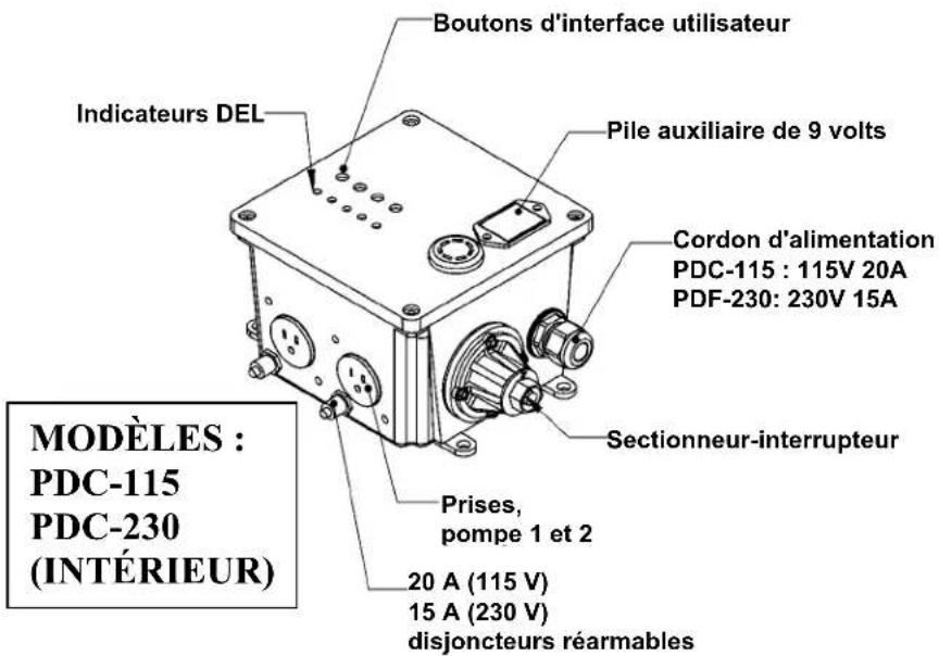
Panel de control interior
• P382PRG101 - 1 hp., 115 Voltios
• P382PRG102 - 1 hp., 230 Voltios
Panel de control exterior
• P382PRG101W - 1 hp., 115 Voltios
• P382PRG102W - 1 hp., 230 Voltios
Índice
natural_image
Cutaway view of a mechanical pump or motor assembly showing internal components (no text or symbols visible)