GD002G - Grinder MAKITA - Free user manual and instructions
Find the device manual for free GD002G MAKITA in PDF.

User questions about GD002G MAKITA
0 question about this device. Answer the ones you know or ask your own.
Ask a new question about this device
Download the instructions for your Grinder in PDF format for free! Find your manual GD002G - MAKITA and take your electronic device back in hand. On this page are published all the documents necessary for the use of your device. GD002G by MAKITA.
USER MANUAL GD002G MAKITA
natural_image
Technical line drawing of a mechanical assembly (no text or symbols)
text_image
Fig.1 1 2 3 1 2000 2100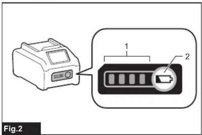
text_image
Fig.2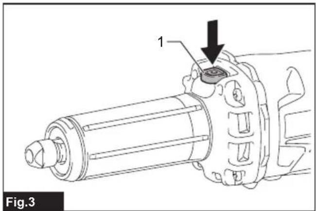
text_image
1 Fig.3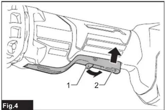
text_image
Fig.4 1 2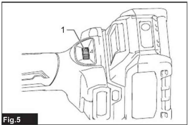
text_image
1 Fig.5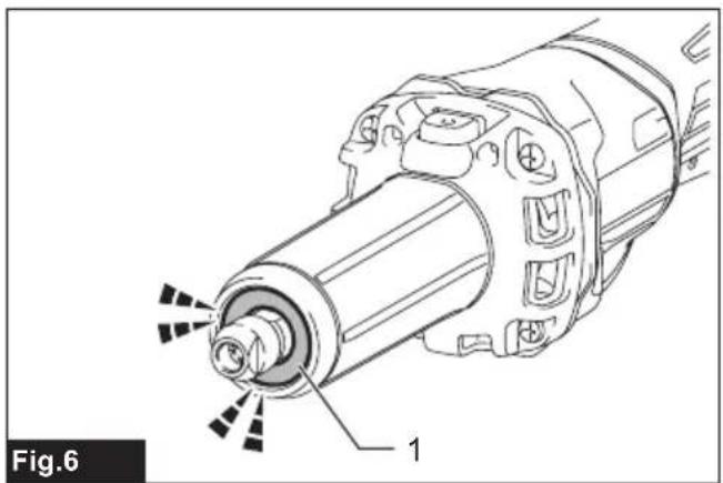
natural_image
Technical line drawing of a mechanical component with labeled parts (no text or symbols beyond label)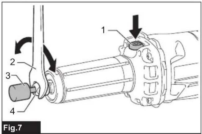
text_image
1 2 3 4 Fig.7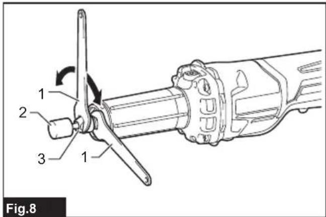
text_image
1 2 3 1 Fig.8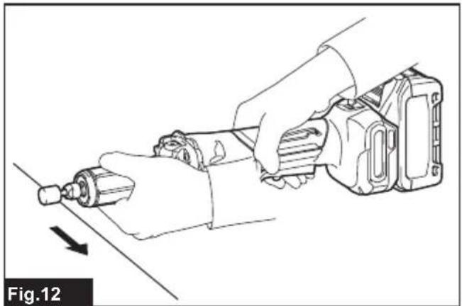
natural_image
Line drawing of a hand using a tool to adjust or install a mechanical component, with no visible text or symbols.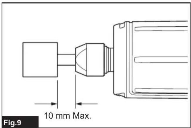
text_image
Fig.9 10 mm Max.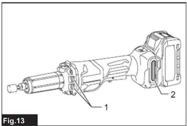
text_image
Fig.13 1 2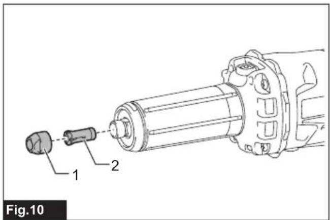
text_image
Fig.10 1 2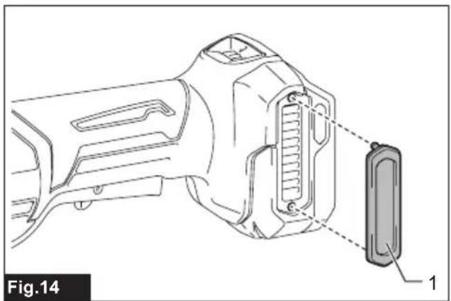
natural_image
Technical line drawing of a handheld device with labeled component (no text or symbols present)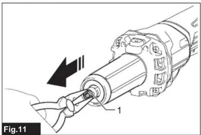
natural_image
Technical diagram of a mechanical assembly with labeled component '1' and directional arrow (no text or symbols beyond label)SPECIFICATIONS
| Model: GD002G | ||
| Collet size (country specific) 6 mm or 6.35 mm (1/4") | ||
| Max. accessory size Max. wheel | point diameter | 32 mm |
| Max. sanding wheel diameter 52 mm | ||
| Max. wire brush diameter 52 mm | ||
| Max. polishing wheel diameter 52 mm | ||
| Max. carving accessory diameter | 52 mm | |
| Max. cut-off wheel diameter 52 mm | ||
| Max. mandrel (shank) length 46 mm | ||
| Rated speed (n)/No load speed ( n_0 ) 7,000 - 29,000 min | -1 | |
| Overall length with BL4040 458 mm | ||
| Net weight 2.2 - 3.4 kg | ||
| Rated voltage D.C. 36 V - 40 V max | ||
• Due to our continuing program of research and development, the specifications herein are subject to change without notice.
• Specifications may differ from country to country.
- The net weight value includes the lightest and heaviest combination of the attachment(s) and battery cartridge(s) which are specified in the instruction manual.
Applicable battery cartridge and charger
| Battery cartridge | BL4020* / BL4025* / BL4040* / BL4040F* /BL4050F* / BL4080F*: Recommended battery |
| Charger | DC40RA / DC40RB / DC40RC / DC40WA / BCC01 / BCC02 |
• Some of the battery cartridges and chargers listed above may not be available depending on your region of residence.
WARNING: Only use the battery cartridges and chargers listed above. Use of any other battery cartridges and chargers may cause injury and/or fire.
Applicable cord connected power source
| Portable power pack | PDC01 / PDC1200 / PDC1500 |
• The cord connected power source(s) listed above may not be available depending on your region of residence.
• Before using the cord connected power source, read instruction and cautionary markings on them.
Intended use
The tool is intended for grinding ferrous materials or deburring castings, as well as for sanding, wire brushing, polishing, carving, and cutting-off.
Noise
The typical A-weighted noise level determined according to EN60745-2-23:
| Work mode | Sound pressure level (LPA): | Sound power level (LWA): | Uncertainty (K): |
| No load (artificial wheel 25-50 mm) | 78 dB(A) | - | 3 dB(A) |
| No load (artificial wheel 50 mm over) | 80 dB(A) | 91 dB(A) | 3 dB(A) |
The noise level under working may exceed 80 dB (A).
NOTE: The declared noise emission value(s) has been measured in accordance with a standard test method and may be used for comparing one tool with another.
NOTE: The declared noise emission value(s) can also be used in a preliminary assessment of exposure.
⚠ WARNING: Wear ear protection.
⚠ WARNING: The noise emission during actual use of the power tool can differ from the declared total value(s) depending on the ways in which the tool is used.
⚠ WARNING: Be sure to identify safety measures to protect the operator that are based on an estimation of exposure in the actual conditions of use (taking account of all parts of the operating cycle such as the times when the tool is switched off and when it is running idle in addition to the trigger time).
Vibration
The continuous vibration total value (tri-axial vector sum) determined according to EN60745-2-23:
| Work mode Vibration | emis-sion (ah): | Uncertainty (K) : |
| Surface grinding (artificial wheel 25-50 mm) | 5.7 m/s2 | 1.5 m/s2 |
| Surface grinding (artifi-cial wheel 50 mm over) | 14.6 m/s2 | 1.5 m/s2 |
NOTE: The declared vibration total value(s) has been measured in accordance with a standard test method and may be used for comparing one tool with another.
NOTE: The declared vibration total value(s) can also be used in a preliminary assessment of exposure.
⚠ WARNING: The vibration emission during actual use of the power tool can differ from the declared total value(s) depending on the ways in which the tool is used.
WARNING: Be sure to identify safety measures to protect the operator that are based on an estimation of exposure in the actual conditions of use (taking account of all parts of the operating cycle such as the times when the tool is switched off and when it is running idle in addition to the trigger time).
Declarations of Conformity
For European countries only
The Declarations of conformity are included in Annex A to this instruction manual.
SAFETY WARNINGS
General power tool safety warnings
⚠ WARNING Read all safety warnings, instructions, illustrations and specifications provided with this power tool. Failure to follow all instructions listed below may result in electric shock, fire and/or serious injury.
Save all warnings and instructions for future reference.
The term "power tool" in the warnings refers to your mains-operated (corded) power tool or battery-operated (cordless) power tool.
Cordless die grinder safety warnings
Safety warnings common for grinding, sanding, wire brushing, polishing, carving or abrasive cutting-off operations:
- This power tool is intended to function as a grinder, sander, wire brush, polisher, carving or cut-off tool. Read all safety warnings, instructions, illustrations and specifications provided with this power tool. Failure to follow all instructions listed below may result in electric shock, fire and/or serious injury.
- Do not use accessories which are not specifically designed and recommended by the tool manufacturer. Just because the accessory can be attached to your power tool, it does not assure safe operation.
- The rated speed of the grinding accessories must be at least equal to the maximum speed marked on the power tool. Grinding accessories running faster than their rated speed can break and fly apart.
- The outside diameter and the thickness of your accessory must be within the capacity rating of your power tool. Incorrectly sized accessories cannot be adequately controlled.
- The arbour size of wheels, sanding drums or any other accessory must properly fit the spindle or collet of the power tool. Accessories that do not match the mounting hardware of the power tool will run out of balance, vibrate excessively and may cause loss of control.
- Mandrel mounted wheels, sanding drums, cutters or other accessories must be fully inserted into the collet or chuck. If the mandrel is insufficiently held and/or the overhang of the wheel is too long, the mounted wheel may become loose and be ejected at high velocity.
- Do not use a damaged accessory. Before each use inspect the accessory such as abrasive wheels for chips and cracks, sanding drum for cracks, tear or excess wear, wire brush for loose or cracked wires. If power tool or accessory is dropped, inspect for damage or install an undamaged accessory. After inspecting and installing an accessory, position yourself and
bystanders away from the plane of the rotating accessory and run the power tool at maximum no-load speed for one minute. Damaged accessories will normally break apart during this test time.
- Wear personal protective equipment.
Depending on application, use face shield, safety goggles or safety glasses. As appropriate, wear dust mask, hearing protectors, gloves and workshop apron capable of stopping small abrasive or workpiece fragments.
The eye protection must be capable of stopping flying debris generated by various operations.
The dust mask or respirator must be capable of filtrating particles generated by your operation.
Prolonged exposure to high intensity noise may cause hearing loss.
- Keep bystanders a safe distance away from work area. Anyone entering the work area must wear personal protective equipment.
Fragments of workpiece or of a broken accessory may fly away and cause injury beyond immediate area of operation.
-
Hold the power tool by insulated gripping surfaces only, when performing an operation where the cutting accessory may contact hidden wiring. Cutting accessory contacting a "live" wire may make exposed metal parts of the power tool "live" and could give the operator an electric shock.
-
Always hold the tool firmly in your hand(s) during the start-up. The reaction torque of the motor, as it accelerates to full speed, can cause the tool to twist.
-
Use clamps to support workpiece whenever practical. Never hold a small workpiece in one hand and the tool in the other hand while in use. Clamping a small workpiece allows you to use your hand(s) to control the tool. Round material such as dowel rods, pipes or tubing have a tendency to roll while being cut and may cause the bit to bind or jump toward you.
-
Never lay the power tool down until the accessory has come to a complete stop. The spinning accessory may grab the surface and pull the power tool out of your control.
-
After changing the bits or making any adjustments, make sure the collet nut, chuck or any other adjustment devices are securely tightened. Loose adjustment devices can unexpectedly shift, causing loss of control, loose rotating components will be violently thrown.
-
Do not run the power tool while carrying it at your side. Accidental contact with the spinning accessory could snag your clothing, pulling the accessory into your body.
-
Regularly clean the power tool's air vents. The motor's fan will draw the dust inside the housing and excessive accumulation of powdered metal may cause electrical hazards.
-
Do not operate the power tool near flammable materials. Sparks could ignite these materials.
-
Do not use accessories that require liquid coolants. Using water or other liquid coolants may result in electrocution or shock.
Kickback and related warnings
Kickback is a sudden reaction to a pinched or snagged rotating wheel, sanding band, brush or any other accessory. Pinching or snagging causes rapid stalling of the rotating accessory which in turn causes the uncontrolled power tool to be forced in the direction opposite of the accessory's rotation.
For example, if an abrasive wheel is snagged or pinched by the workpiece, the edge of the wheel that is entering into the pinch point can dig into the surface of the material causing the wheel to climb out or kick out. The wheel may either jump toward or away from the operator, depending on direction of the wheel's movement at the point of pinching. Abrasive wheels may also break under these conditions.
Kickback is the result of power tool misuse and/or incorrect operating procedures or conditions and can be avoided by taking proper precautions as given below.
-
Maintain a firm grip on the power tool and position your body and arm to allow you to resist kickback forces. The operator can control kickback forces, if proper precautions are taken.
-
Use special care when working corners, sharp edges etc. Avoid bouncing and snagging the accessory. Corners, sharp edges or bouncing have a tendency to snag the rotating accessory and cause loss of control or kickback.
-
Do not attach a toothed saw blade. Such blades create frequent kickback and loss of control.
-
Always feed the bit into the material in the same direction as the cutting edge is exiting from the material (which is the same direction as the chips are thrown). Feeding the tool in the wrong direction causes the cutting edge of the bit to climb out of the work and pull the tool in the direction of this feed.
-
When using rotary files, cut-off wheels, high-speed cutters or tungsten carbide cutters, always have the work securely clamped. These wheels will grab if they become slightly canted in the groove, and can kickback. When a cut-off wheel grabs, the wheel itself usually breaks. When a rotary file, high-speed cutter or tungsten carbide cutter grabs, it may jump from the groove and you could lose control of the tool.
Safety warnings specific for grinding and abrasive cutting-off operations:
-
Use only wheel types that are recommended for your power tool and only for recommended applications. For example: do not grind with the side of a cut-off wheel. Abrasive cut-off wheels are intended for peripheral grinding, side forces applied to these wheels may cause them to shatter.
-
Do not "jam" a cut-off wheel or apply excessive pressure. Do not attempt to make an excessive depth of cut. Overstressing the wheel increases the loading and susceptibility to twisting or snagging of the wheel in the cut and the possibility of kickback or wheel breakage.
-
Do not position your hand in line with and behind the rotating wheel. When the wheel, at the point of operation, is moving away from your hand, the possible kickback may propel the spinning wheel and the power tool directly at you.
-
When wheel is pinched, snagged or when interrupting a cut for any reason, switch off the power tool and hold the power tool motionless until the wheel comes to a complete stop. Never attempt to remove the cut-off wheel from the cut while the wheel is in motion otherwise kickback may occur. Investigate and take corrective action to eliminate the cause of wheel pinching or snagging.
- Do not restart the cutting operation in the workpiece. Let the wheel reach full speed and carefully re-enter the cut. The wheel may bind, walk up or kickback if the power tool is restarted in the workpiece.
- Support panels or any oversized workpiece to minimize the risk of wheel pinching and kick-back. Large workpieces tend to sag under their own weight. Supports must be placed under the workpiece near the line of cut and near the edge of the workpiece on both sides of the wheel.
- Use extra caution when making a "pocket cut" into existing walls or other blind areas. The protruding wheel may cut gas or water pipes, electrical wiring or objects that can cause kickback.
Safety warnings specific for wire brushing operations:
- Be aware that wire bristles are thrown by the brush even during ordinary operation. Do not overstress the wires by applying excessive load to the brush. The wire bristles can easily penetrate light clothing and/or skin.
- Allow brushes to run at operating speed for at least one minute before using them. During this time no one is to stand in front or in line with the brush. Loose bristles or wires will be discharged during the run-in time.
- Direct the discharge of the spinning wire brush away from you. Small particles and tiny wire fragments may be discharged at high velocity during the use of these brushes and may become imbedded in your skin.
Additional Safety Warnings:
- The tool is intended for use with bonded abrasive wheel points (grinding stones) permanently mounted on plain, unthreaded mandrel (shanks).
- Make sure the wheel is not contacting the workpiece before the switch is turned on.
- Before using the tool on an actual workpiece, let it run for a while. Watch for vibration or wobbling that could indicate poor installation or a poorly balanced wheel.
- Use the specified surface of the wheel to perform the grinding.
- Watch out for flying sparks. Hold the tool so that sparks fly away from you and other persons or flammable materials.
- Do not leave the tool running. Operate the tool only when hand-held.
- Do not touch the workpiece immediately after operation; it may be extremely hot and could burn your skin.
- Observe the instructions of the manufacturer for correct mounting and use of wheels.
Handle and store wheels with care.
- Check that the workpiece is properly supported.
- Do not use the tool on any materials containing asbestos.
- Always be sure you have a firm footing. Be sure no one is below when using the tool in high locations.
SAVE THESE INSTRUCTIONS.
WARNING: DO NOT let comfort or familiarity with product (gained from repeated use) replace strict adherence to safety rules for the subject product. MISUSE or failure to follow the safety rules stated in this instruction manual may cause serious personal injury.
Important safety instructions for battery cartridge
- Before using battery cartridge, read all instructions and cautionary markings on (1) battery charger, (2) battery, and (3) product using battery.
- Do not disassemble or tamper with the battery cartridge. It may result in a fire, excessive heat, or explosion.
- If operating time has become excessively shorter, stop operating immediately. It may result in a risk of overheating, possible burns and even an explosion.
- If electrolyte gets into your eyes, rinse them out with clear water and seek medical attention right away. It may result in loss of your eyesight.
- Do not short the battery cartridge:
(1) Do not touch the terminals with any conductive material.
(2) Avoid storing battery cartridge in a container with other metal objects such as nails, coins, etc.
(3) Do not expose battery cartridge to water or rain.
A battery short can cause a large current flow, overheating, possible burns and even a breakdown.
- Do not store and use the tool and battery cartridge in locations where the temperature may reach or exceed 50 °C (122 °F).
- Do not incinerate the battery cartridge even if it is severely damaged or is completely worn out. The battery cartridge can explode in a fire.
- Do not nail, cut, crush, throw, drop the battery cartridge, or hit against a hard object to the battery cartridge. Such conduct may result in a fire, excessive heat, or explosion.
- Do not use a damaged battery.
- The contained lithium-ion batteries are subject to the Dangerous Goods Legislation requirements.
For commercial transports e.g. by third parties, forwarding agents, special requirement on packaging and labeling must be observed.
For preparation of the item being shipped,
consulting an expert for hazardous material is required. Please also observe possibly more detailed national regulations.
Tape or mask off open contacts and pack up the battery in such a manner that it cannot move around in the packaging.
- When disposing the battery cartridge, remove it from the tool and dispose of it in a safe place. Follow your local regulations relating to disposal of battery.
- Use the batteries only with the products specified by Makita. Installing the batteries to non-compliant products may result in a fire, excessive heat, explosion, or leak of electrolyte.
- If the tool is not used for a long period of time, the battery must be removed from the tool.
- During and after use, the battery cartridge may take on heat which can cause burns or low temperature burns. Pay attention to the handling of hot battery cartridges.
- Do not touch the terminal of the tool immediately after use as it may get hot enough to cause burns.
- Do not allow chips, dust, or soil stuck into the terminals, holes, and grooves of the battery cartridge. It may cause heating, catching fire, burst and malfunction of the tool or battery cartridge, resulting in burns or personal injury.
- Unless the tool supports the use near high-voltage electrical power lines, do not use the battery cartridge near high-voltage electrical power lines. It may result in a malfunction or breakdown of the tool or battery cartridge.
- Keep the battery away from children.
SAVE THESE INSTRUCTIONS.
⚠️CAUTION: Only use genuine Makita batteries. Use of non-genuine Makita batteries, or batteries that have been altered, may result in the battery bursting causing fires, personal injury and damage. It will also void the Makita warranty for the Makita tool and charger.
NOTICE: Makita is not responsible for any accidents resulting from the use of non-genuine Makita batteries or batteries that have been modified. Genuine Makita batteries have been rigorously evaluated for compatibility with Makita tools and chargers, in line with applicable legislation and safety standards.
Tips for maintaining maximum battery life
- Charge the battery cartridge before completely discharged. Always stop tool operation and charge the battery cartridge when you notice less tool power.
- Never recharge a fully charged battery cartridge. Overcharging shortens the battery service life.
-
Charge the battery cartridge with room temperature at 10 °C - 40 °C (50 °F - 104 °F). Let a hot battery cartridge cool down before charging it.
-
When not using the battery cartridge, remove it from the tool or the charger.
- Charge the battery cartridge if you do not use it for a long period (more than six months).
FUNCTIONAL DESCRIPTION
WARNING: Always be sure that the tool is switched off and the battery cartridge is removed before adjusting or checking function on the tool.
Installing or removing battery cartridge
⚠️ CAUTION: Always switch off the tool before installing or removing of the battery cartridge.
CAUTION: Hold the tool and the battery cartridge firmly when installing or removing battery cartridge. Failure to hold the tool and the battery cartridge firmly may cause them to slip off your hands and result in damage to the tool and battery cartridge and a personal injury.
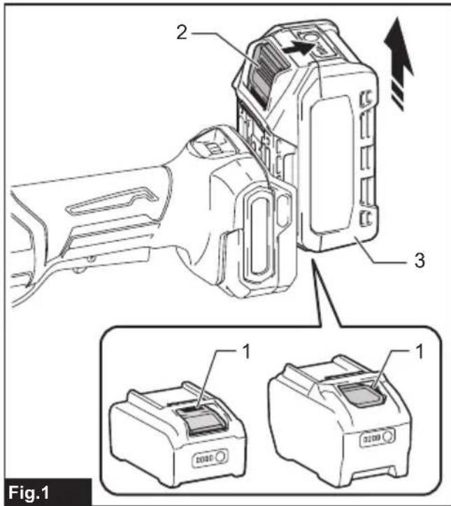
To install the battery cartridge, align the tongue on the battery cartridge with the groove in the housing and slip it into place. Insert it all the way until it locks in place with a little click. If you can see the red indicator as shown in the figure, it is not locked completely.
To remove the battery cartridge, slide it from the tool while sliding the button on the front of the cartridge.
▶ Fig.1: 1. Red indicator 2. Button 3. Battery cartridge
CAUTION: Always install the battery cartridge fully until the red indicator cannot be seen. If not, it may accidentally fall out of the tool, causing injury to you or someone around you.
⚠️ CAUTION: Do not install the battery cartridge forcibly. If the cartridge does not slide in easily, it is not being inserted correctly.
Indicating the remaining battery capacity
Press the check button on the battery cartridge to indicate the remaining battery capacity. The indicator lamps light up for a few seconds.
▶ Fig.2: 1. Indicator lamps 2. Check button
| Indicator lamps Remaining | capacity | ||
| Lighted Off | Blinking | ||
| 75% to 100% | |||
| 50% to 75% | |||
| 25% to 50% | |||
| 0% to 25% | |||
| Charge the battery. | |||
| The battery may have malfunctioned. | |||
NOTE: Depending on the conditions of use and the ambient temperature, the indication may differ slightly from the actual capacity.
NOTE: The first (far left) indicator lamp will blink when the battery protection system works.
Tool / battery protection system
The tool is equipped with a tool/battery protection system. This system automatically cuts off power to the motor to extend tool and battery life. The tool will automatically stop during operation if the tool or battery is placed under one of the following conditions:
Overload protection
When the tool/battery is operated in a manner that causes it to draw an abnormally high current, the tool automatically stops without any indication. In this situation, turn the tool off and stop the application that caused the tool to become overloaded. Then turn the tool on to restart.
Overheat protection
When the tool/battery is overheated, the tool stops automatically and the lamp blinks. Let the tool cool down before turning the tool on again.
Overdischarge protection
When the battery capacity is not enough, the tool stops automatically. In this case, remove the battery from the tool and charge the battery.
Releasing protection lock
When the protection system works repeatedly, the tool is locked.
In this situation, the tool does not start even if turning the tool off and on. To release the protection lock, remove the battery, set it to the battery charger and wait until the charging finishes.
Protections against other causes
Protection system is also designed for other causes that could damage the tool and allows the tool to stop automatically. Take all the following steps to clear the causes, when the tool has been brought to a temporary halt or stop in operation.
- Make sure that all switch(es) is/are in the off position, and then turn the tool on again to restart.
- Charge the battery(ies) or replace it/them with recharged battery(ies).
- Let the tool and battery(ies) cool down.
If no improvement can be found by restoring protection system, then contact your local Makita Service Center.
Shaft lock

WARNING: Never actuate the shaft lock when the spindle is moving. It may cause serious injury or tool damage.

WARNING: Make sure that the shaft lock fully turns to its original position after releasing it.
Press the shaft lock to prevent spindle rotation when installing or removing accessories.
▶ Fig.3: 1. Shaft lock
Switch action

CAUTION: Before installing the battery cardge into the tool, always check to see that the switch lever actuates properly and returns to the FF" position when released.

CAUTION: For your safety, this tool is equipped with lock-off lever which prevents the tool from unintended starting. NEVER use the tool to run when you simply pull the switch lever without pulling the lock-off lever. Return the tool our authorized service center for proper repairs BEFORE further usage.

CAUTION: Do not pull the switch lever hard without pulling the lock-off lever. This can cause switch breakage.

CAUTION: NEVER tape down or defeat purse and function of lock-off lever.
To prevent the switch lever from being accidentally pulled, a lock-off lever is provided.
To start the tool, pull the lock-off lever toward the operator and then pull the switch lever.
To stop the tool, release the switch lever.
▶ Fig.4: 1. Lock-off lever 2. Switch lever
Speed adjusting dial
The rotation speed of the tool can be changed by turning the speed adjusting dial. The table below shows the number on the dial and the corresponding rotation speed.
▶ Fig.5: 1. Speed adjusting dial
| Number Speed | |
| 1 7,000 min | -1 |
| 2 12,500 min | -1 |
| 3 18,000 min | -1 |
| 4 23,500 min | -1 |
| 5 29,000 min | -1 |
NOTICE: If the tool is operated continuously at low speed for a long time, the motor will get overloaded, resulting in tool malfunction.
NOTICE: The speed adjusting dial can be turned only as far as 5 and back to 1. Do not force it past 5 or 1, or the speed adjusting function may no longer work.
Lighting up the front lamp
⚠️CAUTION: Do not look in the light or see the source of light directly.
The front lamp lights up for 10 seconds after installing the battery cartridge or lights up continuously while the switch is ON.
The lamp goes out 10 seconds after the switch is OFF.
▶ Fig.6: 1. Front lamp
Disabling or enabling the lamp status
To disable or enable the lamp status, follow the steps below.
- Insert the battery cartridge into the tool.
- Set the speed adjusting dial to "5".
- Turn the speed adjusting dial to "1", and then set it back to "5".
NOTE: The lamp status can be changed within 10 seconds of inserting the battery cartridge. Once the switch is turned on, the lamp status cannot be changed, even if it is within 10 seconds of inserting the battery cartridge.
NOTE: The lamp status can also be changed by setting the speed adjusting dial to "1" - "5" - "1".
NOTE: To set the lamp status again, first remove the battery cartridge and then adjust the speed adjusting dial.
NOTE: The lamp status will be the same as it was the last time the tool was used.
Accidental re-start preventive function
When installing the battery cartridge while the switch is ON, the tool does not start.
To start the tool, turn off the switch, and turn it on again.
Active Feedback sensing Technology
The tool electronically detects situations where the wheel or accessory may be at risk to be bound. In the situation, the tool is automatically shut off to prevent further rotation of the spindle (it does not prevent kickback).
To restart the tool, switch off the tool first, remove the cause of sudden drop in the rotation speed, and then turn the tool on.
Soft start feature
Constant speed control
Possible to get fine finish, because the rotating speed is kept constant even under the loaded condition.
Electric brake
Electric brake is activated after the tool is switched off. The brake does not work when the power supply is shut down, such as the battery is removed accidentally, with the switch still on.
ASSEMBLY
CAUTION: Always be sure that the tool is switched off and the battery cartridge is removed before carrying out any work on the tool.
Installing or removing accessory
⚠️ CAUTION: Use the correct size collet cone for the accessory which you intend to use.
NOTICE: Do not tighten the collet nut without inserting an accessory. Otherwise it can lead to breakage of the collet cone.
Using shaft lock
Press the shaft lock firmly so that the spindle cannot revolve. Loosen the collet nut counterclockwise and insert the accessory into the collet nut. Tighten the collet nut clockwise by using the wrench.
▶ Fig.7: 1. Shaft lock 2. Wrench 3. Accessory 4. Collet nut
Using two wrenches
Loosen the collet nut counterclockwise and insert the accessory into the collet nut. Use one wrench to hold the spindle. Using another wrench, turn the collet nut clockwise to tighten securely.
▶ Fig.8: 1. Wrench 2. Accessory 3. Collet nut
NOTE: If you cannot insert the accessory into the collet nut after loosening the collet nut, the collet cone may obstruct the accessory. In that case, remove the collet nut and reposition the collet cone.
The accessory should not be mounted more than 10 mm from the collet nut. Exceeding this distance could cause vibration or a broken shaft.
▶ Fig.9
Changing collet cone
- Loosen the collet nut and remove it.
- Replace the installed collet cone with desired collet cone.
- Reinstall the collet nut.
▶ Fig.10: 1. Collet nut 2. Collet cone
If the collet cone cannot be removed, pinch the collet cone with long-nose pliers and remove it.
To prevent the collet cone deformation, do not apply excessive force when pinching it.
⚠️CAUTION: Apply light pressure on the tool.
Excessive pressure on the tool will only cause a poor finish and overloading of the motor.
⚠️CAUTION: The accessory continues to rotate after the tool is switched off.
⚠️CAUTION: Hold the tool securely with both hands.
⚠️CAUTION: When using the accessories that are sold on the market, always make sure the rated speed of the accessories must be at least equal to the maximum speed marked on the tool.
Turn the tool on without the accessory making any contact with the workpiece and wait until the accessory attains full speed. Then apply the accessory to the workpiece gently.
▶ Fig.12
NOTE: When operating side grinding, moving the tool in the leftward direction slowly can obtain a good finish.
MAINTENANCE
⚠️CAUTION: Always be sure that the tool is switched off and the battery cartridge is removed before attempting to perform inspection or maintenance.
NOTICE: Never use gasoline, benzine, thinner, alcohol or the like. Discoloration, deformation or cracks may result.
To maintain product SAFETY and RELIABILITY, repairs, any other maintenance or adjustment should be performed by Makita Authorized or Factory Service Centers, always using Makita replacement parts.
Dressing wheel point
When the wheel point becomes "loaded" with various bits and particles, you should dress the wheel point with the dressing stone.
Air vent cleaning
The tool and its air vents have to be kept clean.
Regularly clean the tool's air vents or whenever the vents start to become obstructed.
▶ Fig.13: 1. Exhaust vent 2. Inhalation vent
Remove the dust cover from inhalation vent and clean it for smooth air circulation.
▶ Fig.14: 1. Dust cover
NOTICE: Clean out the dust cover when it is clogged with dust or foreign matters. Continuing operation with a clogged dust cover may damage the tool.
OPTIONAL ACCESSORIES
CAUTION: These accessories or attachments are recommended for use with your Makita tool specified in this manual. The use of any other accessories or attachments might present a risk of injury to persons. Only use accessory or attachment for its stated purpose.
If you need any assistance for more details regarding these accessories, ask your local Makita Service Center.
- Wheel points
- Collet cone (3 mm, 6 mm, 8 mm, 1/4", 1/8")
- Collet nut
- Wrench 13
- Makita genuine battery and charger
NOTE: Some items in the list may be included in the tool package as standard accessories. They may differ from country to country.
SPÉCIFICATIONS
▶ Fig.14: 1. Pare-poussière
⚠ WAARSCHUWING: Draag gehoorbescherming.
VEILIGHEIDSWAAR- SCHUWINGEN
▶ Fig.14: 1. Stofrooster