INFRARED-125 - Pan Soler & Palau - Free user manual and instructions
Find the device manual for free INFRARED-125 Soler & Palau in PDF.


User questions about INFRARED-125 Soler & Palau
0 question about this device. Answer the ones you know or ask your own.
Ask a new question about this device
Download the instructions for your Pan in PDF format for free! Find your manual INFRARED-125 - Soler & Palau and take your electronic device back in hand. On this page are published all the documents necessary for the use of your device. INFRARED-125 by Soler & Palau.
USER MANUAL INFRARED-125 Soler & Palau
natural_image
Exterior view of a modern electric heater with heat dissipation panel (no text or symbols visible)FIG. 1
text_image
G. 1 A BFIG. 2
text_image
G.2 XFIG. 3
text_image
IG. 3 ✓ ✓ ×FIG. 4
natural_image
Simple line drawing of a hot pot with two red handles and an upward arrow above it (no text or symbols)FIG. 5
text_image
FIG. 5 Min. 35 cm Min. 35 cm Min. 180 cm Min. 35 cm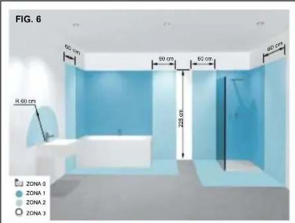
text_image
FIG. 6 60 cm 50 cm 60 cm 80 cm R 90 cm 225 cm ZONA 0 ZONA 1 ZONA 2 ZONA 3FIG. 7A
text_image
AFIG. 7B
text_image
Diagram showing a device panel with circular components and a labeled section B, likely illustrating a mechanical or electrical component.FIG. 8
text_image
1,8 m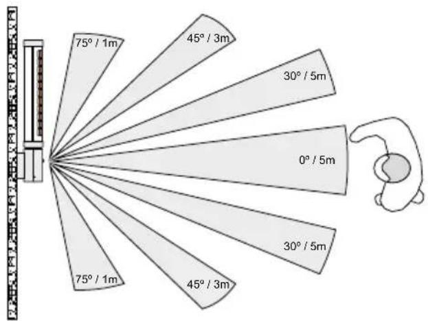
other
| Angle (°) | Value | | --------- | ----- | | 0° | 5 | | 30° | 5 | | 45° | 3 | | 75° | 1 | | 100° | 1 |ESPAÑOL
Please read these instructions thoroughly to avoid damage and hazardous situations. Any use of this heater other than that stipulated in this instruction manual may cause fire, electric shock or injury, and voids all warranties.
Warranty does not apply to any defect, deterioration, loss, injury or damage caused by, or as a result of, the misuse or abuse of this heater. the rights dictated by State law are not prejudiced. None of the terms of this warranty are to be taken as excluding any conditions or warranties implied by State law, which cannot be excluded or modified.
Before any operation remove the packaging and check product integrity. In case of defects or damages do not try to repair it yourself but contact your dealer.
Do not let children play with the packaging and protect the environment by disposing of the packaging in accordance with the national regulations for waste processing.
1. SAFETY WARNINGS
- CAUTION: Some parts of this device may get very hot and cause serious burns. You must be particularly careful when children and vulnerable persons are present.
- Children under 8 years cannot operate the device. Make sure you mount the device so that both the heater itself and the activation cord are out of the reach of children.
- This device can be used by children over 8 years and persons with physical, sensory or mental disabilities or with lack of experience or knowledge if they have been supervised or trained in how to use the device in a safe way, covering the dangers it involves.
• Children must not play with the device. - The cleaning and maintenance to be done by the user must not be done by children.
- NB: This heating device is not fitted with a room temperature control device. Do not use this heating device in small rooms that are occupied by persons who cannot leave the room on their own, unless permanent surveillance is provided.
-
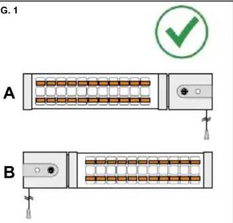
The device must be mounted on a solid vertical wall, placed only in a completely horizontal position (See Fig. 1).
-
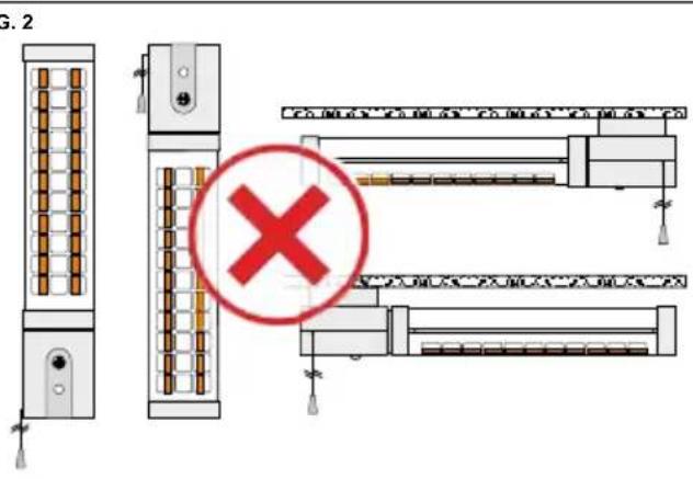
The device can never be installed in the vertical position or directly attached to the ceiling or a similar structure (See Fig. 2).
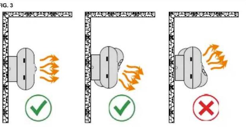
- The device cannot be installed so that it projects heat upwards or towards the ceiling (See Fig. 3).
- The device must not be mounted on an infl ammable surface, like: wood, plastic, carpet, fi ber...etc.
- NB; Once installed, no infl ammable objects or objects affected by heat must be within 2 meters of the device (curtains, towels, plants, pets ... etc.).
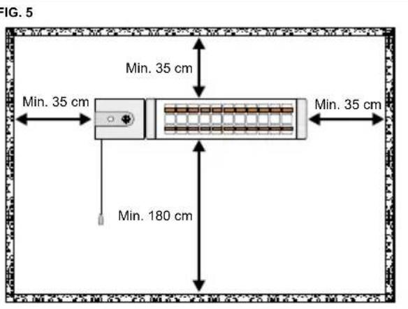
- The device has been designed to be mounted at height and must be installed adhering to the minimum distances from the ceiling, floor and walls or objects to its sides (See Fig. 5).
- Do not install the device right underneath a power socket.
- The safety zones determined in local electrical installation standards, or safety standards applicable in your country must be strictly observed. In any case, if it is installed in a bathroom, never install it in the areas indicated as ZONE 0/1/2. It can be installed in Zone 3 as long as it is placed so that the device is not within reach of anybody who is in the bath or the shower, including the switch activation cord (See Fig. 6).
- The device must not work in rooms or storage spaces with potential dangers owing to the existence of gases from paints, chemical products, detergents, solvents, varnishes, etc., or other highly infl ammable materials.
- After use, we recommend you leave the device to cool for at least 10 to 15 minutes before touching it.
- Before turning the device on for the first time, check that all the package's protective elements have been removed, including the foam for protecting the heater tubes.
- For fixed electrical installation, disconnection means must be incorporated as per the installation regulations, with contact separation in all poles that provide total disconnection under category III overvoltage.
-
If the power cable is damaged, it must be replaced with a cable with the same plug.
-
Make sure that the power cable doesn't touch the hottest parts of the device.
- Don't use the device to dry clothes or towels.
• Device designed for interior use.
2. INSTALLATION
Before installing the device, read all the Safety Warnings indicated in the above section carefully.
- This device can be installed with the control box on the right side (Fig. 1 A) or on the left side (Fig. 1 B). The device is pre-assembled in the factory to be installed with the control box on the right (Fig. 1 A).
If, due to the layout of the washroom you have to install the device with the control box on the left side (Fig. 1 B), proceed as follows:
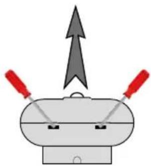
- Remove the front cover with a screwdriver, pressing on the two tabs on the side of the device (See Fig. 4). - Change the route of the cord that operates the rotary switch, so that it comes out through the groove on the other side.
NB: Once installed, the cord must always come out through the groove on the bottom of the control box.
- To increase the sensation of heat from the device, you can orient the head so that it projects the heat more directly towards the floor, in the desired area. The angle of rotation is approximately 30^ (See Fig. 3).
The head's orientation will depend on the installation layout.
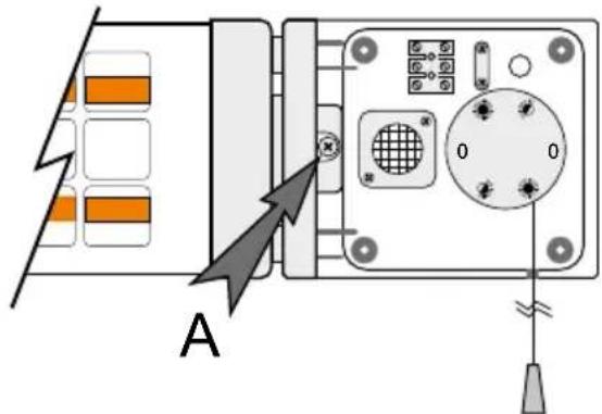
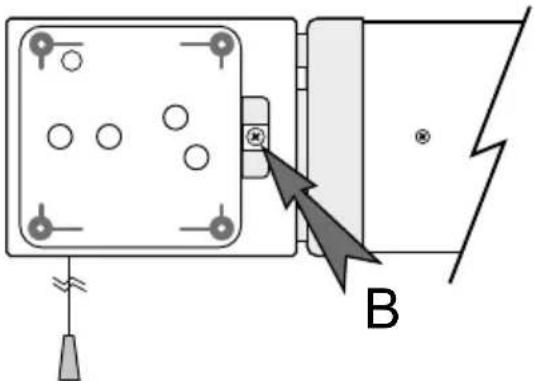
- If you have an installation layout with the control box on the right side (Fig. 1 A) and you want to orient the head by tilting it towards the floor, you must previously remove screw A inside the control box (See Fig. 7A). - If you have an installation layout with the control box on the left side (Fig. 1 B) and you want to turn the head, tilting it towards the floor, you must previously remove screw B inside the control box (See Fig. 7B).
NB: One of the two screws indicated (Figure 7A-7B) must always stay put, never remove both screws.
3. ELECTRICAL CONNECTION AND FIXTURE
NB: Before connecting the device, check that its electricity supply is completely disconnected and read all the Safety Warnings indicated in the corresponding section carefully.
Note: The device comes with a rotary single-pole switch, providing a distance ≥ 3mm between contacts.
- Remove the front cover with a screwdriver, pressing on the two tabs on the side of the device (See Fig. 4).
- Fixed Installation
Insert the fixed installation cables (L-N- ⊕) through the access hole to the inside of the control box. Fasten the cables, passing them through the fixture clamp. Connect the cables to the terminal strip: (L) brown color, (N) Blue color, ⊕ (Yellow-green).
- By means of flexible cable and plug (not supplied)
These must have the following technical specifications:
Type of fl exible cable: H05VV-F 3G x 0.75 mm ^2 / Length less than 2 m.
Plug: 250V AC 16A with 2P + ground connection.
Insert the fl exible cable through the access hole to the inside of the control box. Secure the fl exible cable, fastening it with the fi xture clamp. Connect the fl exible's wires to the terminal strip: (L) brown color, (N) Blue color, ⏻ (Yellow-green).
Break the groove on the rear part of the base to be able to feed the fl exible cable through it and connect it to the corresponding power socket.
- Using the device as a template, mark the position of the four holes on the wall.
Make the 4 holes (diameter 5 mm), insert the rawlplugs and fix the device with the four screws provided.
- Put the front cover back on, making sure that it has been fixed properly by the two side tabs.
4. OPERATION
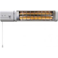
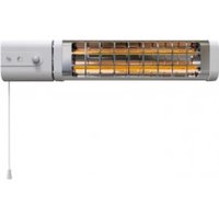
- Pulling the rotary switch cord turns the device on. On the front lens you can see the following symbols. You can change the operating power by pulling successively on the cord, until you turn it off.
| Model | 0 |  |  |
| INFRARED-125 OFF 600 W 1.200 W | |||
| INFRARED-125 OFF 750 W 1.500 W | |||
2. INFRARED-155 model (Figure 8)
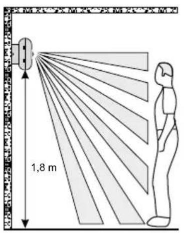
The INFRARED-155 model incorporates a movement sensor to increase the energy saving without diminishing the user's comfort. This system is very useful for public washrooms, changing rooms, gyms and other spaces with constant movement of persons. This sensor automatically controls the activation / deactivation of the device, preventing the heater staying on with no users present.
- By pulling successively on the cord, you can turn the device off/on and select the desired operating power.
- At the instant the sensor doesn't detect any movement inside the room/bathroom, it will start counting. If the sensor doesn't detect any movement after 5 minutes the heater will stop automatically and go into standby mode.
- At the instant movement is detected again within the sensor's area of influence (Figure 8), the heater will turn on again at the pre-selected power.
This model also incorporates an adjustable run-on timer. Independently of the presence sensor, the device will stop after the run-on time set and the user will have to turn the heater on again by pulling the cord. You have the option to deactivate this timer. See the following section.
Setting the run-on timer (Only for the INFRARED-155 model)
NB: Before setting the timer, check that the device's electricity supply is completely disconnected.
- Remove the front cover with a screwdriver, pressing on the two tabs on the side of the device (See Fig. 4).
- Following the below table and using a small screwdriver, you can change the sequence of the two micro-switches on the electronic control board and select the run-on time as desired:
| Position Timer | |
 | Operation without run-on timer (standard setting) |
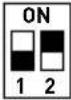 | OFF after 30 minutes |
 | OFF after 60 minutes |
 | OFF after 120 minutes |
5. MAINTENANCE
Before starting any maintenance operation, don't forget to disconnect the device at the mains and let the heater cool down for a few minutes.
This product requires no specific maintenance. It only needs to be cleaned periodically to prevent dust build-up on the lamps, as this could cause the heater to overheat. Clean the lamps with a brush and the product's body with a damp cloth.
The lamps must be replaced by qualified staff, so contact the S&P Official Service Network, for expert technical assistance.
Do not submerge the device or spray it with water.
6. PUTTING OUT OF SERVICE AND RECYCLING
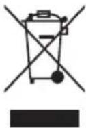
EEC legislation and our consideration of future generations mean that we should always recycle materials where possible; please do not forget to deposit all packaging in the appropriate recycling bins. If your device is also labeled with this symbol, please take it to the nearest Waste Management Plant at the end of its servicable life.
7. DISMANTLING, RECYCLING OR ELIMINATION OF THE PRODUCT AT THE END OF ITS USEFUL LIFE
If the device is scrapped, this must be done in adherence to legal provisions governing the elimination or recycling of materials and components.
List of the heater's main materials:
- Sides and control box in PP plastic.
• Body and front grill in steel.
• Electronic Boards with tin. - Electrical cables.
- Quartz crystal lamps.
8. TECHNICAL ASISTANCE
S&P's large technical Service network will guarantee adequate technical assistance. If a fault is observed in the unit, please contact any of the mentioned technical service offices and they will attend to your problem. Any manipulation of the appliance by personnel not belonging to the Offi cial S&P Services will result in your guarantee being void. For any queries regarding S&P products please contact any branch of our After Sales Service network if you are in Spain, or your regular dealer in the rest of the world.
To find your nearest dealer, visit your website at www.solerpalau.com
FRANÇAIS
S&P's large Technical Service network will guarantee adequate technical assistance. If a fault is observed in the unit, please contact any of the mentioned technical service offices and they will attend to your problem. Any manipulation of the appliance by personnel not belonging to the Official S&P Services will result in your guarantee being void. For any queries regarding S&P products please contact any branch of our After Sales Service network if you are in Spain, or your regular dealer in the rest of the world. To find your nearest dealer, visit our website at www.solerpalau.com