
VMC AKOR ST HR - Frying Pan Soler & Palau - Free user manual and instructions
Find the device manual for free VMC AKOR ST HR Soler & Palau in PDF.
| Product type | Dual-flow ventilation unit |
| Brand | Soler & Palau |
| Model | AKOR ST HR |
| Category | Stove |
| Total weight | 16 kg |
| Disassembled weight | 8.5 kg |
| Power supply | Single-phase 230 V ~ 50 Hz + Earth |
| Recommended electrical protection | Independent 2 A circuit breaker |
| Cable cross-section | 1.5 mm² |
| Ventilation type | Dual-flow with heat exchanger |
| Number of speeds | 2 |
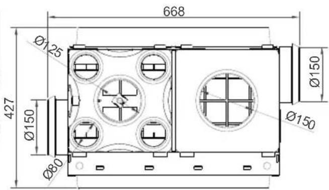
| Connection diameter | Extraction: Ø125 mm (kitchen), Ø80 mm (others); Supply: Ø150/Ø125/Ø125; Fresh air: Ø150 |
| Filters | 2 filters (fresh air and extraction) |
| Maintenance of vents | Every 2 months: clean with warm soapy water |
| Maintenance of filters | Twice a year: dusting or washing with warm soapy water |
| Maintenance of the heat exchanger | Twice a year: vacuum dusting |
| Safety instruction | Cut off the main power before any intervention |
| Warranty | Void in case of unauthorized modification |
| Spare parts | Filters: reference FILTRE X2 AKOR ST/EQUATION (code 600 919) |
| Repairability | Removable components: fan units, panels, heat exchanger |
| Manufacturer | UNELVENT (France) / S&P (Spain) |
Frequently Asked Questions - VMC AKOR ST HR Soler & Palau
User questions about VMC AKOR ST HR Soler & Palau
0 question about this device. Answer the ones you know or ask your own.
Ask a new question about this device
Download the instructions for your Frying Pan in PDF format for free! Find your manual VMC AKOR ST HR - Soler & Palau and take your electronic device back in hand. On this page are published all the documents necessary for the use of your device. VMC AKOR ST HR by Soler & Palau.
USER MANUAL VMC AKOR ST HR Soler & Palau
High Performance heat recovery ventilation unit with balanced supply and extract air flow .p.12
Caisson de VMC double flux Haut Rendement p.21
2.PRODUCT OVERVIEW 13
2.1 Operating principle 13
2.2 Description 14
- INSTALLATION 14
3.1 Dimensions and weight 14
3.2 Handling 15
3.3 Installation 16
- SETTING THE VENTILATION 17
4.1 Kitchen flow control 17
4.2 Adjustment of other wet rooms 17
- ELECTRICAL CONNECTION 18
- START UP 18
- MAINTENANCE 18
7.1 Instructions 18
7.2 Frequency 20
- WASTE MANAGEMENT 20
8.1 Treatment of Packagings and non dangerous wastes 20
8.2 Treatment of a household WEEE 20
1. GENERAL POINTS
1.1Warnings
Your ventilation system is indispensable for the comfort of your home. NEVER TURN OFF YOUR VENTILATION UNIT.
Care should be taken to prevent back flow, inside rooms, of gas from the exhaust pipe of gas appliances or other open fire installations.
Do not operate the ventilation unit during sanding operations in the home: danger of rapid and irreversible fouling of the various elements of the apparatus: filters, heat exchanger, fans.
Installation and maintenance of this equipment must be performed by a person with ability to apply these instructions.
According to EN60335-1 §7.2 :
This appliance can be used by children aged from 8 years and above and persons with reduced physical, sensory or mental capabilities or lack of experience and knowledge if they have been given supervision or instruction concerning use of the appliance in a safe way and understand
the hazards involved. Children shall not play with the appliance.
Cleaning and user maintenance shall not be made by children without supervision.
1.2 Safety information
Disconnect power at the main circuit breaker and ensure that no one can unintentionally turn it on again.
1.3 Reception - Storage
Each unit is carefully inspected before shipping. The unit should be stored protected from exterior weather conditions, impacts and dirt of any kind during transport and on site before installation.
1.4 Warranty
Any removal or addition of material in the unit, and any intervention on the original wiring is not permitted without prior permission, and could result in the withdrawal of approvals and the warranty. The unit must be used according to manufacturer's specifications, otherwise the function it fulfils could be compromised.
The following are not covered by the warranty: defects due to abnormal use non-compliant with the recommendations of our manuals, defects due to normal wear, incidents caused by the negligence or lack of supervision or maintenance, defects due to the improper installation of the equipment or poor storage conditions before installation.
Under no circumstances is the manufacturer responsible for equipment that is altered, repaired or removed, even partially.
2.PRODUCT OVERVIEW
2.1 Operating principle
Your dual flow ventilation unit ensures the exchange of air in your home by exhaust inlets located in wet rooms such as: the kitchen, bathroom, toilet, etc. Fresh air is supplied mechanically by the same ventilation unit to living rooms: lounge, bedrooms, etc.
A heat exchanger in the ventilation unit recovers the heat carried by the exhaust air which is used to preheat the fresh air entering the unit. This unit saves energy and ensures improved thermal and acoustic comfort.
Your ventilation unit has two operating speeds:
- 1st speed: provides a normal airflow ventilation rate
- 2nd speed: allows for a peak flow in the kitchen to remove pollutants during meal preparation (rapid extraction of water vapor, fumes, odors, etc.)
These two speeds are controlled by a switch we recommend is located in the kitchen.
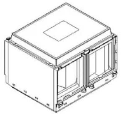
2.2 Description
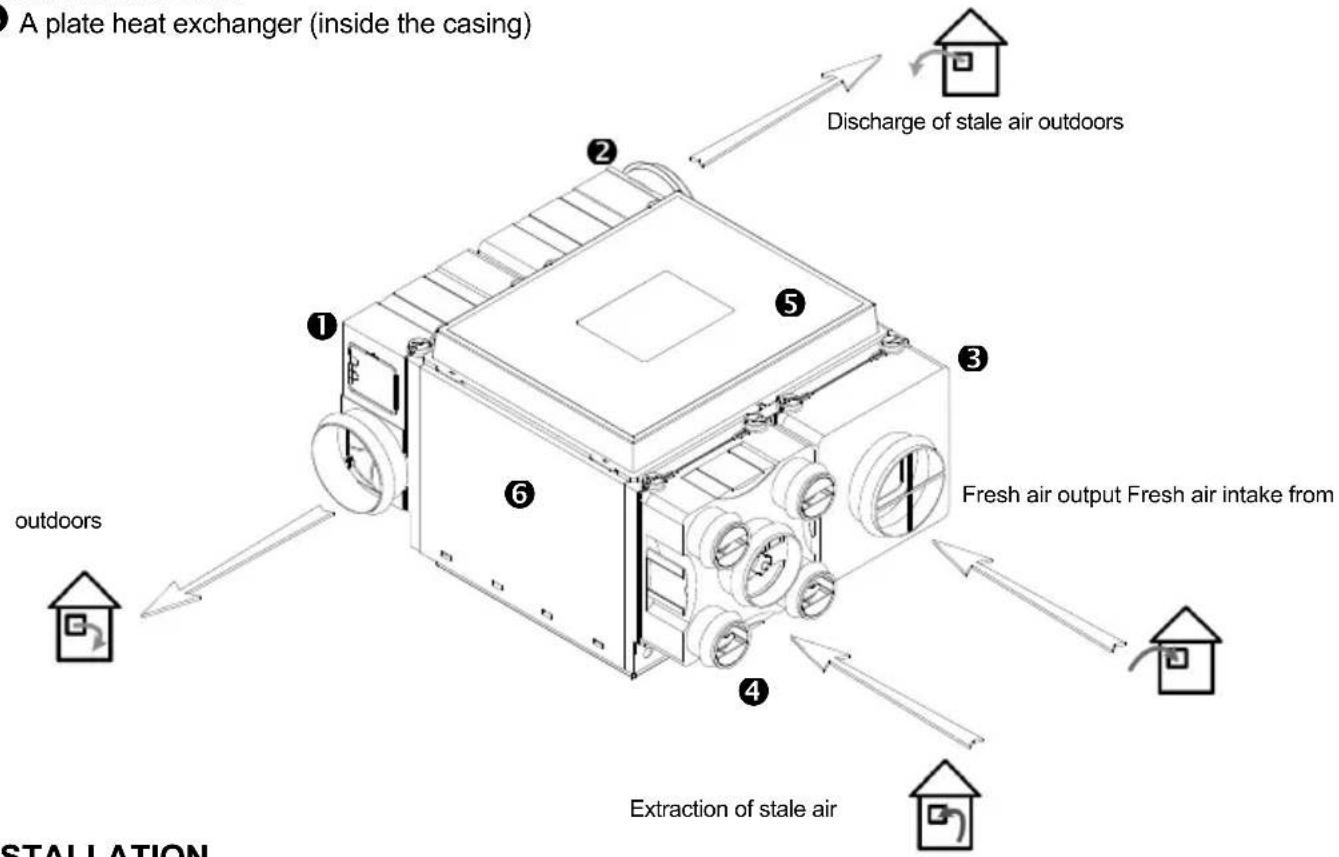
Your dual flow ventilation unit consists of:
A fresh air input unit
An air extraction unit
A fresh air side with 0150 nozzle equipped with a filter
An extraction side with a 125 nozzle and 4 80 nozzles also equipped with a filter
A removable cover
A plate heat exchanger (inside the casing)
3. INSTALLATION
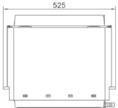
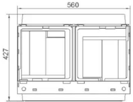
3.1 Dimensions and weight
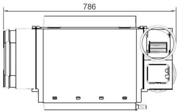
Weight: 16 kg
Note: The unit can be easily disassembled to facilitate handling and to pass it through small access hatches: see §3.2 Handling
Weight : 8,5 kg
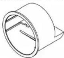
3.2 Handling
To facilitate handling, or passage through a narrow hatch, it is possible to separate the different elements of the dual flow unit:
- Fan group
- Stale air extraction and fresh air face
- Exchanger chamber
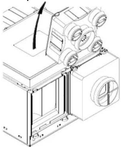
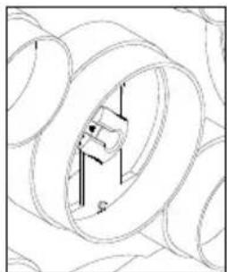
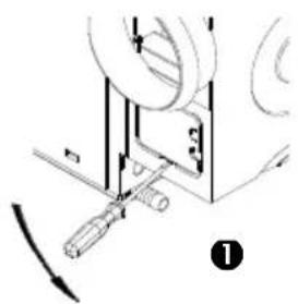
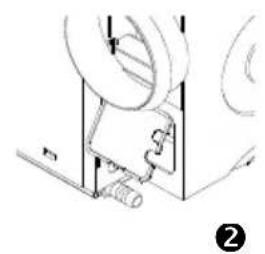
3.2.1 Disassembly the fan units
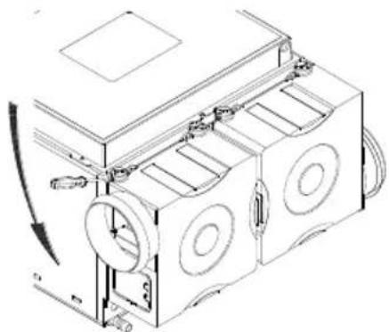
using a flat screwdriver (4mm), remove the clips,
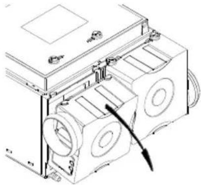
slightly tilt the fan unit
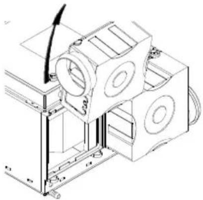
then lift it upwards
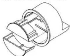
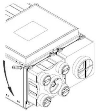
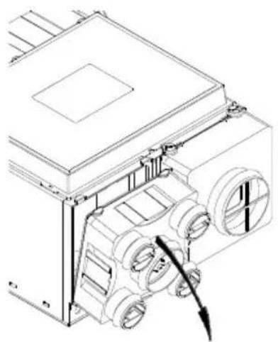
3.2.2 Disassembly of the stale air exhaust and fresh air and fresh air output faces
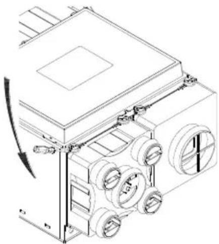
U using a flat screwdriver (4mm), remove the clips,
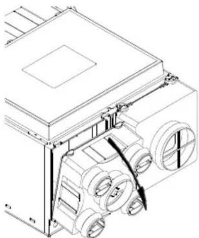
slightly tilt the extraction face with the filter,
then raise it with the filter upwards,
4
Do the same for the fresh air intake.
3.3 Installation
3.3.1 Ventilation unit
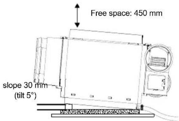
The unit is designed to be installed in a suitable cupbaord or in the attic. The unit must be installed horizontally and then at a slope of about 5irc (slope height 30 mm ) so that condensation can drain through the drain placed on the side of the unit (see diagram opposite).
It is advisable to place the unit on a piece of foam or glass wool to prevent noise transmission.
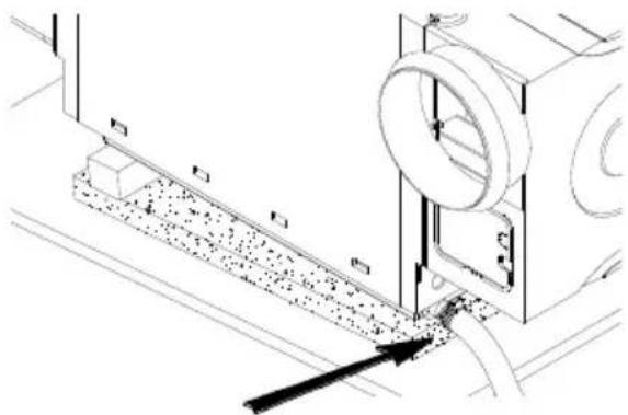
Do not forget to connect the drain to a 19mm internal diameter pipe connected to the waste water network: install the pipe with a regular slope, without any high points, to facilitate the flow of condensate and insulate the pipe to prevent frost.
Use a clamp to adjust the hose to the drain.

Ensure a clearance of 450mm above the group in order to remove the heat exchanger during maintenance operations.
3.3.2 Extraction and air output system
The network is made of insulated PVC flexible duct and must be as simple as possible:
- Avoid unnecessary lengths and bends
Use large radius bends
The duct should never be crushed
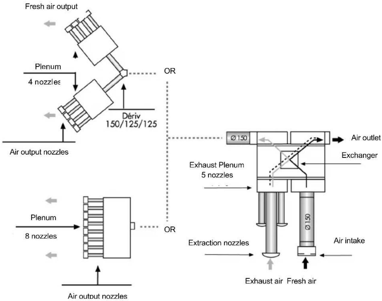
The extraction network consists of 0125mm duct for the kitchen and 80 other damp areas.
The exhaust of the extraction group is connected to a roof output by a 0150 duct.
The fresh air output network is built using a 0150/0125/0125 distribution unit (not supplied) and two 4-nozzle 080 splitters (supplied)
The fresh air output is made from 0150 duct.
IMPORTANT TIP: Insulate the network with a layer of glass wool (70 mm) to improve network insulation and insulate the dual flow unit similarly.
4. SETTING THE VENTILATION
4.1 Kitchen flow control
The kitchen vent is connected to the 0125mm nozzle of the extraction plate.
| Type of housing | Setting the kitchen flap lever |
| T2/3 | Position 3 |
| T4 | Position 4 |
| T5 y + | Position 5/+ |
4.2 Adjustment of other wet rooms
Wet room vents are connected to the 080 mm nozzles on the face extraction
According to the housing regulations, flows are:
| T3 to T7 housing | |
| Room(s) with bath or shower 30 m3/h | |
| Single WC 30 m3/h | |
| Multiple WC 15 m3/h | |
| Other wet rooms: laundry... 15 m3/h |
Regulator set at 15m3 /h
Regulator set at 30m3 /h
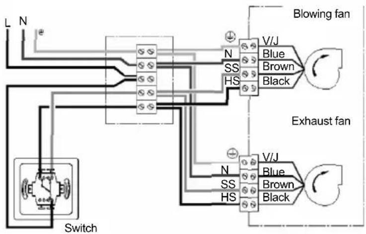
5. ELECTRICAL CONNECTION
Before any operation, disconnect power at the main circuit breaker and ensure that no one can unintentionally turn it on again.
The electrical connection must be completed according to the diagram shown opposite:
Plan for:
- An all-pole switch with a contact opening distance of at least 3mm
- An 2A circuit breaker on the General Distribution Panel for Electrical Safety.
Use cable of 1.5mm2 section and the sheath diameter 16mm.
To access the terminal block of each fan unit, open the electrical hatch using a screwdriver (4 mm) as shown opposite:
6. START UP
Alimentation MONO 230V 50Hz + Ground
Before starting the equipment after installation, ensure that both fans turn freely and that there is no foreign body (such as pieces of insulation, etc.) that may block the rotation of the turbine.
Check that the ducts were not crushed during installation: crushed ducting dramatically reduces ventilation rates and performance.
Ensure the condensate drain is connected properly and that the pipe is insulated to prevent freezing.
7. MAINTENANCE
7.1 Instructions
7.1.1 Extraction and air output nozzles
Clean the bathroom and kitchen exhaust vents with warm water and soap. Remove dust from the air output vents in the main rooms.
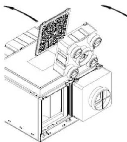
7.1.2 Filters
using a flat screwdriver (4mm), remove the clips,
slightly tilt the extraction face with the filter,
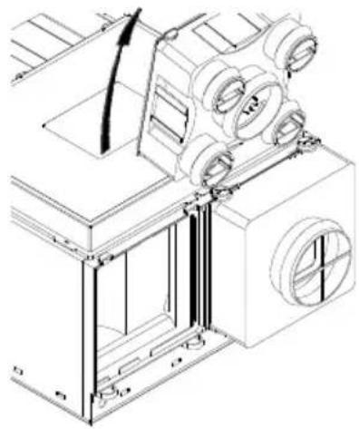
then raise it with the filter upwards,
4 Remove the filter holder,
unclip the filter holder to release the filter,
Do the same for the fresh air intake.
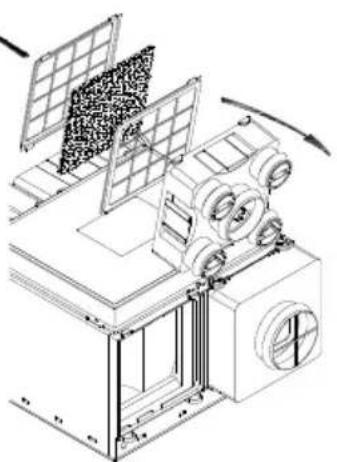
Dust off the filters with a brush or vacuum cleaner.
Filters can also be cleaned in warm soapy water. Allow them to dry completely before putting them back into the unit.
7.1.3 Exchanger
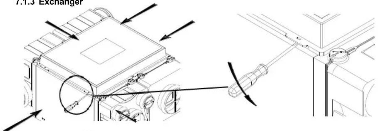
1 Release the 6 attachment points as shown in the diagram above.
Note : To avoid breaking the cover, fully release the 6 fixing points before lifting the cover.
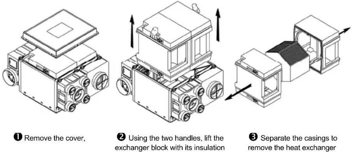
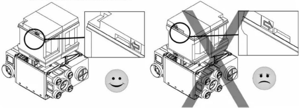
The heat exchanger is fragile, do not handle it by the airflow channels. Remove dust from the exchanger with a vacuum cleaner. Do not use a brush which may introduce dust into the exchanger and thus the air passage channels. When reassembling, reposition the exchanger unit making sure the arrows on the insulation are absolutely directed at the fan units.
7.2 Frequency
| Elements | Maintenance frequency |
| Extraction and air output nozzles Every 2 | months |
| Filters Every 6 months | |
| Heat exchanger Every 6 months |
8. WASTE MANAGEMENT
8.1 Treatment of Packagings and non dangerous wastes
The packagings (unconsigned pallets, cartons, films, wooden boxes) and other non dangerous wastes must be made reusable by an approved service provider. It is strictly prohibited to burn, bury or dump them in nature.
8.2 Treatment of a household WEEE
This product must not be dumped or treated with household refuse, but must be deposited in an appropriate collection point for waste electrical and electronic equipment (WEEE).
2. PRESENTATION PRODUIT

- GENERAL POINTS
- 1.1Warnings
- the hazards involved. Children shall not play with the appliance.
- Cleaning and user maintenance shall not be made by children without supervision.
- Safety information
- Reception - Storage
- Warranty
- 2.PRODUCT OVERVIEW
- Operating principle
- Description
- INSTALLATION
- Dimensions and weight
- Handling
- Disassembly the fan units
- Disassembly of the stale air exhaust and fresh air and fresh air output faces
- Installation
- Ventilation unit
- Extraction and air output system
- SETTING THE VENTILATION
- Kitchen flow control
- Adjustment of other wet rooms
- ELECTRICAL CONNECTION
- Plan for:
- START UP
- MAINTENANCE
- Instructions
- Extraction and air output nozzles
- Filters
- Exchanger
- Frequency
- WASTE MANAGEMENT
- Treatment of Packagings and non dangerous wastes
- Treatment of a household WEEE
- PRESENTATION PRODUIT
Brand : Soler & Palau
Model : VMC AKOR ST HR
Category : Frying Pan