
appLS06OMNI - Barcode scanners Aqprox - Free user manual and instructions
Find the device manual for free appLS06OMNI Aqprox in PDF.


| Product Type | Omnidirectional laser barcode scanner |
| Brand | Aqprox |
| Model | appLS06OMNI |
| Scanning Technology | Omnidirectional laser |
| Usage | Fixed (platform) or portable |
| Power Supply | USB (5V) or power adapter (not included) |
| Dimensions (approx.) | 10 x 10 x 5 cm |
| Weight (approx.) | 300 g |
| Connectivity | USB cable |
| Configuration | By reading dedicated barcodes |
| Factory reset | Yes, via 'Reset' barcode |
| Version display | Yes, via barcode |
| Maintenance | Soft dry cloth |
| Safety | Do not open, avoid any liquid |
| Recycling | Compliant with WEEE directive (2002/96/EC) |
| Spare parts | Contact manufacturer |
Frequently Asked Questions - appLS06OMNI Aqprox
User questions about appLS06OMNI Aqprox
0 question about this device. Answer the ones you know or ask your own.
Ask a new question about this device
Download the instructions for your Barcode scanners in PDF format for free! Find your manual appLS06OMNI - Aqprox and take your electronic device back in hand. On this page are published all the documents necessary for the use of your device. appLS06OMNI by Aqprox.
USER MANUAL appLS06OMNI Aqprox
Omnidirectional Barcode Scanner
appLS06OMNI

natural_image
Red diagonal line pointing downward to the right (no text or symbols)
natural_image
Solid red circular shape with no text or symbols
pie
| Category | Value | |---|---| | Red Circle | 100 |User Guide

natural_image
Red diagonal line on white background (no text or symbols)1. Introducción
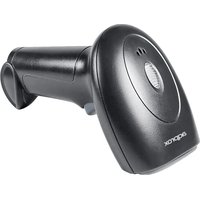
The scanning platform is high efficiency omnidirectional laser barcode scanning platform. Not only the shape is small and exquisite but also the property is stable and reliable. No matter how the POS environment it can do. Can be used as a fixed scanning platform, also be used as a handheld scanning platform.
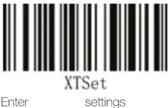
2. Enter the settings
Reading the “enter” barcode allows the reading engine to turn on the function of configuring the specific barcode (setting code function). After the function is turned on, the reading engine can be modified by reading one or more setting codes.
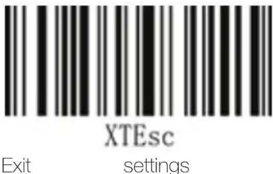
3. Exit settings
After reading the “Exit Settings” barcode, the reading engine will exit the status of reading the setting code and save the previous settings. In this state, only the specifics such as “Enable Setting Code” and “Restore Factory Default” can be read and processed. Setup code.
4. Restore the factory settings
Note: Please use the "Restore Factory Default" function carefully. After reading this setting code, the current parameter setting will be lost and
replaced with the factory default value.
The factory default parameters and functions can be found in the default settings table in the appendix.
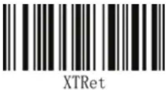
Reset
5. Display the version number
After reading the "display version number" barcode, the version information of the device can be output.

Display version number
6. Prompt tone
After the reading engine successfully reads, it can output a PWM signal to drive the external buzzer circuit to make a sound. The sound signal can be turned off or allowed to be output by setting, and the type and volume of the sound can be modified by setting. The corresponding settings can be made with the following setting codes.
a. Turn on/off the tone
Note: The bar code is silent when the sound is turned off, but there is an audible prompt when reading the setup code.

**Open the sound Turn off the sound

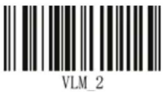
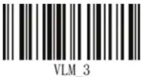
b. Volume setting
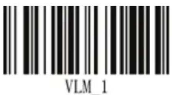
**Volume 1 (maximum) Volume 2
Volume 3
- LED light tips

**LED light on LED light off

8. Read settings
a. Automatic scan mode
In the automatic scan mode, the reading engine performs continuous reading operations.

**Automatic scanning
b. Button trigger scan mode
In the button trigger scan mode, you need to press the button to control whether the reading engine starts working.

Key trigger scan
c. Laser scanning mode
The basic working principle of the laser scanner is: the scanner emits a beam of light through a laser diode, and reflects it on the surface of the bar code. After the light is reflected by the bar or the air, it returns to the reader and is converted into an electrical signal by the photoelectric converter. Or the decoding software on the terminal performs decoding. We can set the light from the device to a single-line or multi-line scan mode according to your needs.

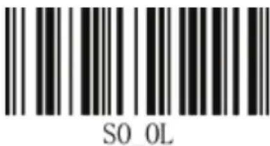
**Multi-line scanning mode Single line scan mode
d. Code recognition setting
With the code recognition setting, you can quickly turn on the identification of all code systems and restore the default recognition options for all code systems.
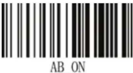
Open all code recognition
9. System sleep settings
When the system maintains a state of no key or no communication, it can enter a sleep state with low power consumption.
a.Turn off sleep

**Close sleep
b. Set the sleep time

10 minutes of sleep
20 minutes of sleep

30 minutes of sleep
10. User settings
a. Save as user settings
Users can save their favorite settings as user settings, which will clear the previous user settings.

Save as user settings
b. Restore user settings
After restoring the factory settings, scan the "Restore User Settings" to restore the device to the saved user settings.

Restore user settings
c. Clear user settings (equivalent to restoring factory settings)

Clear user settings
d. Display user version
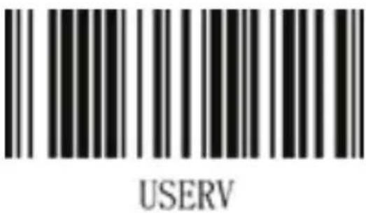
Display user version
e. User version settings Set the user version to V1.0.0
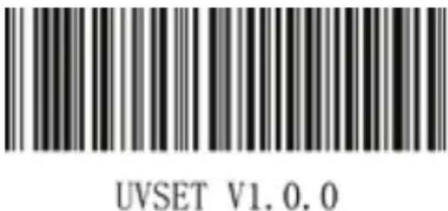
User version is set to V1.0.0
f. User version editing
The user version can be edited by the user. When editing the user version, the character length is limited to 1\~15.
For example: Edit the user version to V1.0.1, the steps are as follows:
- Go to Settings - Read "User Version Editing"
- Read the data codes "V", "1", "", "0", "", "1" (see Appendix F "O-127-digit ASCII code")
- Exit settings

User version editing
11. Transmission mode setting
There are four transmission modes of this device: keyboard (PS2) transmission, serial transmission, USB transmission, and virtual serial transmission. The keyboard (PS2) transmission mode needs to first pass the device through the scan setting code, set to the keyboard (PS2) transmission, and then power off, and the PC end is turned off and restarted before it can be used normally.
Serial port transmission must use the RS-232 serial communication interface to connect to the device, and can only output data in the serial port assistant. When set to serial port transmission, you can choose whether to enable hardware flow control according to your needs. At the same time, the serial port assistant also needs to choose whether to enable the hardware flow control "RTS/CTS". When the settings of the device and the serial port assistant are consistent, the data can be transmitted normally. The USB transfer mode completely simulates the keyboard output, and any data input can be directly output from the keyboard.
The virtual serial port is a USB serial port transmission mode after connecting the device through USB. After setting it as a virtual serial port, you need to set the port as a virtual serial port in the serial port assistant to use the virtual serial port function normally. (The port name of the virtual serial port can be used in the device. Found in the manager's port, which is "Virtual Com Port").
When the setting of the data transmission mode does not match the port actually connected, the device will recognize it after the first reading, and confirm that the data transmission is incorrect for 3 seconds and then sound an alarm tone.
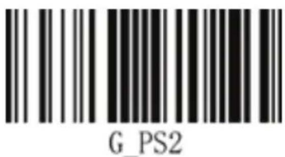
Keyboard (PS2) transmission

Serial transmission
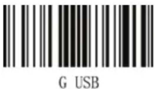
**USB transfer Virtual serial port transmission
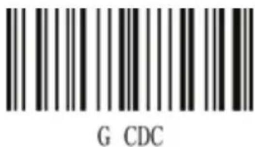
(baud
rate
9600)
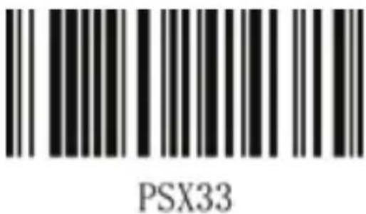
12. Keyboard layout
The keyboard keys corresponding to different national languages are arranged, and the symbols are not the same. The reading engine can be virtualized into keyboard systems of different countries as needed.

**US keyboard British keyboard
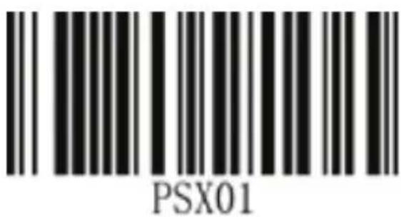

Belgian keyboard Czech-Y keyboard
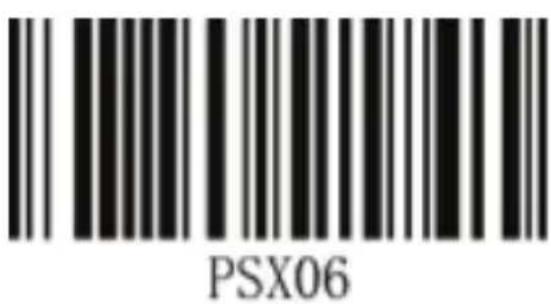
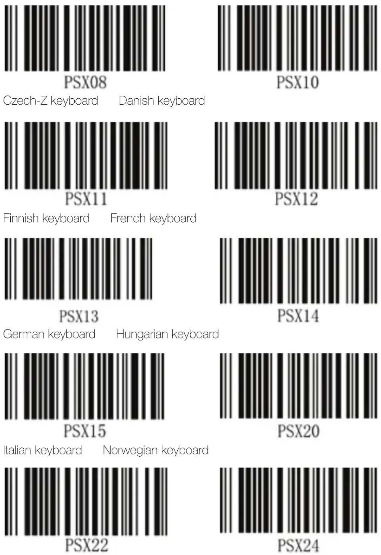
Portuguese keyboard Slovenian keyboard

Spanish keyboard Swedish keyboard


Swiss (French) keyboard Universal keyboard


Turkey-Q keyboard Turkey-F keyboard

Japanese keyboard
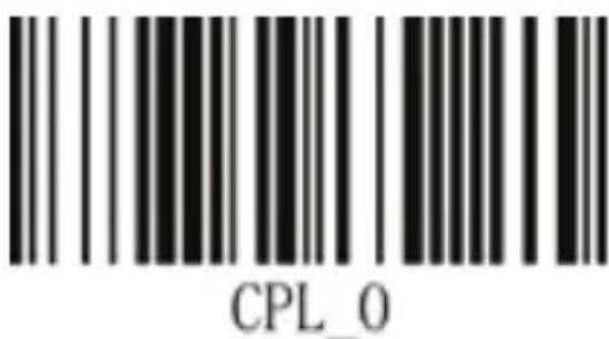
13. CapsLock Key Function Control

** CapsLock key does not affect data output
CapsLock key affects data output
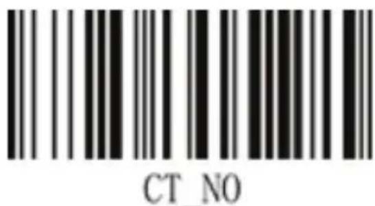
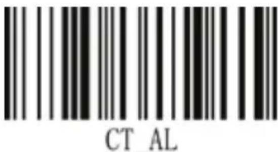
14. Force letter case conversion
This setting allows you to force the case of the read engine virtual keyboard letters to be locked.
** case does not convert Uppercase and lowercase


All uppercase All lowercase
15. Data terminator
The terminator is used to mark the end of a complete piece of data information and is used to indicate the complete end of a data output.

Close data terminator

**Open the carriage return terminator

Turn on the ESC terminator

Turn on the STX terminator

Open ETX terminator

Open TAB terminator

Open line break terminator

Open carriage return + line feed end

Open space terminator
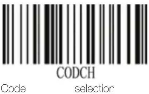
16. Code selection
After selecting a code system, the related operations of all editing systems are only valid on the barcode of the code system. The default setting is all selection.
Setting method: enter the setting - read "code system selection" - select the corresponding code system identity characters - exit the settings.
Cancel method: enter the setting - read "code system selection" - exit the setting, then you can cancel all previous selections.
(Code ID characters are shown in Appendix D - check our website)
17. Prefix/suffix settings
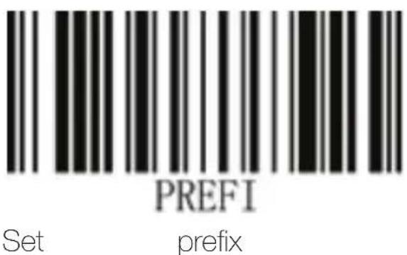
Prefix settings:
Go to Settings - Read "Set Prefix" - Read Content (can be full ASCII, up to 10 digits) - Exit Settings
Prefix cancel:
Go to Settings - read "Set Prefix" - Exit Settings
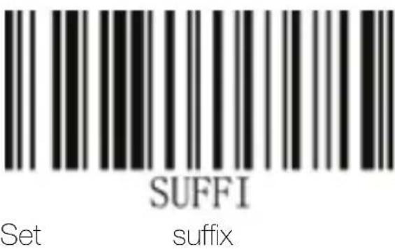
Suffix settings:
Enter settings - read "set suffix" - read content (can be full ASCII, up to 10 digits) - exit settings
Suffix canceled:
Enter settings - read "set suffix" - exit settings
** Check our website www.approxtpv.es for advanced user guide.
18. Safety, maintenance and recycling instructions
- Caution: Never open the device, the internal parts are danger, electrical shock.
- Do not install this unit near water, for example, in a wet basement, in an unprotected outdoor installation or in any area classified as a wet.
- Do not insert objects of any kind into this unit through openings as they may touch voltage points and short out parts that could result in fire or electric shock.
- Do not spill any liquid on the unit. Danger of explosion!
- Do not crush power cables, danger of short circuit!
- Always connect to the manufacturer's recommended tension.
- Clean the product with a soft and dry cloth.
- Follow local regulations for disposing of the product.
19. Recycled
AEE REI-RAEE 5548 In this manual, the container (bin) symbol indicates that the product is subject to the European directive 2002/96 / EC, electrical and electronic products, batteries, and batteries and other accessories must necessarily be subject to a selective collection.
At the end of the life of the device, make use of the recycling bins. This gesture Will help reduce the health risks and preserve the environment.
Municipalities and distributors, Will provide essential details on recycling your old device. If this device carries an internal battery, it must be removed and deposited separately for proper management.

1. Brève introduction




- Omnidirectional Barcode Scanner
- Introducción
- Enter the settings
- Exit settings
- Restore the factory settings
- Display the version number
- Prompt tone
- Read settings
- b. Button trigger scan mode
- c. Laser scanning mode
- d. Code recognition setting
- System sleep settings
- User settings
- Transmission mode setting
- Keyboard layout
- CapsLock Key Function Control
- Force letter case conversion
- Data terminator
- Code selection
- Prefix/suffix settings
- Safety, maintenance and recycling instructions
- Recycled
- Brève introduction
Brand : Aqprox
Model : appLS06OMNI
Category : Barcode scanners