
48-22-8586 - Storage box MILWAUKEE - Free user manual and instructions
Find the device manual for free 48-22-8586 MILWAUKEE in PDF.

| Product Type | Steel Storage Cabinet |
| Brand | Milwaukee |
| Model | 48-22-8586 |
| Total Capacity | 907 kg (2,000 lbs) |
| Shelf Capacity | 68 kg (150 lbs) |
| Door Storage Bin Capacity | 9 kg (20 lbs) |
| Casters | 4 swivel casters with brake, 127 mm (5") diameter |
| Locking | Central key lock |
| Reversible door | Yes, can be opened left or right |
| Tip-over prevention | Wall anchor cable included |
| Connectivity | Compatible with other Milwaukee steel storage units |
| Material | Steel with powder coating |
| Included accessories | 3 door bins, 4 shelves, 1 magnetic power strip holder, 1 key, 4 rubber bumpers, mounting hardware |
| Maintenance | Grease casters annually; clean with glass cleaner |
| Warranty | 3 years (material and workmanship defects) |
Frequently Asked Questions - 48-22-8586 MILWAUKEE
User questions about 48-22-8586 MILWAUKEE
0 question about this device. Answer the ones you know or ask your own.
Ask a new question about this device
Download the instructions for your Storage box in PDF format for free! Find your manual 48-22-8586 - MILWAUKEE and take your electronic device back in hand. On this page are published all the documents necessary for the use of your device. 48-22-8586 by MILWAUKEE.
USER MANUAL 48-22-8586 MILWAUKEE
natural_image
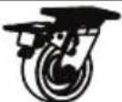
Line drawing of a Milwaukee industrial machine with wheels and wheels (no text or symbols on the device itself)Cat. No. / No de cat.
48-22-8586
27" HIGH CAPACITY STEEL LOCKER
CASIER EN ACIER HAUTE CAPACITÉ DE 69,2 CM (27")
CASILLERO DE ACERO DE GRAN CAPACIDAD DE 69,2 CM (27")
WARNING To reduce the risk of injury, user must read and understand operator's manual.
IMPORTANT SAFETY INSTRUCTIONS
WARNING
Read all safety warnings and all instructions. Failure to follow the warnings and instructions may result in serious injury. Save all warnings and instructions for future reference.
- Use the product in accordance with these instructions and in the manner intended, taking into account the working conditions. Use of the product for operations different from those intended could result in a hazardous situation.
- Keep work area clean and well lit. Cluttered or dark areas invite accidents.
- Fully assemble the product according to the assembly instructions. Do not leave off any pieces.
- Do not modify the product in any way. Use only specifically recommended accessories. Drilling holes or modifying the product will lower the load capacity, which can cause the product to collapse, resulting in injury.
- Lock wheels when product is not being moved. Unlocked wheels can allow the product to move unexpectedly.
- Keep the product on a level surface. Do not load, unload, or park product on an incline. The product may become unbalanced and tip, resulting in injury.
•Always balance the product load to avoid tipping. Unbalanced products are more likely to tip when being moved or when using the product work surfaces. Evenly distribute the weight front to back and side to side. To help prevent the product from tipping, load the product starting at the bottom.
- Do not exceed the maximum product weight, including contents. Do not exceed the maximum weight for each drawer. Overloaded products can tip, collapse, or damage drawer slides.
- Keep children and bystanders away while loading, unloading, and moving the product. Distractions can cause you to lose control.
- Only lift the product according to the instructions in this manual. Other methods may be dangerous, resulting in injury.
- Only transport the product when empty. Properly secure when transporting.
- Do not mount the product on a truck bed or any other moving object.
- Lock door before rolling the product. The door could come open and make the product unstable and tip.
- Secure all items before rolling the product. Loose items could shift, causing the product to become unstable.
- Do not use shelves as steps. Do not stand on the product. Product may tip, causing injury.
- Do not step on shelves. Shelf may collapse or break. Product may tip, causing injury.
- Do not use product in explosive atmospheres, such as in the presence of flammable liquids, gases or dust. This equipment has internal arcing or sparking parts. Product should not be located in a recessed area or below floor level.
- Maintain product. Check for misalignment or binding wheels, breakage or bending of shelves or other parts and any other condition that may affect the product's operation. Do not use damaged product.
- Maintain labels and nameplates. These carry important information. If unreadable or missing, contact a MILWAUKEE service facility for a free replacement.
- Have your product serviced by a qualified repair person using only identical replacement parts. This will ensure that the safety of the product is maintained.
SYMBOLOGY

Warning

Read Operator's Manual

Do not open more than one drawer at a Chest/cabinet may tip, causing injury.
Lock wheels when chest/cabinet is not being moved. Unlocked wheels can allow the locker to move unexpectedly.

Do not use drawers as steps. Chest/et may tip, causing injury.

Lock both the lid and all drawers before g the chest/cabinet.

Tether free standing locker to wall. r may tip, causing injury.
FUNCTIONAL DESCRIPTION
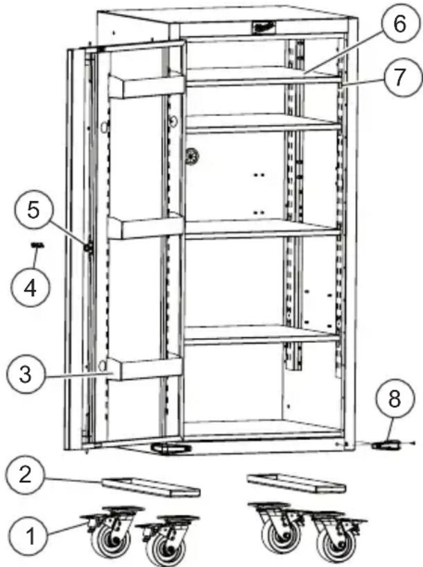
- 5" Swivel caster
- Caster riser plate*
- Door storage bin
-
Key
-
Lock
- Shelf
- Shelf mounting clip
- Bumper
*Install casters with riser plates when locker is connecting to MILWAUKEE storage which use 6" x 2" casters.
SPECIFICATIONS
Cat. No. 48-22-8586
Shelf Capacity 150 lbs. (68 kg)
Door Storage Bins Capacity ......20 lbs. (9 kg)
Total Capacity 2000 lbs. (907 kg)
ASSEMBLY
CAUTION
Be sure to follow the assembly instructions for the appropriate
locker. Do not use power tools to assemble locker. Tighten bolts with hand wrenches.
Tools Required

Phillips
screwdriver
Safety glasses
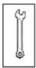
10 mm Wrench
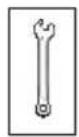
13 mm Wrench
Hardware Included
NOTE: Items not shown to actual size.
| Hardware Item Description Quantity | |||
| AA | 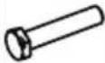 | BoltM8 x 40 mm | 16 |
| BB |  | Steel washer19 x 8.5 x 2 mm | 16 |
| CC | 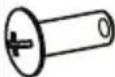 | Screw BoltM6 x 16 mm | 8 |
| DD |  | Steel washer18 x 6.5 x 1 mm | 8 |
| EE |  | BoltM6 x 24 mm | 2 |
| FF |  | Steel washer16 x 8 x 1.2 mm | 4 |
| GG |  | Screw boltM4 x 16 mm | 8 |
| HH |  | Screw boltM4 x 12 mm | 4 |
| II | 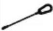 | Anti-tip cable 2 | |
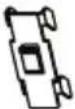
| JJ |  | Wall bracket 2 | |
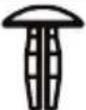
| KK |  | ScrewST5.5 x 70 mm | 4 |
| LL |  | Wrench 1 | |
| Item Description Quantity | ||
 | Door storage bin 3 | |
 | Shelf 4 | |
 | Cord bracket 2 | |
 | Caster riser plate(only for use when connecting to storage unit that has 6" casters) | 2 |
 | 5" x 2" swivel caster | 4 |
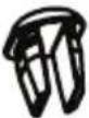 | Red plastic plug | 5 |
 | Red plastic plug | 5 |
 | Shelf clip 16 | |
 | Magnetic holder for power strip(power strip not included) | 1 |
 | Rubber bumper | 4 |
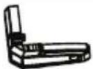
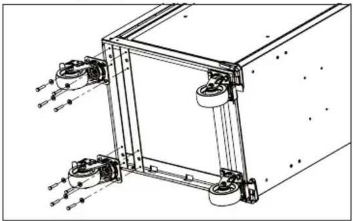
Installing the Casters
CAUTION
Two people may be required to complete installation.
- Lay the locker on its back. Use the packaging material to protect the finish.
- Mount the four swivel casters with brake using four bolts (AA) and washers (BB) per caster. NOTE: When locker is connecting to MILWAUKEE storage which use 6" x 2" casters, install casters with riser plates.
- Tighten all bolts securely with a wrench.
- Return the locker to its upright position.
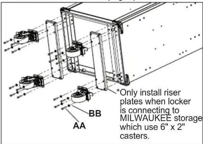
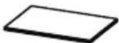
Installing the Bumpers
Attach the bumpers using two screws (GG) per bumper. Do not overtighten the screws.
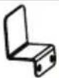
Installing the Shelves
For each shelf, place four shelf mounting clips, with the clips facing upward, at level height into the locker mounting rail slots. Insert shelf into locker (1) and fully seat onto shelf mounting clips (2).
Installing Magnetic Holder for Power Strip
Place magnetic holder in desired location while considering cord management.
Power strip is not included. When connecting the Locker to the right side of an existing MILWAUKEE steel storage unit, the power strip must be removed from the storage unit and can be placed into the magnetic holder included with Locker.
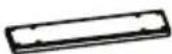
Installing Cord Bracket
Install cord brackets in desired location using two bolts (HH) per bracket while considering cord management.

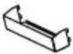
Installing Door Storage Bins
Place each bin into the door mounting rail slots at the desired level height.
natural_image
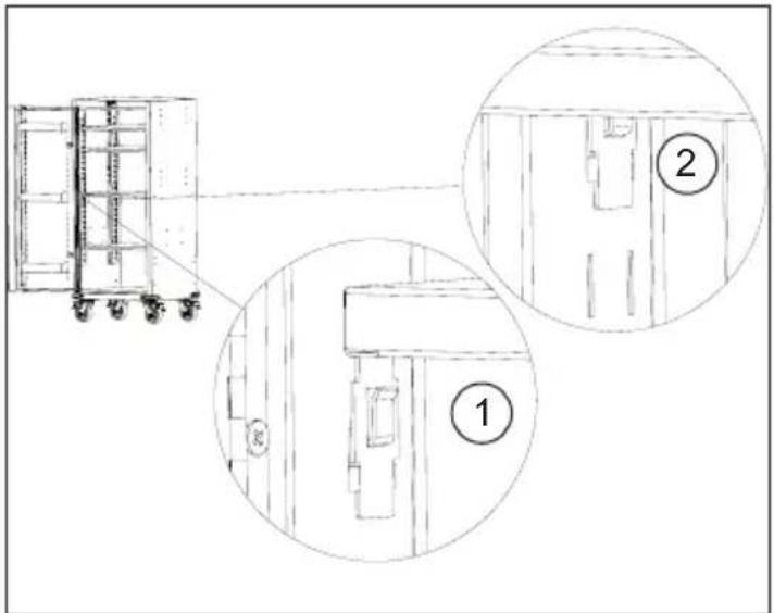
Technical line drawing of a wheeled storage unit with an inset close-up showing internal components (no text or symbols)Reversing the Locker Door
CAUTION Two people may be required to complete installation.
The Locker Door is reversible to accommodate both left and right side orientations.
- Remove door storage bins from door interior.
- Remove door from locker by removing the screws in the hinge. Flip door and resinstall hinge on right side.
- Remove logo plate and the two black plastic plugs, flip, and reinstall.
- Remove lock cylinder, flip, and reinstall.
- Reinstall storage bins.
natural_image
Technical line drawing of two modular shelving units with doors open, showing front and side views (no text or symbols)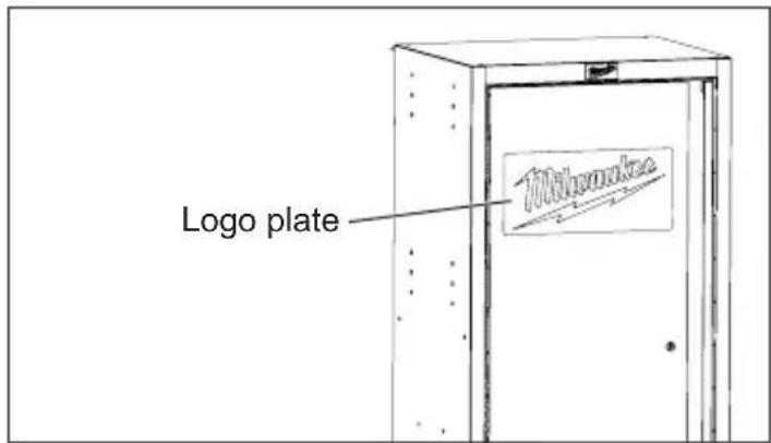
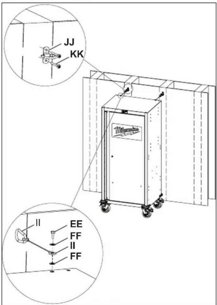
Installing the Wall Tether
WARNING When locker is used as a stand-alone unit, it must be properly secured to a wall using the included wall tether cables. Failure to properly secure with the wall tether may be hazardous, resulting in injury or property damage. The locker must be secure into a minimum of 2 wall studs using the hardware provided. Failure to do so may allow the locker to become unstable and tip. Do NOT attach using drywall anchors. If anchoring into masonry, use appropriate masonry anchors (not included).
Secure free standing locker to wall using provided wall tether hardware.
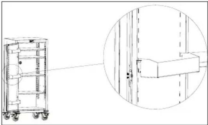
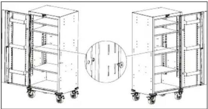
Connecting to Compatible MILWAUKEE Steel Storage
AWARNING Only connect to compatible MILWAUKEE steel storage. Modifying the locker to accept other steel storage may be hazardous, resulting in injury or property damage.
When connected, the locker must be flush with the adjoining storage unit; to accomplish this two of the locker's swivel casters will be removed during installation. Leaving the casters on will interfere with the overall caster function of the system.
ACAUTION Two people are required to complete installation. This step must be performed on level ground to prevent tipping or injury.
The MILWAUKEE Locker can be connected to select MILWAUKEE Chest/Cabinet and Mobile Work Stations. Depending upon your model, the connection steps may vary. For a complete listing of accessories, go online to www.milwaukeetool.com or contact a distributor.
NOTE: When locker is connecting to MILWAUKEE storage which use 6" x 2" casters, install casters with riser plates (See "Installing the Casters").
- Determine which end of the adjoining storage unit the locker will be connected to. NOTE: The Locker Door is reversible to accommodate both left and right side orientations. See "Reversing the Locker Door".
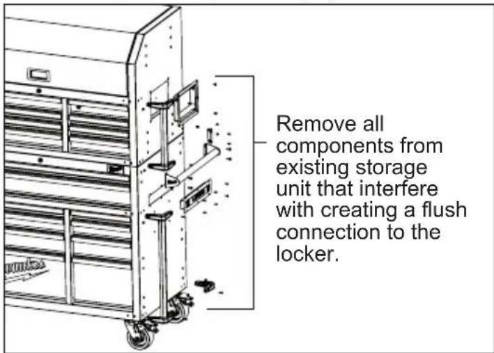
- Remove all components from the outside of the adjoining storage unit that will interfere in creating a flush connection to the locker (such as bumpers, corner extrusions, lift handles, side handles, brackets, chargers, and power strips).
- Remove the contents, shelves, shelf mounting clips, and door storage bins from the locker.
-
Remove all components from the outside of the locker unit that will interfere in creating a flush connection to the adjoining storage unit (such as bumpers and chargers).
-
Lay the locker on its back. Use the packaging material to protect the finish.
- Remove the two swivel casters that will be nearest to the adjoining storage unit.
natural_image
Technical line drawing of a mechanical assembly with mounting brackets and mounting holes (no text or symbols)- Place foam block adjacent to the bottom edge of the existing MILWAUKEE cabinet.
- Lock caster wheels on the Locker as unlocked wheels will cause a tipping hazard.
- Lift the Locker upright and set on top of the foam block. Locker should be stationary.
- Gently roll the existing MILWAUKEE cabinet directly adjacent to the upright Locker and align the attachment holes per diagram. This should create a flush connection.
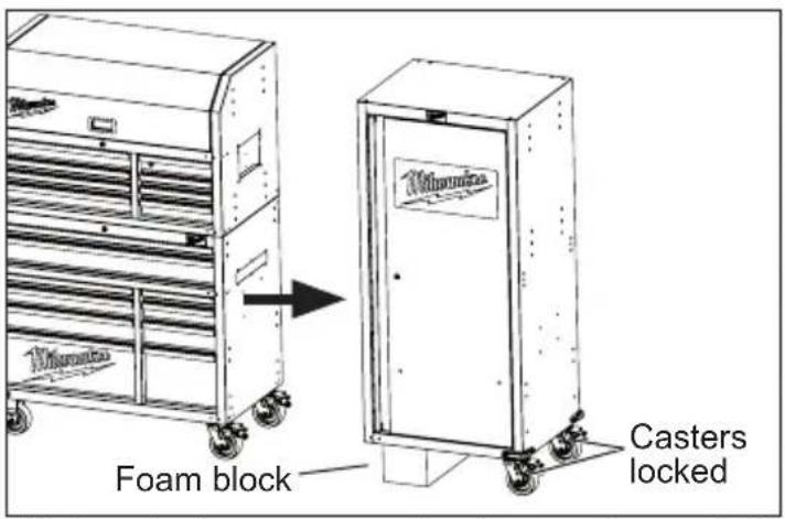
- Lock the caster wheels on the existing MILWAUKEE tool storage cabinet.
- Connect the locker to the adjoining MILWAUKEE cabinet using eight bolts (CC) and washers (DD) through the interior mounting rail slots of the locker into the adjoining storage unit. Space bolts evenly across the lower, mid, and upper sections of the locker as shown for the best connection. Tighten all bolts securely with a wrench.
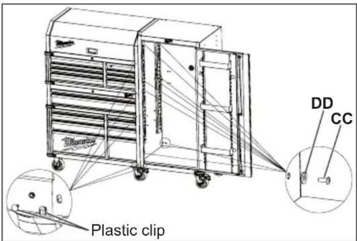
- Insert the red plastic plugs into the exposed press nut holes on the front of the storage unit and locker. Match the shape of the plug to correspond to the shape of the hole.
OPERATION
⚠WARNING To avoid injury or property damage, do not exceed maximum shelf capacity. Use care when moving the locker on incline or rough surface. Locker may tip if weight is not evenly distributed front to back and side to side. Place more than half the total load weight on the bottom shelves when possible.
Locking and Unlocking the Locker
Insert the key. Turn it fully left to lock, or fully right to unlock. Always remove the key after locking and unlocking.
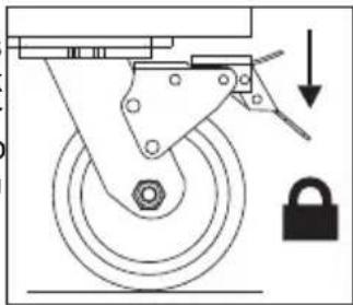
Using the Caster Brakes
To lock the swivel casters, step down on the levers marked ON. Be sure to lock all casters to prevent locker from rolling or swiveling. To unlock casters, push down on the levers marked OFF.
natural_image
Mechanical diagram showing a wheel assembly with a lock and directional arrow (no text or symbols)Moving the Locker on an Incline or Rough Surface
Take care that the locker does not tip or become unbalanced when moving it on an incline or rough surface. Do not exceed an incline of 10 degrees. Lock the locker and secure all items before moving.
Rolling the Locker
The locker is only intended for rolling short distances. Do not modify the locker in any way. Drilling holes or modifying the locker will lower the load capacity, which can cause the locker to collapse, resulting in injury. Lock the locker and secure all items before rolling.
Lifting the Locker
The locker is not intended to be lifted. However, if you need to lift, empty the locker and then place straps or forks inside and next to casters. Do not lift loaded lockers. Never lift by the side handle. Be sure all bystanders are moved away before lifting locker.
MAINTENANCE
WARNING To reduce the risk of injury, contact MILWAUKEE Corporate After Sales
Service Technical Support for ALL repairs and replacement parts.
Maintaining the Locker
Keep your locker in good repair by adopting a regular maintenance program. Before use, examine the general condition of your locker. Check for loose screws, misalignment, binding of wheels, broken parts and any other condition that may affect its safe operation. Do not use a damaged locker.
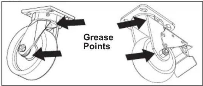
Maintaining the Casters
Grease the casters annually using high quality bearing grease.
Cleaning
This steel locker has been coated with industrial powder coating for a durable finish. To help protect the powder coated finish, do not allow harsh chemicals (oil, grease or other chemical) to remain on the powder coating surface. Use a glass cleaner to clean and maintain all surfaces of powder coating.
Keep the locker handles and wheels clean, dry and free of oil or grease. Use only mild soap and a damp cloth to clean your locker since certain cleaning agents and solvents are harmful to plastics. Some of these include: gasoline, turpentine, lacquer thinner, chlorinated cleaning solvents, ammonia and household detergents containing ammonia. Never use flammable or combustible solvents around locker.
Service
For service and repair information, including the ordering of service parts, call our Corporate After Sales Service Technical Support line at 1-800-SAWDUST, or visit our website at www.milwaukeeetool.com.
ACCESSORIES
WARNING Modifying the locker to accept other accessories may be hazardous, resulting in injury or property damage. Use only specifically recommended accessories according to the manufacturer's instructions.
For a complete listing of accessories, go online to www.milwaukeetool.com or contact a distributor.
SERVICE - UNITED STATES
1-800-SAWDUST (1.800.729.3878)
Monday-Friday, 7:00 AM - 6:30 PM CST
or visit www.milwaukeetool.com
Contact Corporate After Sales Service Technical Support with technical, service/repair, or warranty questions.
Email: metproductsupport@milwaukeeetool.com
Become a Heavy Duty Club Member at www.milwaukeetool.com to receive important notifications regarding your tool purchases.
SERVICE - CANADA
Milwaukee Tool (Canada) Ltd 1.800.268.4015
Monday-Friday, 7:00 AM - 4:30 PM CST or visit www.milwaukeetool.ca
LIMITED WARRANTY USA & CANADA
Every MILWAUKEE steel storage chest and cabinet are warranted to the original purchaser only to be free from defects in material and workmanship. Subject to certain exceptions, MILWAUKEE will repair or replace any part on a chest or cabinet which, after examination, is determined by MILWAUKEE to be defective in material or workmanship for a period of three (3) years after the date of purchase. Return of the chest or cabinet to the place of purchase is required. A copy of the proof of purchase should be included with the return product. This warranty does not apply to damage that MILWAUKEE determines to be from repairs made or attempted by anyone other than MILWAUKEE authorized personnel, misuse, alterations, abuse, normal wear and tear, lack of maintenance, or accidents.
Warranty Registration is not necessary to obtain the applicable warranty on a MILWAUKEE steel storage chest or cabinet. The manufacturing date of the product will be used to determine the warranty period if no proof of purchase is provided at the time warranty service is requested. If you feel your product has a warranty defect, or if you need information on a service/replacement part, please contact MILWAUKEE at 1.800.SAWDUST (1.800.729.3878) for instructions.
ACCEPTANCE OF THE EXCLUSIVE REPAIR AND REPLACEMENT REMEDIES DESCRIBED HEREIN IS A CONDITION OF THE CONTRACT FOR THE PURCHASE OF EVERY MILWAUKEE PRODUCT. IF YOU DO NOT AGREE TO THIS CONDITION, YOU SHOULD NOT PURCHASE THE PRODUCT. IN NO EVENT SHALL MILWAUKEE BE LIABLE FOR ANY INCIDENTAL, SPECIAL, CONSEQUENTIAL OR PUNITIVE DAMAGES, OR FOR ANY COSTS, ATTORNEY FEES, EXPENSES, LOSSES OR DELAYS ALLEGED TO BE AS A CONSEQUENCE OF ANY DAMAGE TO, FAILURE OF, OR DEFECT IN ANY PRODUCT INCLUDING, BUT NOT LIMITED TO, ANY CLAIMS FOR LOSS OF PROFITS. SOME STATES DO NOT ALLOW THE EXCLUSION OR LIMITATION OF INCIDENTAL OR CONSEQUENTIAL DAMAGES, SO THE ABOVE LIMITATION OR EXCLUSION MAY NOT APPLY TO YOU. THIS WARRANTY IS EXCLUSIVE AND IN LIEU OF ALL OTHER EXPRESS WARRANTIES, WRITTEN OR ORAL. TO THE EXTENT PERMITTED BY LAW, MILWAUKEE DISCLAIMS ANY IMPLIED WARRANTIES, INCLUDING WITHOUT LIMITATION ANY IMPLIED WARRANTY OF MERCHANTABILITY OR FITNESS FOR A PARTICULAR USE OR PURPOSE; TO THE EXTENT SUCH DISCLAIMER IS NOT PERMITTED BY LAW, SUCH IMPLIED WARRANTIES ARE LIMITED TO THE DURATION OF THE APPLICABLE EXPRESS WARRANTY AS DESCRIBED ABOVE. SOME STATES DO NOT ALLOW LIMITATIONS ON HOW LONG AN IMPLIED WARRANTY LASTS, SO THE ABOVE LIMITATION MAY NOT APPLY TO YOU, THIS WARRANTY GIVES YOU SPECIFIC LEGAL RIGHTS, AND YOU MAY ALSO HAVE OTHER RIGHTS WHICH VARY FROM STATE TO STATE. This warranty applies to product sold in the U.S.A. and Canada only. Please consult the 'Find a Service Center Search' in the Parts & Service section of MILWAUKEE's website www.milwaukeeetool.com or call 1.800.SAWDUST (1.800.729.3878) to locate your nearest MILWAUKEE factory Service Center location.
INSTRUCTIONS IMPORTANTES CONCERNANT LA SECURITE
AVERTISSEMENT
natural_image
Four types of mechanical tools and fixtures: screwdriver, safety goggles, wrench, and wrench (no text or symbols)natural_image
Technical line drawing of a mechanical cabinet with an inset close-up showing its side view (no text or symbols)natural_image
Technical line drawing of two multi-compartment server racks with open doors, showing front and side views (no text or symbols)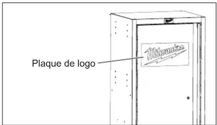
Mise-en-place du support de montage mural
natural_image
Technical line drawing of a multi-level industrial machine with wheels and control panels (no text or symbols)natural_image
Technical line drawing of a mechanical assembly with mounting brackets and mounting holes (no text or symbols)Milwaukee Tool (Canada) Ltd
1.800.268.4015
Monday-Friday, 7:00 AM - 4:30 PM CST
www.milwaukeetool.ca
GARANTIE LIMITÉE -
AUX ÉTATS-UNIS ET AU CANADA
Cat. No....48-22-8586
natural_image
Technical line drawing of a rack-mounted storage unit with an inset close-up showing its side view (no text or symbols)natural_image
Technical line drawing of two multi-cartment shelving units with wheels, showing front and side views (no text or symbols)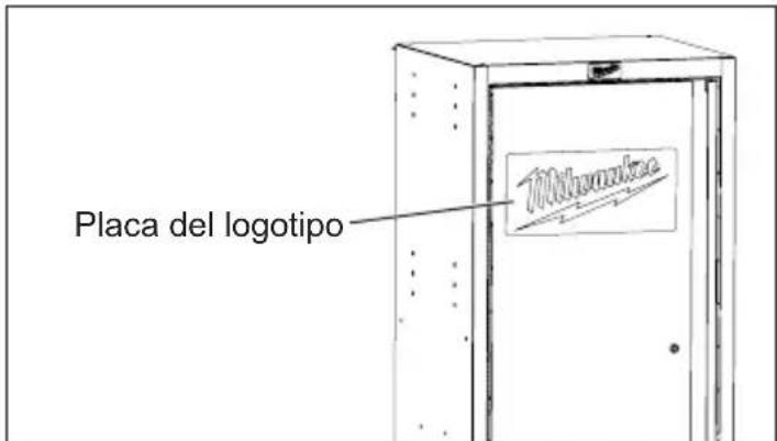
natural_image
Technical line drawing of a mechanical assembly with mounting brackets and mounting holes (no text or symbols)natural_image
Mechanical diagram showing a wheel with a lock and directional arrow (no text or symbols)Lunes a Viernes (9am a 6pm)
13135 West Lisbon Road
Brookfield, WI 53005 USA