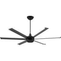
Turbo6 - Fan Big Ass Fans - Free user manual and instructions
Find the device manual for free Turbo6 Big Ass Fans in PDF.


| Product type | Ceiling fan |
| Brand | Big Ass Fans |
| Model | Turbo6 |
| Input voltage | 100-277 VAC, 1 Φ, 50/60 Hz |
| Weight (by model) | 11.1 kg to 12.8 kg |
| Number of blades | 6 |
| Blade material | Composite |
| Control | Remote control included, Big Ass Fans mobile app |
| Special features | Kick Ass mode (overspeed), automatic speed adjustment, fan grouping |
| Outdoor use | Rated for covered outdoor locations (damp) |
| Installation | Mounting on outlet box, concrete ceiling, wood joist; extension rod included |
| Safety | Safety cable, circuit breaker shutdown |
| Maintenance | Regular dusting, cleaning with a soft cloth - no solvents |
| Annual check | Safety cable, screws, wiring |
| Spare parts | Contact customer service; blades are sold as a set |
| Compatibility | Do not use with a dimmer or third-party switch |
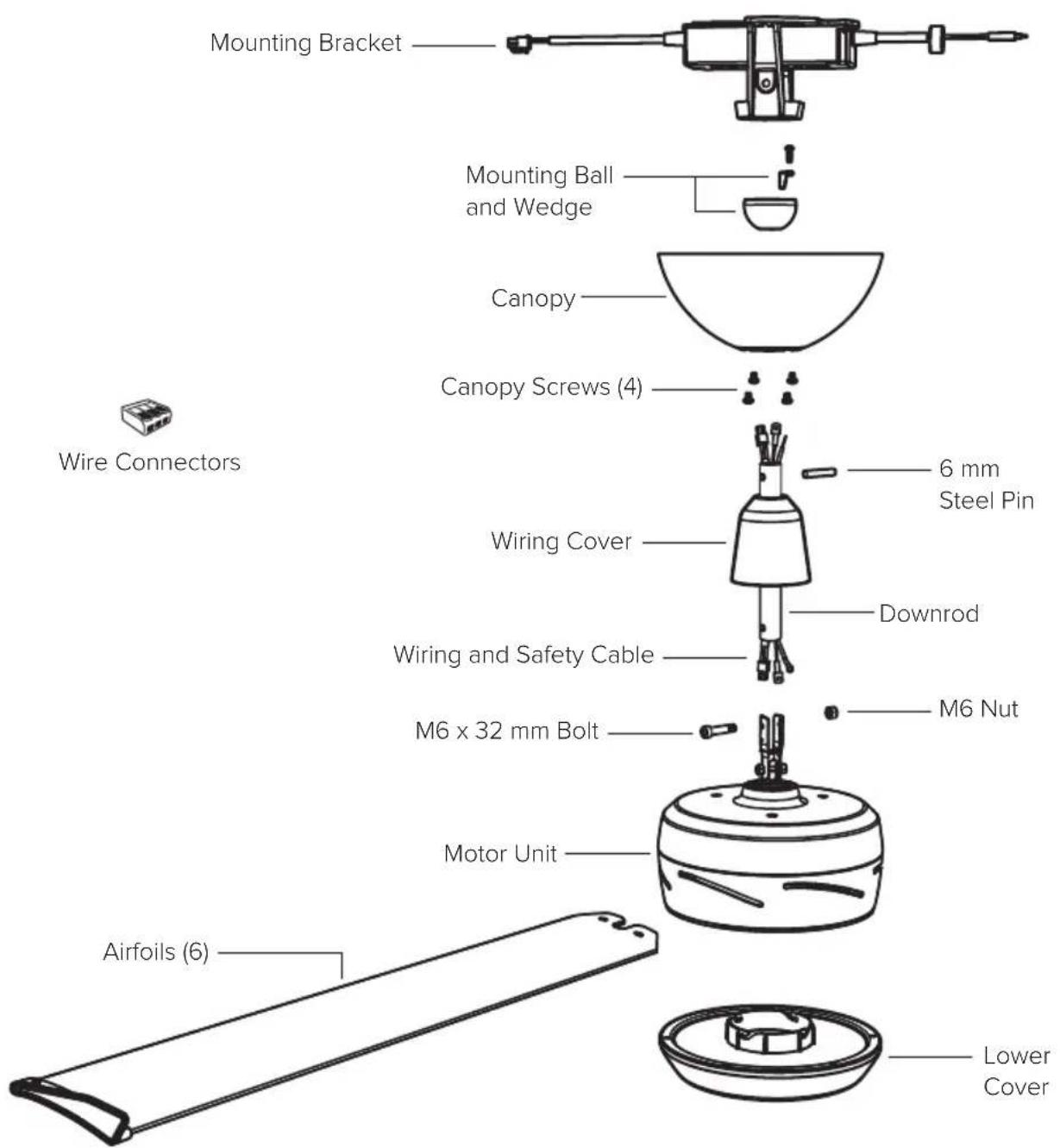
| Box contents | Motor block, 6 blades, extension rod, ball joint, bracket, remote control, screws, wire cover, covers |
| Warranty | Visit bigassfans.com |
Frequently Asked Questions - Turbo6 Big Ass Fans
User questions about Turbo6 Big Ass Fans
0 question about this device. Answer the ones you know or ask your own.
Ask a new question about this device
Download the instructions for your Fan in PDF format for free! Find your manual Turbo6 - Big Ass Fans and take your electronic device back in hand. On this page are published all the documents necessary for the use of your device. Turbo6 by Big Ass Fans.
USER MANUAL Turbo6 Big Ass Fans
natural_image
Line drawing of a six-petal ceiling fan with a top-mounted head (no text or symbols)BIG ASS FANS® TURBO6
Installation Guide
Before You Start ....1
Parts and Hardware....3
Fan Installation....4
Troubleshooting 18
Maintenance....20
Contact Us 21

Rev. B
07/25/2024
READ AND SAVE THESE INSTRUCTIONS

√ Turn off Power at Breaker
Input Voltage: 100–277 VAC, 1 Φ, 50/60 Hz
Do not connect the fan to a damaged power source. Do not attempt to resolve electrical failures on your own. Contact a licensed electrician if you are uncomfortable performing electrical work. A licensed electrician must install the fan if required by local code.
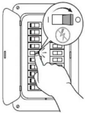
Do not use the fan with a dimmer switch or a third-party switch.
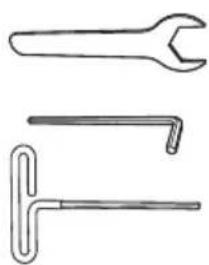
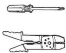
☑ Gather Tools
natural_image
Three types of wrenches shown in line drawings: a straight wrench, a long handle with a flanged end, and a T-shaped tool (no text or symbols)Provided with fan
natural_image
Two types of electrical crimping tools shown in line drawings (no text or labels)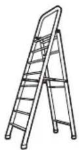
natural_image
Line drawing of a ladder with six legs, no text or symbols present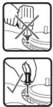
natural_image
Two-step diagram showing a hand using a tool to mark a cross symbol, with no text or labels present.√ Prepare Fan Site and Gather Hardware
Outlet Box: Make sure your outlet box is suitable for fan support. If there is not an outlet box at the fan location, install one on a ceiling joist or beam. You will need to supply two 10-32 screws for attaching the fan mounting bracket to the outlet box.
Concrete Ceiling: You will need to supply three anchor bolts* for attaching the fan mounting bracket to the ceiling. If required by your local building and safety codes, you will also need to supply an anchor hook* for the safety cable. See page 2 for hardware specifications and installation details.
Wood Ceiling Joist: You will need to supply two corrosion-resistant 12-11 x 45 mm hex head timber screws with seal for attaching the fan mounting bracket directly to the joist. If required by local code, mount or embed an outlet box into the joist. The outlet box must be suitable for fan support.
Covered Outdoor Locations: Damp-rated fans installed in covered outdoor locations must have fixed/permanent full overhead coverage extending at least 2 ft (0.6 m) out from the airfoil tips on all sides. Damp-rated fans installed in covered outdoor locations can be mounted to flat ceilings only.
Models and Maximum Weight: MK-TRB1-052306: 24.5 lb (11.1 kg), MK-TRB1-062306: 26.4 lb (12 kg), MK-TRB1-072306: 28.2 lb (12.8 kg)
☑ Prepare Concrete Ceiling (if applicable)
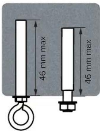
Drill three ∅ 8 mm holes in the pattern shown. The hole depth should not exceed 46 mm. Remove any dust from the holes. Insert three anchor bolts into the holes. Strike the heads of the anchor bolts with a hammer, ensuring the bolt sleeves are flush with the ceiling surface. Position the mounting bracket on the anchor bolts. Ensure all three anchor bolts are fully tightened to expand and lock the anchors.
If required by local building and safety codes, install an anchor hook for the safety cable. Drill an ∅ 8 mm hole for the anchor hook. The hole depth should not exceed 46 mm. Remove any dust from the hole, and then insert the anchor hook and fully tighten.
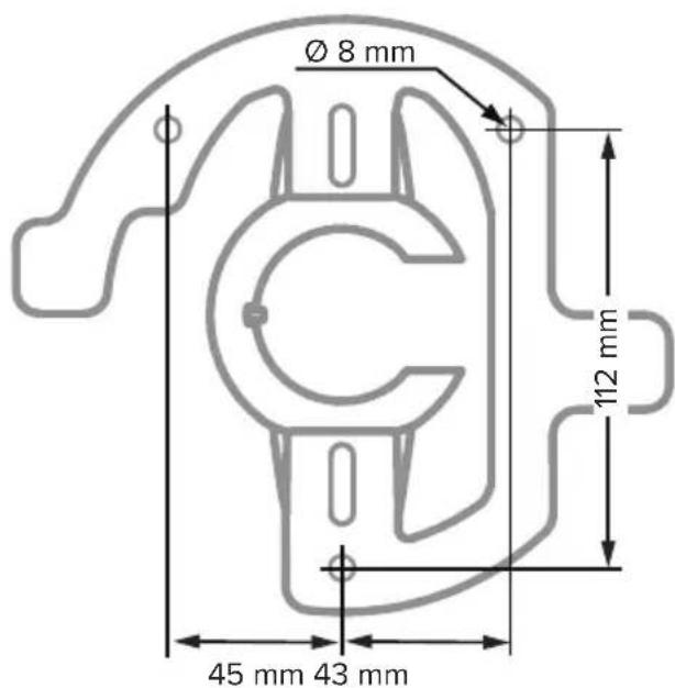
If the EMI filter (not shown) is included, install it with your fan.
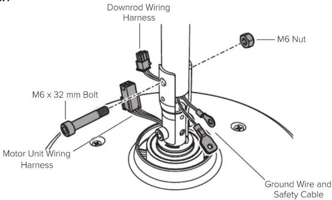
1. Install downrod
Align holes on downrod with holes on motor bracket. Position downrod wiring harness so that it is on the same side of the motor shaft as the motor unit wiring harness. Position ground wire and safety cable so that they are on the opposite side of the motor shaft as the motor unit wiring harness. Secure downrod with the M6 x 32 mm bolt and M6 nut (Fig. 1.1).
Fig. 1.1
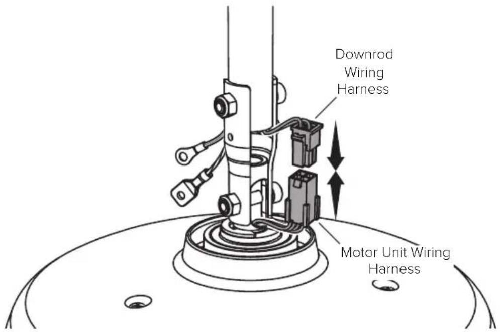
Connect downrod wiring harness to motor unit wiring harness (Fig. 1.2).
Fig. 1.2
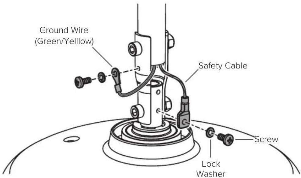
2. Install lower safety cable and ground wire
Install safety cable and ground wire lugs with unpainted screws and lock washers (Fig. 2).
Fig. 2
3. Reduce slack
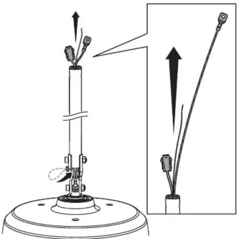
Make sure all hardware is secure, and then gently tug cables at top of downrod to reduce slack (Fig. 3). Make sure rubber plug at top of downrod stays in place.
Fig. 3
natural_image
Technical diagram of a mechanical device with two components and directional arrows indicating motion (no text or symbols)4. Position wiring cover and canopy
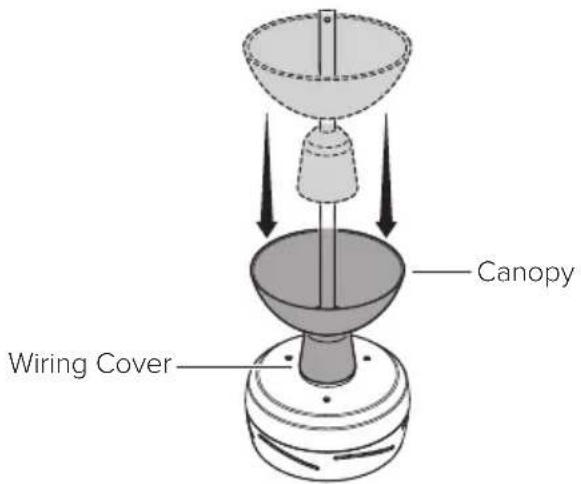
Slide wiring cover down the downrod, resting it on the fan hub. Make sure no wires are visible between the cover and fan hub. Slide canopy down the downrod, resting it on the wiring cover (Fig. 4).
Fig. 4
5. Install mounting ball
Slide mounting ball over downrod (Fig. 5.1).
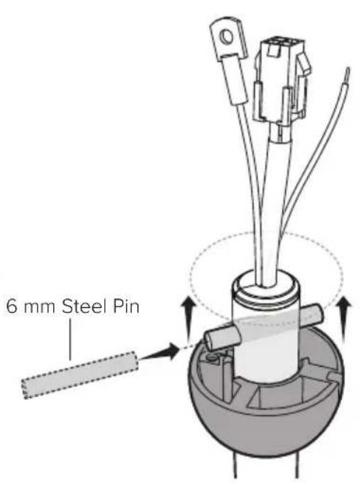
Insert 6 mm steel pin into hole at top of downrod, and then slide the mounting ball upward, seating the steel pin in the inner slots (Fig. 5.2).
Insert wedge into mounting ball and secure with screw. Tighten screw enough to prevent movement between the mounting ball and downrod, but do not over-tighten (Fig. 5.3). Make sure rubber plug at top of downrod is still in place.
Fig. 5.1
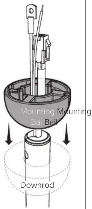
Fig. 5.2 Fig. 5.3

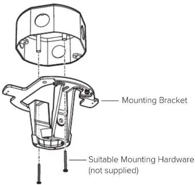
6. Install mounting bracket
Disconnect power to fan location before installing mounting bracket.
WARNING: Mount only to an outlet box marked acceptable for fan support.
Secure mounting bracket to mounting structure with suitable hardware (not supplied) (Fig. 6). Outlet box shown. Your mounting structure may differ from the illustration. Power supply omitted from mounting bracket illustration for clarity.
Fig. 6
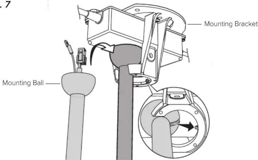
7. Hang fan
Raise fan to mounting bracket. Align rib in mounting bracket with slot in mounting ball, position mounting ball, and let fan hang freely (Fig. 7).
Gently twist downrod to ensure it is properly seated and will not move during fan operation.
Fig. 7
8a. Wire fan (no EMI filter)

Disconnect power to fan location before wiring fan.

Do not use the fan with a dimmer switch or a third-party switch.
Wire fan as shown using the wire connectors (Fig. 8a). Attach green and yellow ground wire to mounting bracket with the unpainted screw. Connect wiring harness from power supply to wiring harness from downrod, making sure that the wiring and safety cable are routed in the same direction.
Carefully tuck wiring into outlet box or building structure. Ensure wire connectors are turned upward and that wires are spread apart with grounded conductors on one side of the outlet box/mounting structure and ungrounded conductors on the other side.
Fig. 8a
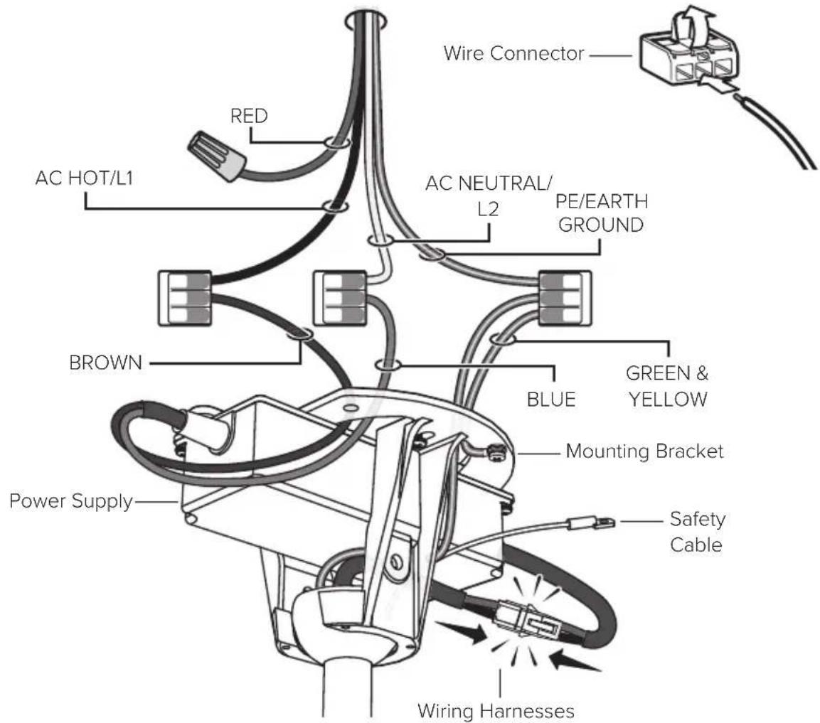
Supply Power Wire Color Chart
| North America 100–120 V Australia All other regions | ||
| AC Hot/L1 Brown | Black Brown or Red Brown | |
| AC Neutral/L2 Blue | White Black or Light Blue Blue | |
| PE/Earth Ground Green with Yellow | Green or Bare Copper Green with Yellow Green with Yellow | |
8b. Wire fan (with EMI filter)

Disconnect power to fan location before wiring fan.

Do not use the fan with a dimmer switch or a third-party switch.
Wire fan as shown using the wire connectors (Fig. 8b). Attach green and yellow ground wire to mounting bracket with the unpainted screw. Connect wiring harness from power supply to wiring harness from downrod, making sure that the wiring and safety cable are routed in the same direction.
Carefully tuck wiring into outlet box or building structure. Ensure wire connectors are turned upward and that wires are spread apart with grounded conductors on one side of the outlet box/mounting structure and ungrounded conductors on the other side.
Fig. 8b
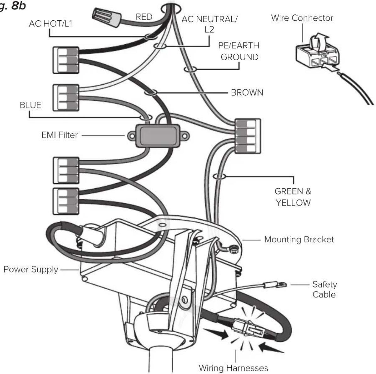
Supply Power Wire Color Chart
| North America 100–120 V Australia All other regions | ||
| AC Hot/L1 Brown | Black Brown or Red Brown | |
| AC Neutral/L2 Blue | White Black or Light Blue Blue | |
| PE/Earth Ground Green with Yellow | Green or Bare Copper Green with Yellow Green with Yellow | |
9. Install fan stabilizer (optional, outdoor fans only)
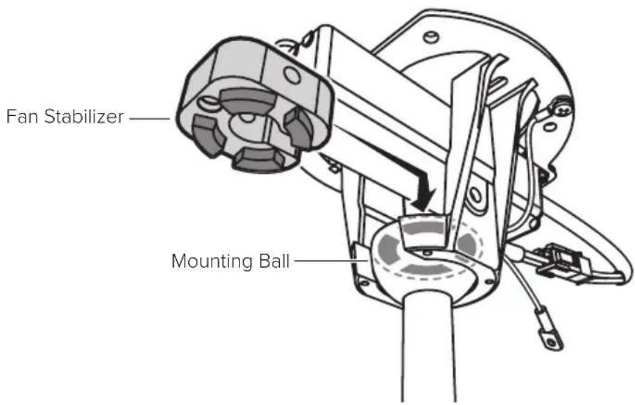
The fan stabilizer is included only if purchased as an outdoor fan accessory. Install stabilizer in covered outdoor locations on flat ceilings only.
If you purchased the fan stabilizer kit, fit stabilizer into notches on top of mounting ball (Fig. 9.1).
Fig. 9.1
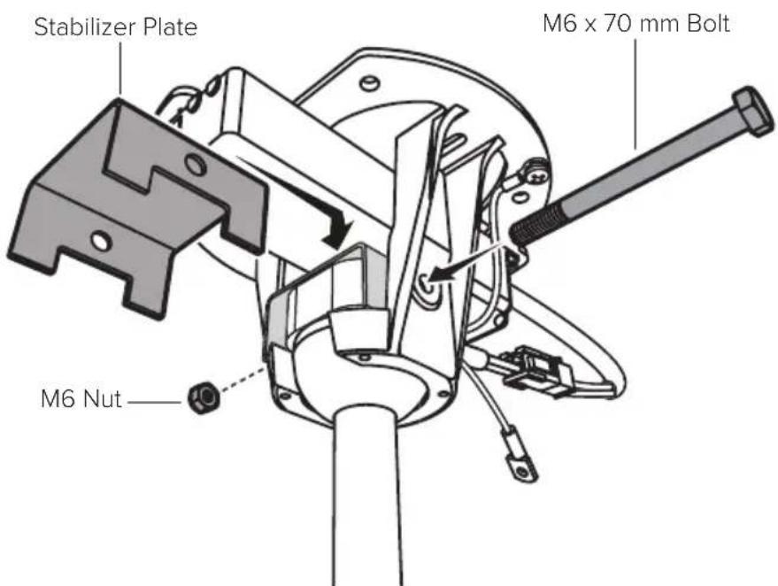
Secure stabilizer plate to stabilizer with the M6 x 70 mm bolt and M6 nut (Fig. 9.2).
Fig. 9.2
10. Secure safety cable
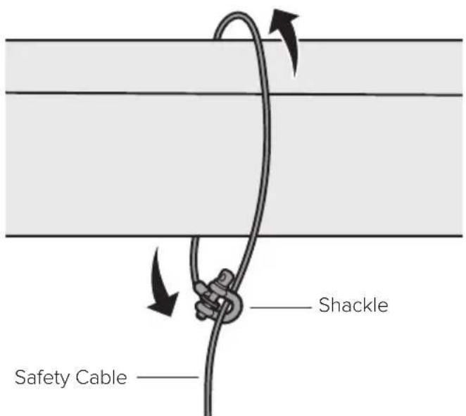
Some local safety codes require the safety cable to be secured directly to an existing part of the building structure (Canada, Singapore). It may be necessary to install additional structural material to provide attachment points. Check your local safety code if you are unsure.
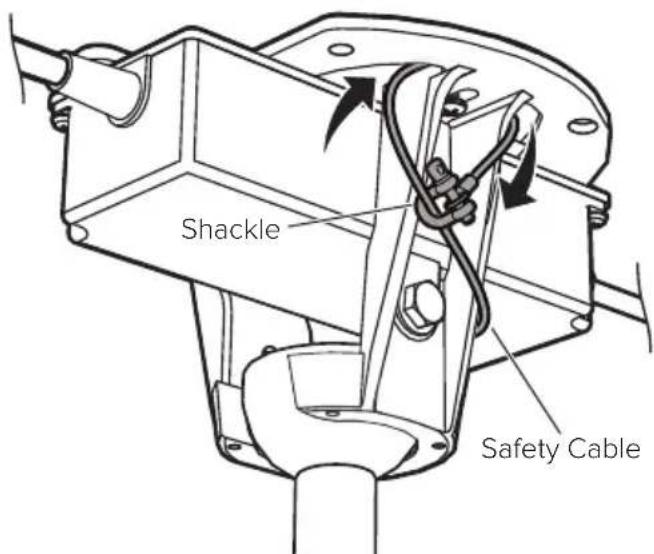
Mounting Bracket
Loop safety cable around mounting bracket, and then secure it with the shackle (Fig. 10.1).
Fig. 10.1
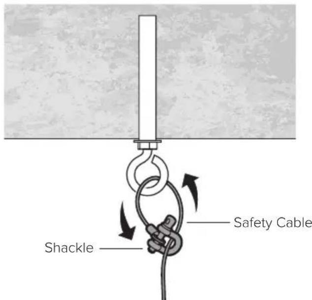
Anchor Hook
Loop safety cable around anchor hook, and then secure it with the shackle (Fig. 10.2).
Fig. 10.2
Building Structure
Loop safety cable around building structure, and then secure it with the shackle (Fig. 10.3). Acceptable building structures include a wooden beam or a metal mounting brace secured between two beams. In some cases it may be necessary to install additional structural material to provide attachment points.
Fig. 10.3
11. Raise canopy
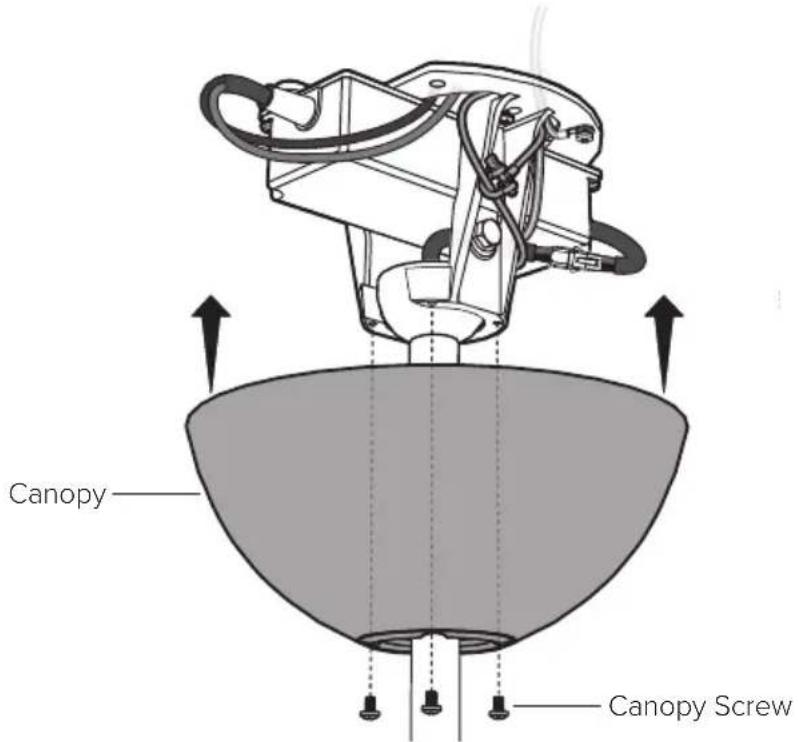
Raise canopy to mounting bracket, aligning the four holes on the canopy with the holes on the bracket. Secure canopy to mounting bracket with the painted screws (Fig. 11). Make sure all wires and the safety cable are tucked in the canopy.
Fig. 11
12. Install airfoils

If installing multiple fans, do not mix airfoils from different motor units. Each set of airfoils must be installed on the motor unit the airfoils shipped with.
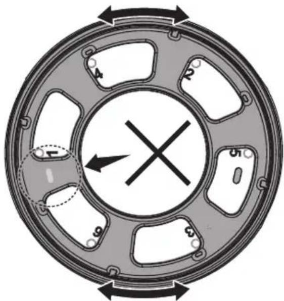
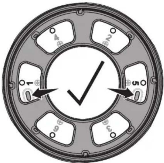
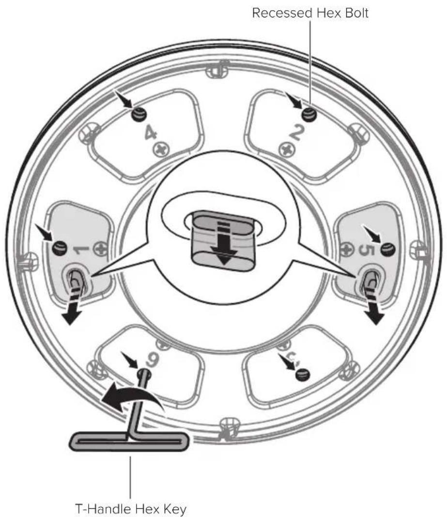
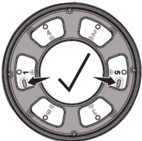
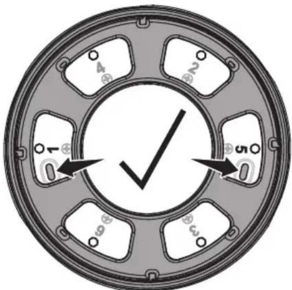
Before installing the airfoils, make sure the numbers 1 through 6 on the bottom of the fan are centered in the six openings, and make sure the two yellow tabs next to numbers 1 and 5 are visible (Fig. 12.1). You may need to push in the yellow tabs and rotate the fan hub until all six numbers are visible and centered.
Fig. 12.1
Incorrect Hub Alignment
Correct Hub Alignment
Before installing the airfoils, use the provided T-handle hex key to loosen the six recessed hex bolts above each number. Do NOT loosen the six Phillips head screws below each number. Loosen all six recessed hex bolts until both yellow tabs have descended as far as they will go (Fig. 12.2). The airfoils cannot be inserted into the motor unit until all six hex bolts are fully loosened and both yellow tabs are all the way down.
Fig. 12.2
Make sure both yellow tabs are all the way down.
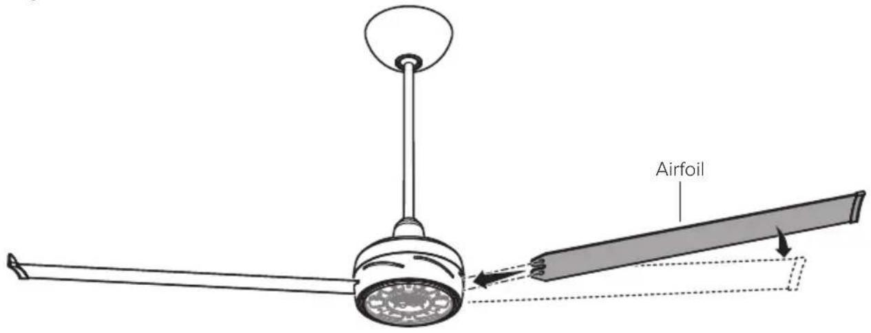
Slide the airfoils into the slots on the sides of the motor unit as shown (Fig. 12.3). Install each airfoil on the opposite side of the fan from the previous airfoil to prevent the fan from tilting. Make sure all airfoils are fully seated in the slots and that the numbered sticker on each airfoil matches the corresponding number on the bottom of the fan. Do NOT tighten the six recessed hex bolts until all airfoils are inserted.
Fig. 12.3
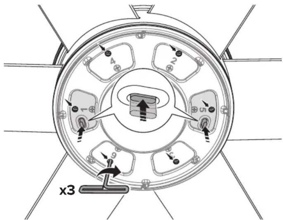
Use the provided T-handle hex key to tighten the six recessed hex bolts above each number on the bottom of the fan according to the numbered sequence. Do NOT tighten or loosen the six Phillips head screws below each number. Give each hex bolt three full turns with the hex key before moving to the next bolt in the sequence. Continue giving each hex bolt three turns in the numbered sequence until all six bolts are fully tightened and the yellow tabs next to numbers 1 and 5 are flush with the tab openings (Fig. 12.4).
Fig. 12.4
13. Install lower cover
Align slots on lower cover with tabs on bottom of fan. Twist lower cover clockwise until you hear and feel it click into place (Fig. 13.1).
Fig. 13.1
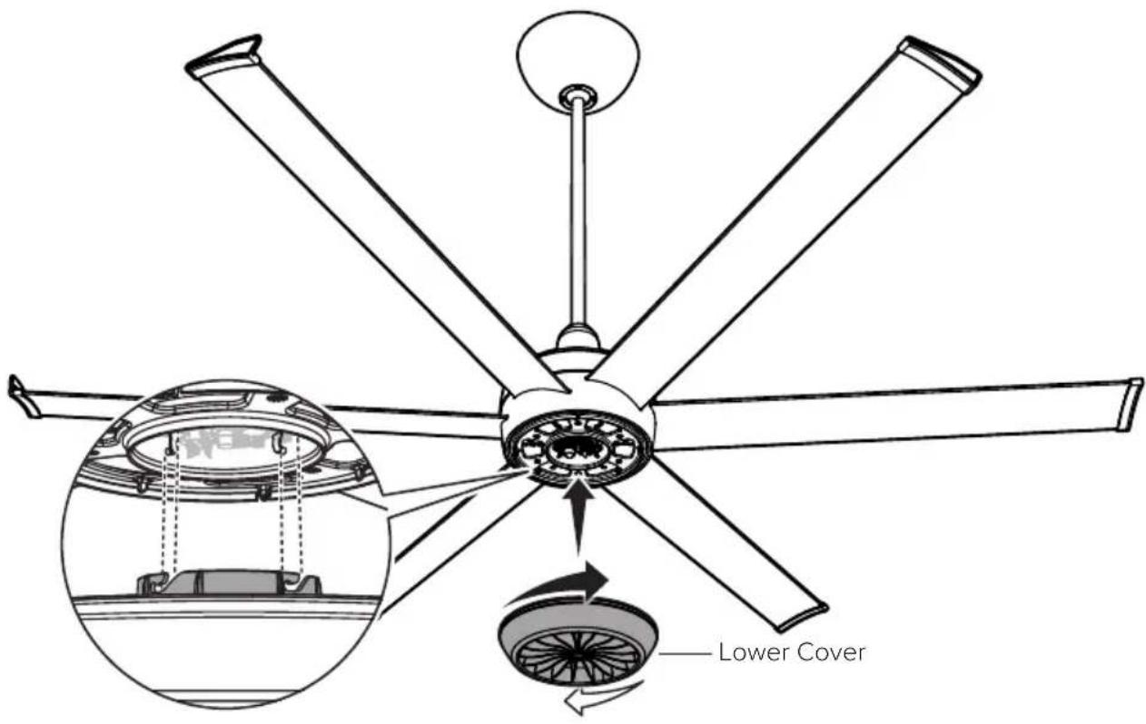
If you need to remove the lower cover, twist cover counterclockwise and slide down (Fig. 13.2).
Fig. 13.2
natural_image
Line drawing of a six-petal fan with rotation arrows indicating clockwise motion (no text or symbols)14. Test fan

CAUTION: Do not expose the remote control to rain or water.
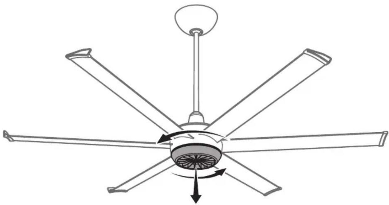
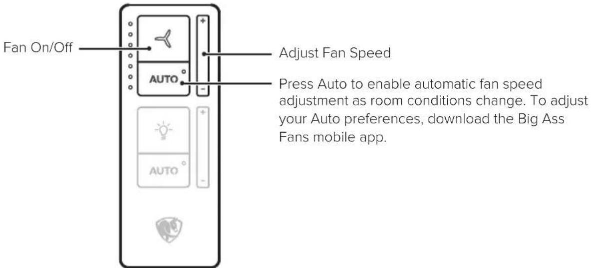
Congratulations! Installation is now complete. Turn on power, and then press any button on the remote control to pair it with your fan. Test your fan using the remote (Fig. 14). Note: It is normal for the fan to jerk forward and backward slightly for a few seconds when first turned on.
Fig. 14
Big Ass Fans Mobile App

Download the Big Ass Fans mobile app to group multiple fans, adjust their settings, and set your comfort preferences for hands-free control.
For smart device integration instructions, visit www.bigassfans.com/support
After connecting your fan to the app, use the app to make sure the fan's firmware is up to date.
Kick Ass™ Mode
Kick your fan into maximum overdrive with Kick Ass mode. Activate Kick Ass mode in the Big Ass Fans mobile app for an immediate airflow boost when you need it most.




TROUBLESHOOTING
| IssueSolution | |
| The fan jerks upon startup. | This is normal and may happen occasionally upon startup. An initial slight jerking forward and backward does not affect fan operation. |
| The fan will not start. | Make sure the fan is receiving power. Check your circuit breaker or fuse panel and wall switch for functionality.Make sure supply power is adequate.Make sure all wires are securely connected and the fan is properly wired and grounded.Make sure the plastic film in the remote's battery tray has been removed. |
| The fan wobbles. | Make sure all mounting hardware is secure and tight.Make sure all airfoils are aligned properly and are securely fastened to the motor unit.If an airfoil is damaged, contact Customer Service. Airfoils must be replaced as a set. Do not replace individual airfoils.Make sure the downrod and motor unit are hanging straight. Raise the wiring cover and locate the two bolts and nuts on the motor bracket. Loosen the hardware slightly to allow the fan to hang straight, and then re-tighten just past hand tight. Slide the wiring cover back in place.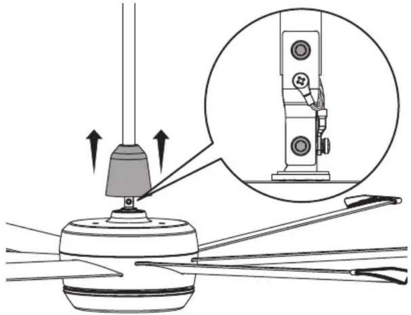 |
| The fan is noisy during operation. | Bring the fan to a complete stop.Gently turn the airfoils by hand, making sure there are no fan parts rubbing on the hub when the fan rotates.Check all mounting and fan hardware. If loose, tighten. |
| I need to reboot the fan. | Press and hold the remote On/Off button until the LED indicators start blinking. Within three seconds of the LEDs blinking, press the On/Off button again. When the LEDs stop blinking, the reboot is complete. |
| I need to pair my remote control with a different fan. | To pair a remote with a different fan, press ← and → until the LEDs blink. Make sure the remote is within range of the new fan, and then press any button to pair. |

WARNING: Risk of fire, electric shock, or injury to persons during cleaning and user maintenance. Disconnect the appliance from the power supply before servicing.
Please take a few moments each year to perform the following preventative maintenance procedures on your fan to ensure its safe and efficient operation.
Checking the safety cable
Check that the safety cable is properly installed by removing the canopy screws, sliding the canopy down the downrod, and examining the safety cable and hardware.
Checking the hardware
Make sure the mounting hardware and the screws securing the airfoils to the fan hub are securely fastened. Tighten the six airfoil screws on the bottom of the fan according to the numbered sequence. When finished, repeat the tightening sequence.
Checking the wiring
Make sure the wire connectors are secure and the ground wires are securely connected.
Cleaning the airfoils
Dust the airfoils regularly. If the fan becomes dirty, clean it with a soft cloth. Do not use solvents, gasoline, or any other chemical cleaners. These may cause surface distortion and damage to the fan.

For more operation, maintenance, and troubleshooting information, visit www.bigassfans.com/support
United States
2348 Innovation Drive
Lexington, KY 40511
USA
877-244-3267
Outside the U.S. (+1 859-233-1271)
bigassfans.com
Australia
35 French Street
Eagle Farm, Brisbane
QLD 4009
Australia
+61 1300 244 277
bigassfans.com/au
Manufacturer

2348 Innovation Drive
Lexington, KY 40511
USA
Manufacturing Site
2251 Innovation Drive
Lexington, KY 40511
USA
Warranty and WEEE Returns
2201 Jaggie Fox Way
Lexington, KY 40511
USA
Canada
2180 Winston Park Drive
Oakville, Ontario L6H 5W1
Canada
1844-924-4277
bigassfans.com/ca
Singapore
50 Ubi Crescent
01-01 Ubi TechPark
Singapore 408568
+65 6709 8500
bigassfans.com/sg
All Other Geographies
+1 859-410-6286
bigassfans.com
The information contained in this document is subject to change without notice. For the most up-to-date information, see the online printable installation guide at www.bigassfans.com/support
Google Play is a trademark of Google LLC.
www.bigassfans.com/patents · www.bigassfans.com/product-warranties
© 2024 DELTA T LLC. ALL RIGHTS RESERVED.
FRANÇAIS
CONTENU
natural_image
Three types of wrench and key tools: standard, simple, and T-shaped (no text or symbols)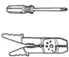
natural_image
Two types of electrical pliers shown in line drawings: a standard screwdriver and a wire clamp (no text or labels)
natural_image
Line drawing of a ladder with six legs, no text or symbols present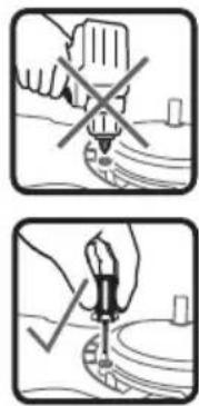
natural_image
Two-step diagram showing a hand using a tool to mark a crosshair on a surface, with no text or symbols present.natural_image
Technical diagram of a mechanical device with two vertical supports and directional arrows indicating motion or assembly (no text or symbols present)Moyeu mal aligné
natural_image
Line drawing of a six-petal fan with rotation arrows indicating clockwise motion (no text or symbols)2348 Innovation Drive
Lexington, KY 40511
États-Unis
877-244-3267
Eagle Farm, Brisbane
QLD 4009
Australie
+61 1300 244 277
bigassfans.com/au
Fabricant

2348 Innovation Drive
Lexington, KY 40511
États-Unis
Site de fabrication
2251 Innovation Drive
Lexington, KY 40511
États-Unis
Oakville, Ontario L6H 5W1
Canada
1844-924-4277
bigassfans.com/ca
Singapour
50 Ubi Crescent
01-01 Ubi TechPark
Singapour 408568
+65 6709 8500
bigassfans.com/sg
www.bigassfans.com/patents · www.bigassfans.com/product-warranties
© 2024 DELTA T LLC. TOUS DROITS RÉSERVÉS.
ESPAÑOL
CONTENIDO

natural_image
Three types of wrench and T-shaped tool outlines (no text or symbols)natural_image
Two types of electrical crimping tools shown in line drawings (no text or labels)
natural_image
Line drawing of a ladder on an inclined stand (no text or symbols)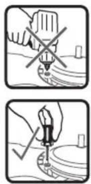
natural_image
Two-step diagram showing hand tool application: first with no cross, second with checkmark (no text or symbols)natural_image
Technical diagram of a mechanical device with two vertical supports and directional arrows indicating motion or assembly (no text or symbols present)Cubo mal alineado
natural_image
Line drawing of a six-petal fan with rotation arrows indicating clockwise motion (no text or symbols)2348 Innovation Drive
Lexington, KY 40511
Estados Unidos
877-244-3267
Eagle Farm, Brisbane
QLD 4009
Australia
+61 1300 244 277
bigassfans.com/au
Fabricante

2348 Innovation Drive
Lexington, KY 40511
Estados Unidos
2251 Innovation Drive
Lexington, KY 40511
Estados Unidos
Oakville, Ontario L6H 5W1
Canadá
1844-924-4277
bigassfans.com/ca
Singapur
50 Ubi Crescent
01-01 Ubi TechPark
Singapur 408568
+65 6709 8500
bigassfans.com/sg
www.bigassfans.com/patents · www.bigassfans.com/product-warranties
© 2024 DELTA T LLC. TODOS LOS DERECHOS RESERVADOS.

BIG ASS FANS®
bigassfans.com
- BIG ASS FANS® TURBO6
- Installation Guide
- √ Turn off Power at Breaker
- ☑ Gather Tools
- √ Prepare Fan Site and Gather Hardware
- ☑ Prepare Concrete Ceiling (if applicable)
- Install downrod
- Install lower safety cable and ground wire
- Reduce slack
- Position wiring cover and canopy
- Install mounting ball
- Install mounting bracket
- Hang fan
- 8a. Wire fan (no EMI filter)
- 8b. Wire fan (with EMI filter)
- Install fan stabilizer (optional, outdoor fans only)
- Secure safety cable
- Mounting Bracket
- Anchor Hook
- Building Structure
- Raise canopy
- Install airfoils
- Install lower cover
- Test fan
- CAUTION: Do not expose the remote control to rain or water.
- Big Ass Fans Mobile App
- Kick Ass™ Mode
- Checking the safety cable
- Checking the hardware
- Checking the wiring
- Cleaning the airfoils
- United States
- Australia
- Manufacturer
- Manufacturing Site
- Warranty and WEEE Returns
- Canada
- Singapore
- 01-01 Ubi TechPark
- All Other Geographies
- FRANÇAIS
- CONTENU
- Fabricant
- Site de fabrication
- Singapour
- ESPAÑOL
- CONTENIDO
- Fabricante
- Singapur
- BIG ASS FANS®
Brand : Big Ass Fans
Model : Turbo6
Category : Fan