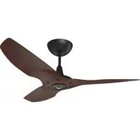
Haiku Indoor - Fan Big Ass Fans - Free user manual and instructions
Find the device manual for free Haiku Indoor Big Ass Fans in PDF.


| Product Type | Ceiling fan with integrated LED lighting |
| Brand | Big Ass Fans |
| Model | Haiku Indoor |
| Blade Diameter | 1.3 m (52 in) / 1.5 m (60 in) / 2.1 m (84 in) |
| Input Voltage | 100-120 V (North America) / 220-240 V (other regions) |
| Motor | High-efficiency DC motor (silent) |
| Remote Control Functions | On/Off, timer (1 to 8 h), lighting, variable speed, natural breeze mode, night mode |
| Lighting | Integrated LED, dimmable via remote |
| Mounting Types | Universal (for sloped ceilings), Standard, Short |
| Recommended Ceiling Height | 2.4 m to 5.5 m (8 ft to 18 ft) |
| Included Accessories | Remote control, 508 mm and 813 mm extension rods, mounting kit |
| Maintenance | Dust regularly; clean blades with a soft, dry cloth |
| Safety | Do not use a dimmer; cut power before any intervention; safety cable included |
| Spare Parts Available | Extension rods (508 mm, 813 mm, 1,219 mm, 1,524 mm), stabilization kit for sloped ceiling |
| Repairability | Pivot screw for tilt adjustment; reset possible via remote |
Frequently Asked Questions - Haiku Indoor Big Ass Fans
User questions about Haiku Indoor Big Ass Fans
0 question about this device. Answer the ones you know or ask your own.
Ask a new question about this device
Download the instructions for your Fan in PDF format for free! Find your manual Haiku Indoor - Big Ass Fans and take your electronic device back in hand. On this page are published all the documents necessary for the use of your device. Haiku Indoor by Big Ass Fans.
USER MANUAL Haiku Indoor Big Ass Fans
natural_image
White line icon of a screwdriver inside a circle (no text or symbols)
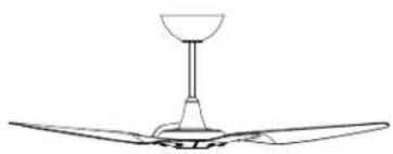
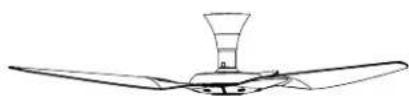
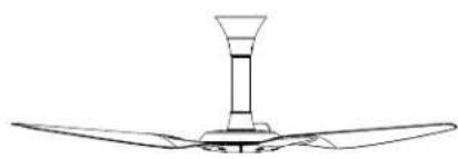
Follow the instructions for your mount type. Each mount uses different parts and hardware.
Universal Mount
Mounting
Sloped or flat ceilings from 11 to 18 feet (3.4 to 5.5 meters)
Input Voltage
100–240 VAC, 50–60 Hz
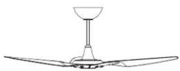
natural_image
Line drawing of a three-bladed propeller with a conical top (no text or symbols)Low Profile Mount
Mounting
Flat ceilings as low as 8 feet (2.4 meters)
Input Voltage
100–240 VAC, 50–60 Hz
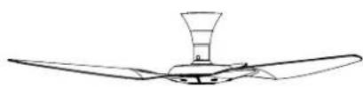
natural_image
Line drawing of a three-bladed air conditioner fan with a conical top (no text or symbols)Standard Mount
Mounting
Flat ceilings from 8.5 to 11 feet (2.5 to 3.4 meters)
Input Voltage
100–240 VAC, 50–60 Hz
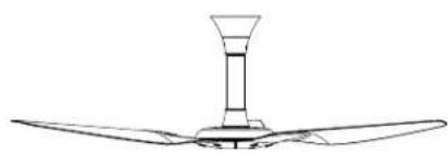
natural_image
Line drawing of a three-bladed air duct system with a conical top (no text or symbols)READ AND SAVE THESE INSTRUCTIONS
BEFORE YOU START
Turn Off Power
Contact a licensed electrician if you are uncomfortable performing electrical work. A licensed electrician must install the fan if required by local code.

Do not use the fan with a dimmer switch.

Turn off power at breaker!
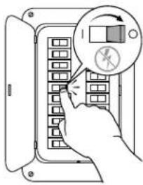
√ Prepare Fan Site
Outlet Box: Make sure your outlet box is suitable for fan support. If there is not an outlet box at the fan location, install one on a ceiling joist or beam.
Concrete Ceiling: Install an anchor hook for the safety cable if required by your local building and safety code. See the following page for installation details.
Wood Ceiling Joist: Attach the mounting plate or mounting bracket directly to the joist using two wood screws (not supplied). Big Ass Fans recommends using corrosion-resistant 12-11 x 45 mm hex head timber screws with seal.
☑ Gather Tools
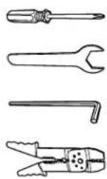
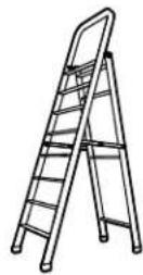
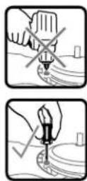
☑ Select Extension Tube (Universal Mount Only)
If your fan uses the universal mount, you will need to select the appropriate extension tube for your ceiling height and slope.
See page 4 for a guide to select the most appropriate extension tube.
Concrete Ceiling
Install an anchor hook for the safety cable if required by your local building and safety code.
Standard Mount Universal MountLow Profile Mount

Low Profile Mount
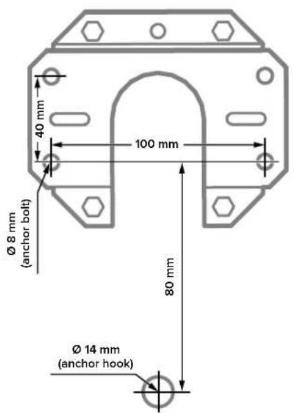
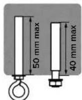
Drill four ∅ 8 mm holes in the pattern shown. The hole depth should not exceed 40 mm. Remove any dust from the holes. Insert four anchor bolts into the holes. Strike the heads of the anchor bolts with a hammer, ensuring the bolt sleeves are flush with the ceiling surface. Position the mounting plate on the anchor bolts. Ensure all four anchor bolts are fully tightened to expand and lock the anchors.
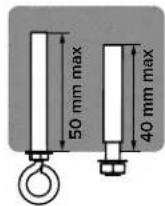
If required by local building and safety codes, install an anchor hook for the safety cable. Drill a 14 mm hole for the anchor hook in the pattern shown. The hole depth should not exceed 50 mm. Remove any dust from the hole, and then insert the anchor hook and fully tighten.
Standard Mount
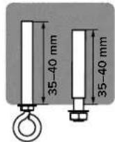
Drill three ∅ 12–12.5 mm holes in the pattern shown. The hole depth should not exceed 35–40 mm. Remove any dust from the holes. Insert three anchor bolts into the holes. Strike the heads of the anchor bolts with a hammer, ensuring the bolt sleeves are flush with the ceiling surface. Position the hanger plate on the anchor bolts. Ensure all three anchor bolts are fully tightened to expand and lock the anchors.
If required by local building and safety codes, install an anchor hook for the safety cable. Drill a ∅ 8–8.5 mm hole for the anchor hook adjacent to the hanger plate. The hole depth should not exceed 35–40 mm. Remove any dust from the hole, and then insert the anchor hook and fully tighten.
Universal Mount
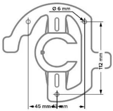
Drill three ∅ 6 mm holes in the pattern shown. The hole depth should not exceed 40 mm. Remove any dust from the holes. Insert three anchor bolts into the holes. Strike the heads of the anchor bolts with a hammer, ensuring the bolt sleeves are flush with the ceiling surface. Position the mounting bracket on the anchor bolts. Ensure all three anchor bolts are fully tightened to expand and lock the anchors.
If required by local building and safety codes, install an anchor hook for the safety cable. Drill a ∅ 8 mm hole for the anchor hook. The hole depth should not exceed 50 mm. Remove any dust from the hole, and then insert the anchor hook and fully tighten.
Choosing an Extension Tube (Universal Mount Only)
Consult the tables below to select the appropriate extension tube for your fan.
Ceiling Height
For optimum performance, Big Ass Fans recommends the following extension tube lengths based on ceiling height.
| Ceiling Height Extension Tube Length | |
| 9.5–11 ft(2.9–3.4 m) | 20 in.(508 mm) |
| 11–13 ft(3.4–4 m) | 32 in.(813 mm) |
| 13–14 ft *(4–4.3 m) * | 48 in.*(1219 mm) * |
| >14 ft *(>4.3 m) * | 60 in.*(1524 mm) * |
* Big Ass Fans recommends using an extended length extension tube for ceiling heights over 13 ft (4 m). The fan comes standard with 20 in. (508 mm) and 32 in. (813 mm) extension tubes. Other lengths are available by contacting Customer Service.
Ceiling Slope
Haiku fans with a universal mount can be installed on sloped ceilings with an angle no greater than 33°.
| Fan Diameter | Maximum Ceiling Slope | Extension Tube Length |
| 52 in. (1.3 m) | 26^ | 20 in. (508 mm) |
| 52 in. (1.3 m) | 33^ | 32 in. (813 mm) |
| 60 in. (1.5 m) | 22^ | 20 in. (508 mm) |
| 60 in. (1.5 m) | 33^ | 32 in. (813 mm) |
| 84 in. (2.1 m) | 16^ | 20 in. (508 mm) |
| 84 in. (2.1 m) | 29^ | 32 in. (813 mm) |

If installing your fan outdoors on a sloped ceiling, Big Ass Fans recommends installing the Sloped Ceiling Fan Stabilizer kit (available separately).
Haiku Remote
Do not expose the remote control to rain or water.

Turns fan on or off.

Sets fan timer length of up to eight hours. Each press extends timer by one hour.

Turns light on or off. Clears active fan timer.


Increases fan speed/light brightness. Varies fan speed to simulate a natural breeze.

Decreases fan speed/light brightness.

Automatically adjusts your fan speed overnight to keep you comfortable while you sleep.
UNIVERSAL MOUNT
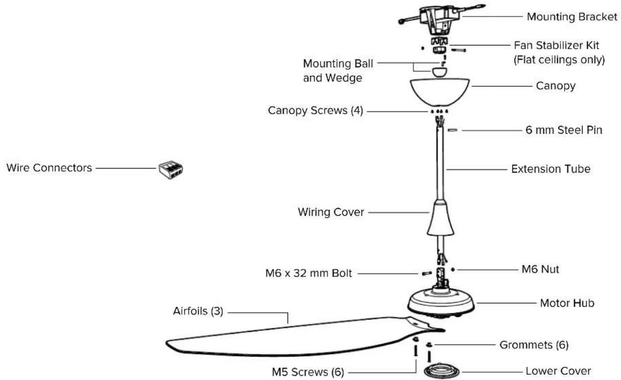
Safety cable not shown
If the EMI filter is included, install it with your fan.
For sloped ceilings, Big Ass Fans recommends installing the Sloped Ceiling Fan Stabilizer Kit (available separately).
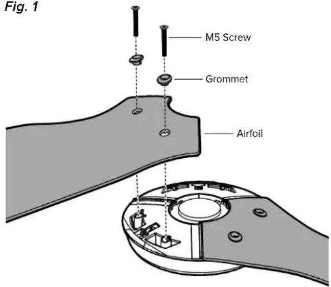
1 Install Airfoils
Moving clockwise, align each airfoil on the fan hub and secure it with the airfoil hardware (Fig. 1). Make sure the sticker color on each airfoil matches the corresponding sticker color on the fan hub!
Fig. 1
HAIKU BY BIG ASS FANS
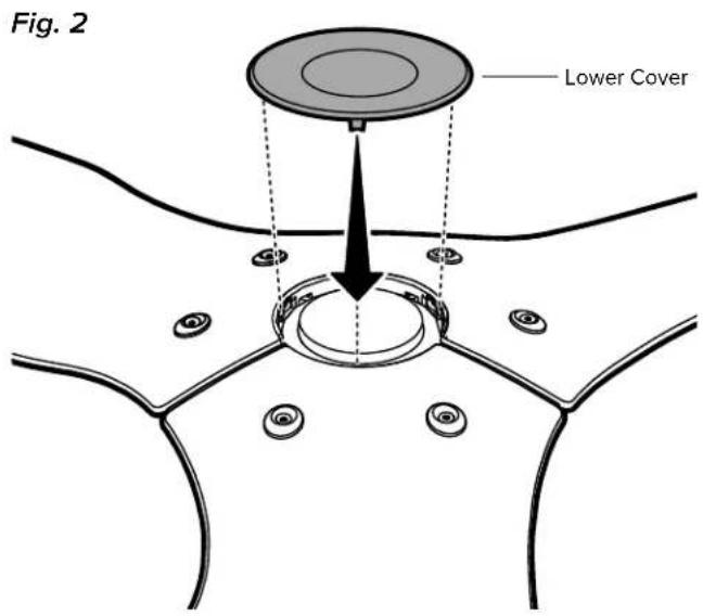
2 Install Lower Cover
Attach the lower cover as shown (Fig. 2).
3 Attach Extension Tube and Wiring Harness
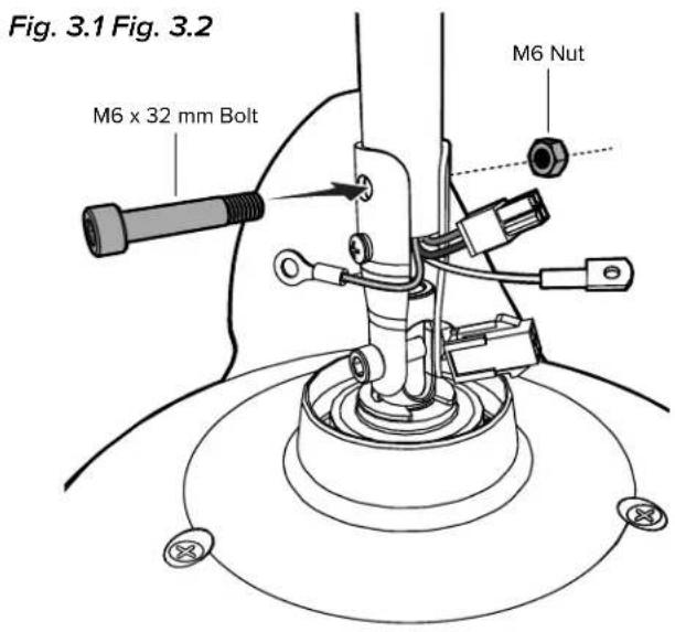
Align the holes on the extension tube with the holes on the motor bracket, and then secure the tube with the M6 x 32 mm bolt and M6 nut (Fig. 3.1).
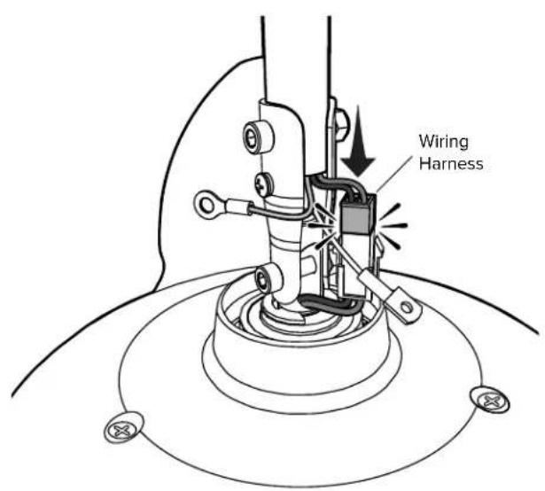
Connect the wiring harness from the extension tube to the receptacle from the motor hub (Fig. 3.2).
REV. D. J ©2018 BIG ASS FANS ALL RIGHTS RESERVED
4 Install Lower Safety Cable and Ground Wire
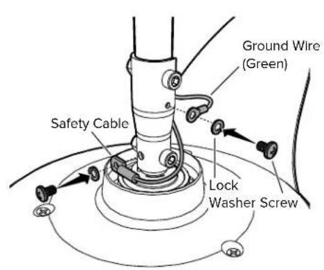
Install the safety cable and ground wire lugs with the unpainted screws and lock washers (Fig. 4.1).
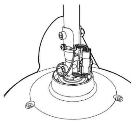
Make sure all hardware is secure, and then gently tug the cables at the top of the extension tube to reduce slack (Fig. 4.2).
Slide the wiring cover down the extension tube, resting it on the fan hub. Make sure no wires are visible between the cover and fan hub. Slide the canopy down the extension tube (Fig. 4.3).
Fig. 4.1 Fig. 4.2 Fig. 4.3
natural_image
Technical line drawing of a mechanical assembly with no visible text or symbols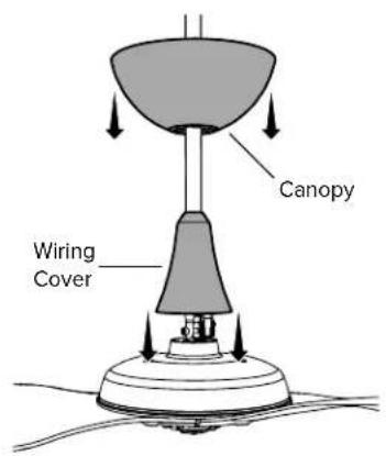
HAIKU BY BIG ASS FANS
5 Install Mounting Ball
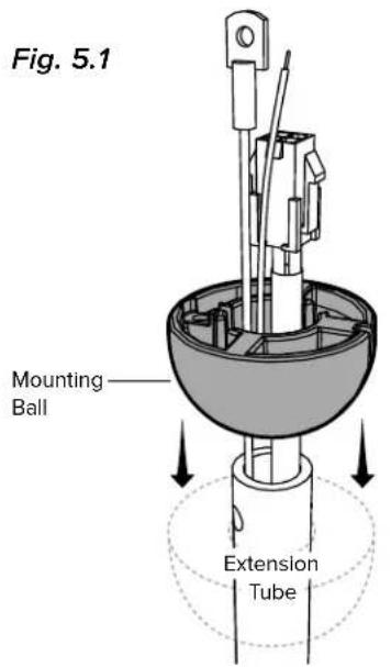
Slide the mounting ball over the extension tube (Fig. 5.1).
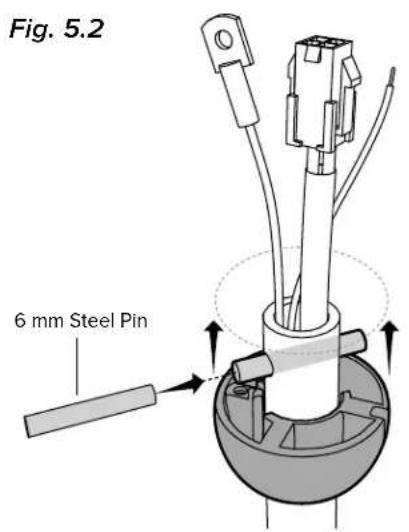
Insert the 6 mm steel pin into the hole at the top of the extension tube, and then slide the mounting ball upward, seating the steel pin in the inner slots (Fig. 5.2).
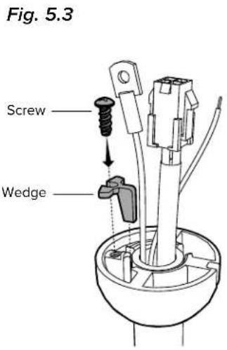
Insert the wedge into the mounting ball and secure it with the screw. Tighten the screw enough to prevent movement between the mounting ball and extension tube, but do not over-tighten (Fig. 5.3).
REV. D. J ©2018 BIG ASS FANS ALL RIGHTS RESERVED
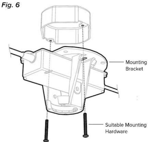
6 Install Mounting Bracket
⚠️ Disconnect power to the fan location before installing the mounting bracket!
Secure the mounting bracket to the mounting structure with suitable hardware (Fig. 6).
Outlet box shown. Your mounting structure may differ from the illustration.
HAIKU BY BIG ASS FANS
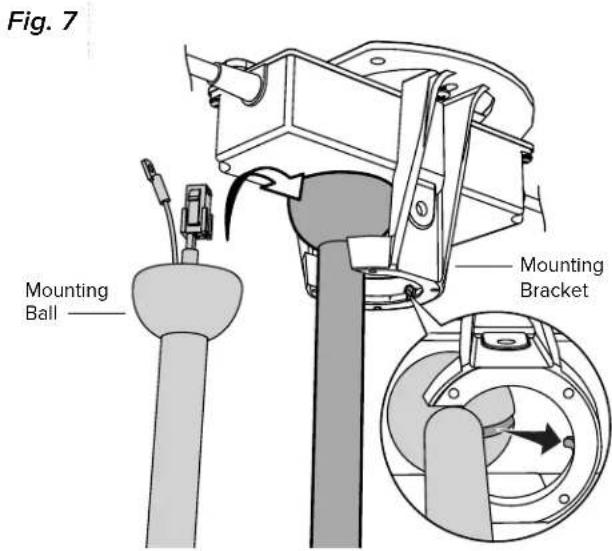
7 Hang Fan
Raise the fan to the mounting bracket. Align the rib in the mounting bracket with the slot in the mounting ball, position the mounting ball, and let the fan hang freely (Fig. 7).
Gently twist the extension tube to ensure it is properly seated and will not move during fan operation.
8 Wire the Fan
Disconnect power to the fan location before wiring the fan!
Do not connect the fan to a damaged power source! Do not attempt to resolve electrical failures on your own. Consult a qualified electrician if uncertain of the electrical installation of this fan.
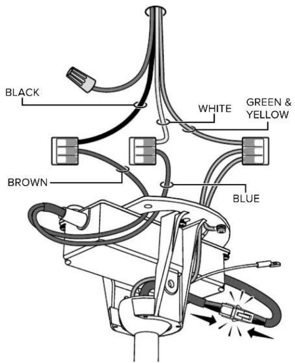
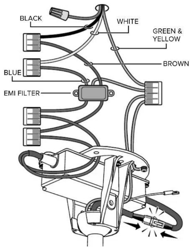
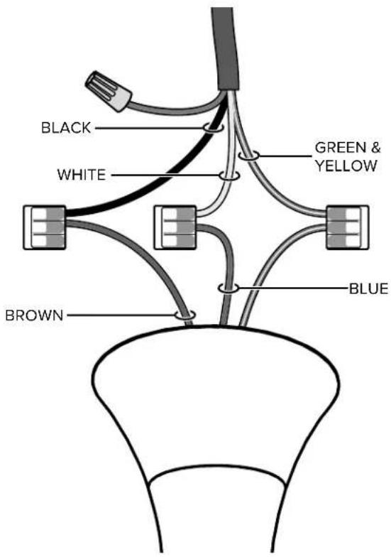
Wire the fan as shown in the diagram using the wire connectors (Fig. 8). If your fan packaging included an EMI filter, install it as shown.
Attach the green ground wire to the mount with the unpainted screw. Connect the wiring harness from the power supply to the wiring harness from the extension tube, making sure that the wiring and safety cable are routed in the same direction.
Fig. 8

natural_image
Simple line drawing of a connector with an attached cable and directional arrows (no text or symbols)| North America100–120 V | All other regions | |
| AC Hot/L1 Brown | Black Brown | |
| AC Neutral/L2 Blue | White Blue | |
| PE/Earth Ground Green with Yellow | Green or Bare Copper | Green with Yellow |
Wiring Diagram (No EMI Filter)
Wiring Diagram (With EMI Filter)
HAIKU BY BIG ASS FANS
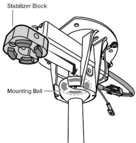
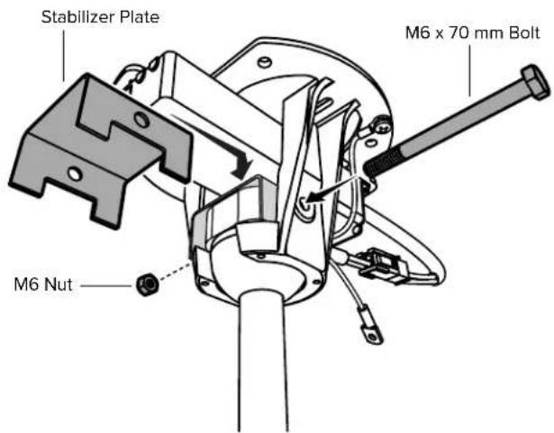
9 Install Flat Ceiling Fan Stabilizer

If installing your fan on a sloped ceiling, Big Ass Fans recommends installing the Sloped Ceiling Fan Stabilizer kit.
Fit the stabilizer block into the notches on top of the mounting ball (Fig. 9.1).
Secure the stabilizer plate to the stabilizer block with the M6 x 70 mm bolt and M6 nut (Fig. 9.2).
Fig. 9.1 Fig. 9.2
10 Secure Safety Cable
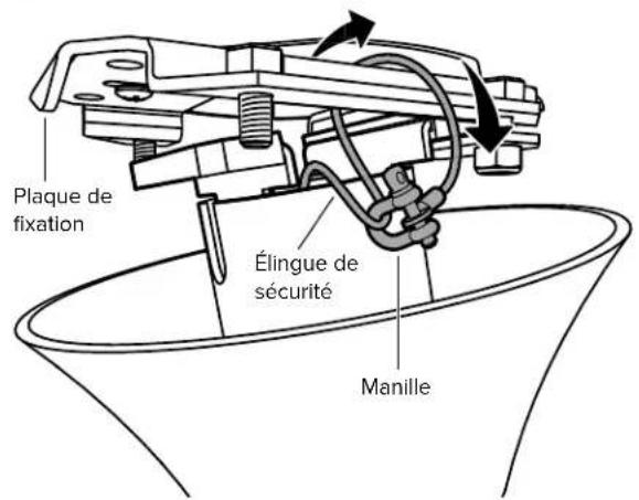
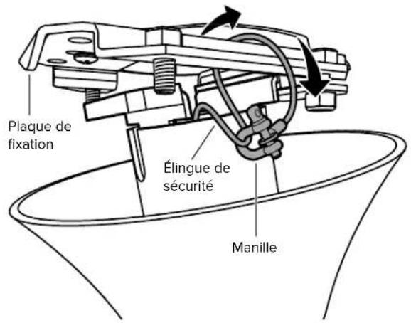
Loop the safety cable around the mounting bracket or building structure, and then secure it with the shackle (Fig. 10).
Fig. 10
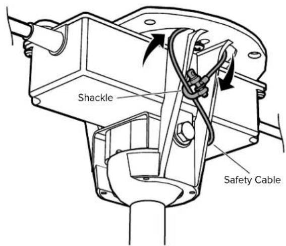

Canada: The safety cable must be secured directly to an existing part of the building structure. It may be necessary to install additional structural material to provide attachment points.
HAIKU BY BIG ASS FANS
11 Raise Canopy
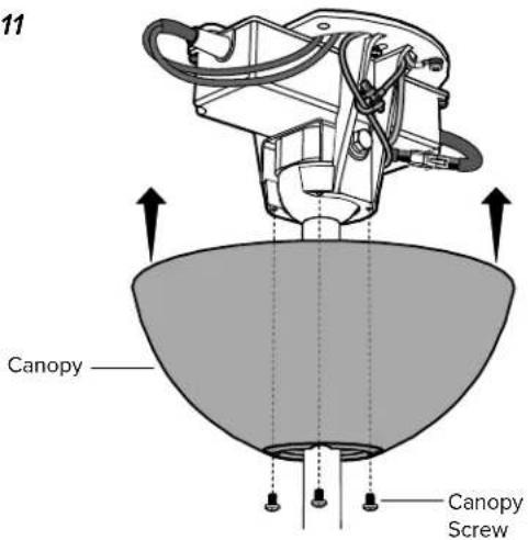
Raise the canopy to the mounting bracket, aligning the four holes on the canopy with the holes on the bracket. Secure the canopy to the mounting bracket with the painted screws (Fig. 11). Make sure all wires and the safety cable are tucked in the canopy.
Fig. 11
Congratulations!
Installation is now complete. Test your fan using the remote control.
LOW PROFILE MOUNT
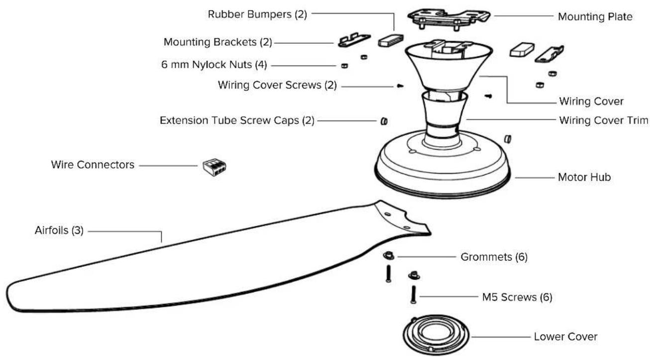
Use the extension tube screw caps that match the color of your fan. Safety cable not shown.
1 Install Mounting Plate and Single Bracket
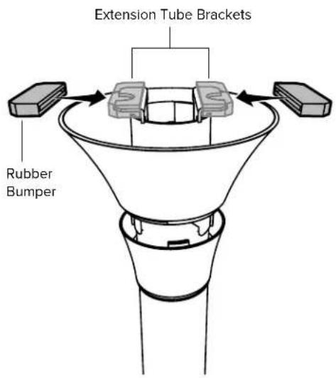
Slide the rubber bumpers onto the extension tube brackets (Fig. 1.1).
Secure the mounting bracket to the mounting structure with suitable hardware (Fig. 1.2). Your mounting structure may differ from the illustration.
Loosely attach one mounting bracket to the mounting plate with two 6 mm nylock nuts, but do not fully tighten (Fig. 1.3).
Fig. 1.1 Fig. 1.2 Fig. 1.3
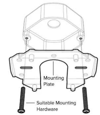
Outlet box shown. Your mounting structure may differ from the illustration.

HAIKU™ BY BIG ASS FANS
2 Secure Safety Cable
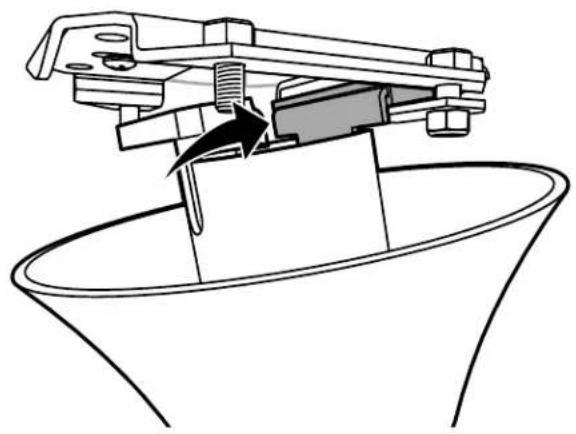
Raise the fan to the bracket and temporarily rest one rubber bumper in the space between the bracket and plate (Fig. 2.1). While supporting the fan, loop the safety cable around the mounting plate or building structure, and then secure it with the shackle (Fig. 2.2).
Fig. 2.1
natural_image
Technical line drawing of a mechanical assembly with no visible text or symbolsFig. 2.2
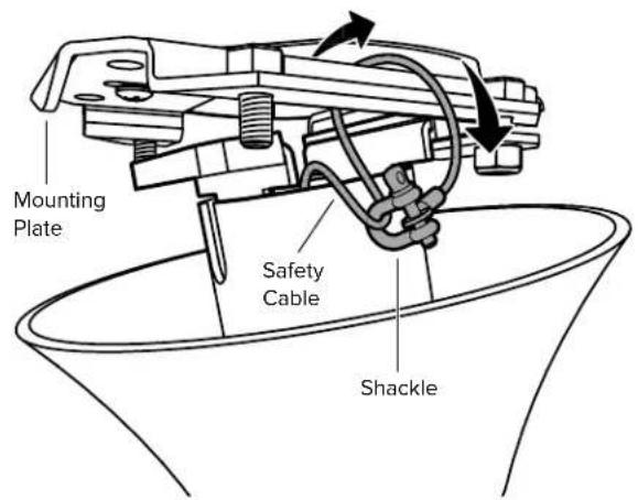

Canada: The safety cable must be secured directly to an existing part of the building structure. It may be necessary to install additional structural material to provide attachment points.
3 Wire Fan
⚠️ Disconnect power to the fan location before wiring the fan!
Do not connect the fan to a damaged power source! Do not attempt to resolve electrical failures on your own. Consult a qualified electrician if uncertain of the electrical installation of this fan.
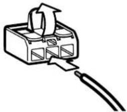
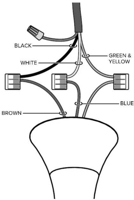
Allow the fan to hang from the safety cable. Wire the fan as shown in the diagram using the wire connectors (Fig. 3).
Fig. 3
natural_image
Simple line drawing of a connector with an arrow indicating upward motion (no text or symbols)| North America100–120 V | All other regions | |
| AC Hot/L1 Brown | Black Brown | |
| AC Neutral/L2 Blue | White Blue | |
| PE/Earth Ground Green with Yellow | Green or Bare Copper | Green with Yellow |
HAIKU BY BIG ASS FANS
Wiring Diagram
4 Install Mounting Brackets
Raise the fan to the mount. Insert one rubber bumper between the mounting plate and the loosely installed mounting bracket with the 6 mm nylock nuts.
Secure the other bumper with the remaining mounting bracket and nuts (Fig. 4).
Tighten all hardware.
Fig. 4

5 Install Wiring Cover
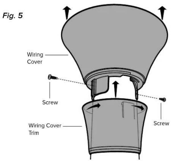
Raise the wiring cover, allowing about a 1/8" (3 mm) gap at the ceiling. Align the mounting slots with the screw holes on the extension tube, and secure it with the wiring cover screws.
Slide the trim up the extension tube, aligning the tabs on the inside with the slots on the bottom of the wiring cover. Twist clockwise to snap the trim into position (Fig. 5).
REV. D. J ©2018 BIG ASS FANS ALL RIGHTS RESERVED
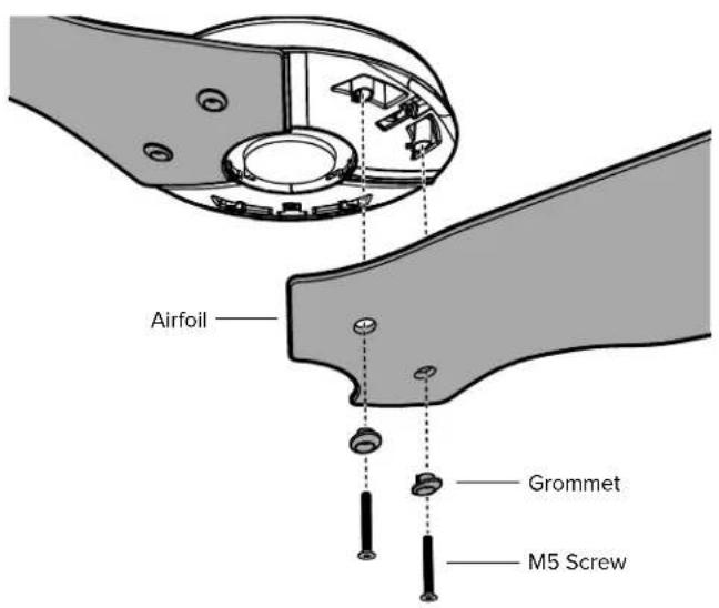
6 Install Airfoils
Moving clockwise, align each airfoil on the fan hub and secure it with the airfoil hardware (Fig. 6). Make sure the sticker color on each airfoil matches the corresponding sticker color on the fan hub!
Fig. 6
HAIKU BY BIG ASS FANS
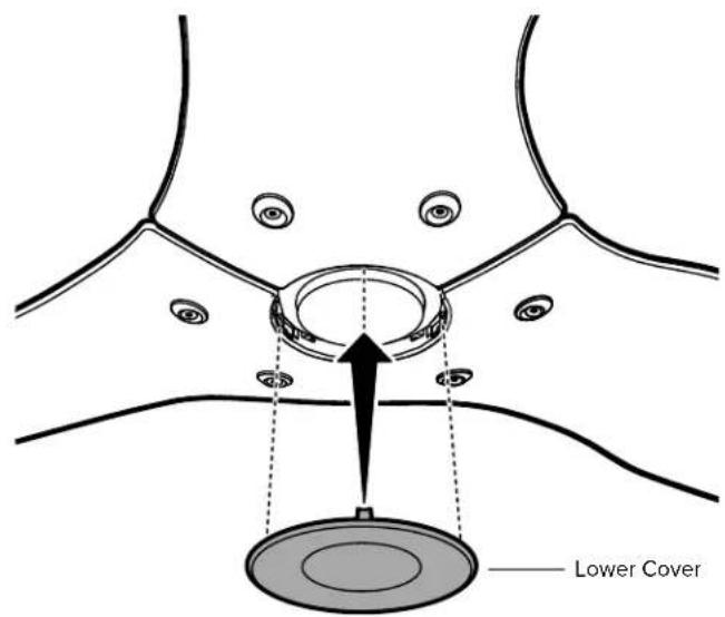
7 Install Lower Cover
Attach the lower cover as shown (Fig. 7).
Fig. 7
Congratulations!
Installation is now complete. Test your fan using the remote control.
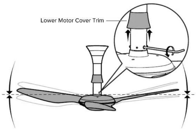
If your fan appears slightly tilted, raise the lower motor cover trim and locate the pivot bolt. Loosen the bolt with a 5 mm hex key to allow the fan to hang straight, and then re-tighten.

STANDARD MOUNT
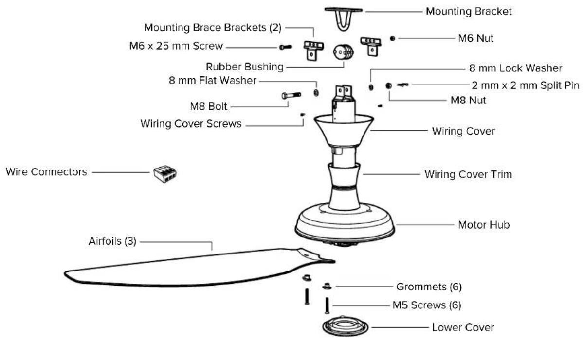
Use the extension tube screw caps that match the color of your fan. Safety cable not shown.
HAIKU BY BIG ASS FANS
1 Install Mounting Bracket
Seat the rubber bushing in the mounting bracket (Fig. 1).
Secure the mounting bracket to the mounting structure with suitable hardware (Fig. 1). Your mounting structure may differ from the illustration.
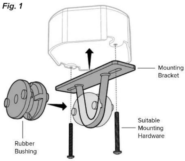
Outlet box shown. Your mounting structure may differ from the illustration.
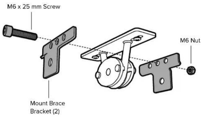
2 Secure Mount Brace Brackets
Loosely install the mount brace brackets with the provided hardware (Fig. 2). The bolt should be inserted in the middle hole. Do not fully tighten the hardware.
Fig. 2
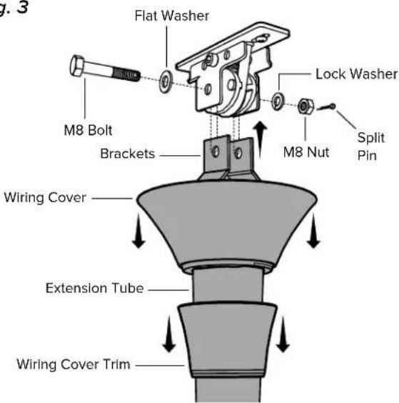
3 Hang Fan
Raise the extension tube to the mount, and insert the extension tube brackets between the mount brackets and the rubber bushing so that the mounting holes are aligned. Secure the extension tube with the mounting hardware (Fig. 3).

Fully tighten all hardware until the brackets slightly compress the rubber bushing.
Fig. 3
HAIKU BY BIG ASS FANS
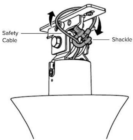
4 Secure Safety Cable
While supporting the fan, loop the safety cable around the mounting bracket or building structure, and then secure it with the shackle (Fig. 4).
Fig. 4

Canada: The safety cable must be secured directly to an existing part of the building structure. It may be necessary to install additional structural material to provide attachment points.
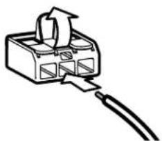
5 Wire Fan
Disconnect power to the fan location before wiring the fan!
Do not connect the fan to a damaged power source! Do not attempt to resolve electrical failures on your own. Consult a qualified electrician if uncertain of the electrical installation of this fan.
Wire the fan as shown in the diagram using the wire connectors (Fig. 5).
Fig. 5
natural_image
Simple line drawing of a connector with arrows indicating rotation and cable (no text or symbols)| North America100–120 V | All other regions | |
| AC Hot/L1Brown | Black Brown | |
| AC Neutral/L2Blue | White Blue | |
| PE/Earth GroundGreen with Yellow | Green or BareCopper | Green with Yellow |
Wiring Diagram
REV. D. J ©2018 BIG ASS FANS ALL RIGHTS RESERVED
6 Install Wiring Cover and Trim
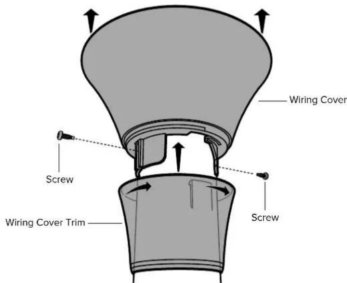
Raise the wiring cover, allowing about a 1/8" (3 mm) gap at the ceiling. Align the mounting slots with the screw holes on the extension tube, and secure it with the wiring cover screws.
Slide the trim up the extension tube, aligning the tabs on the inside with the slots on the bottom of the wiring cover. Twist clockwise to snap the trim into position (Fig. 6).
Fig. 6
HAIKU BY BIG ASS FANS
7 Install Airfoils
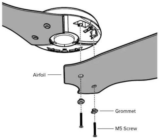
Moving clockwise, align each airfoil on the fan hub and secure it with the airfoil hardware (Fig. 7). Make sure the sticker color on each airfoil matches the corresponding sticker color on the fan hub!
Fig. 7
8 Install Lower Cover
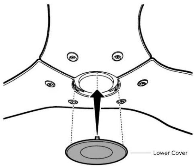
Attach the lower cover as shown (Fig. 8).
Fig. 8
Congratulations!
Installation is now complete. Test your fan using the remote control.
If your fan appears slightly tilted, raise the lower motor cover trim and locate the pivot bolt. Loosen the bolt with a 5 mm hex key to allow the fan to hang straight, and then re-tighten.
HAIKU™ BY BIG ASS FANS
TROUBLESHOOTING
Your fan may occasionally jerk forward and backward upon startup. This is normal and does not affect fan operation.
Try these troubleshooting steps before contacting Customer Service. For additional operation, maintenance, and troubleshooting information, visit bigassfans.com/support
| Issue Solution | |
| The fan will not start. | Make sure the fan is receiving power.Check your circuit breaker or fuse panel and wall switch for functionality.Make sure the fan is properly wired and grounded.Make sure the plastic film in the remote's battery tray has been removed. |
| The fan wobbles. | Remove the airfoils and make sure the colored dot sticker on each airfoil matches the corresponding sticker on the motor hub. If the stickers do not match, move the airfoils to the matching attachment points. |
| The fan appears slightly tilted.(Low profile and standard mounts only.) | Raise the lower motor cover trim and locate the pivot bolt. Loosen the bolt with a 5 mm hex key to allow the fan to hang straight, and then re-tighten. |
| The fan is noisy during operation. | Bring the fan to a complete stop.Gently turn the airfoils by hand, making sure there are no fan parts rubbing on the motor hub when the fan rotates.Check all mounting and fan hardware. If loose, tighten. |
| I need to reboot the fan. | Press and hold the On/Off button until the LED indicators start blinking.Within three seconds of the LEDs flashing, press the On/Off button again. When the LEDs stop blinking, the reboot is complete. |
FRANÇAIS
100–240 V CA, 50–60 Hz
natural_image
Line drawing of a double-decker air conditioner with a glass top and three blades (no text or symbols)Fixation courte
Installation
100–240 V CA, 50–60 Hz
natural_image
Line drawing of a three-bladed air duct with a conical top (no text or symbols)Fixation standard
Installation
100–240 V CA, 50–60 Hz
natural_image
Line drawing of a three-bladed fan or propeller with a central conical top (no text or symbols)natural_image
Technical line drawing of a mechanical assembly with no visible text or symbols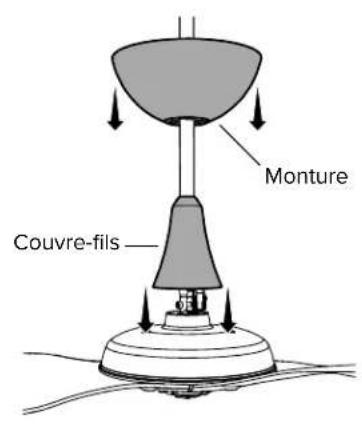
natural_image
Simple line drawing of a connector with a cable, no text or symbols presentnatural_image
Technical line drawing of a mechanical assembly with no visible text or symbolsFig. 2.2
natural_image
Simple line drawing of a connector with arrows indicating rotation and cable (no text or symbols)HAIKU® BY BIG ASS FANS
natural_image
Simple line drawing of a connector with a cable and arrow indicating rotation (no text or symbols)natural_image
Line drawing of a double-decker air conditioner with a conical top and fan base (no text or symbols)natural_image
Line drawing of a three-bladed air conditioner fan with a conical top (no text or symbols)Montura estándar
Montura
natural_image
Line drawing of a three-bladed air conditioner fan with a conical top (no text or symbols)natural_image
Line drawings of four different types of wrenches and pliers (no text or symbols)
natural_image
Technical line drawing of a mechanical assembly with no visible text or symbols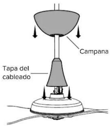
natural_image
Diagram of a cable inserted into a device with arrows indicating direction (no text or symbols)natural_image
Technical line drawing of a mechanical assembly with no visible text or symbolsFig. 2.2
natural_image
Simple line drawing of a connector with an arrow indicating rotation and cable (no text or symbols)REV. D | © 2018 BIG ASS FANS | TODOS LOS DERECHOS RESERVADOS
natural_image
Simple line drawing of a connector with an arrow indicating rotation and cable (no text or symbols)REV. D: © 2018 BIG ASS FANS | TODOS LOS DERECHOS RESERVADOS
2348 Innovation Drive
Lexington, KY 40511
bigassfans.com
+1 855 694 2458
Canada
6300 Northwest Dr, Unit 3
Mississauga, ON L4V 1J7, Canada
bigassfans.com
+1 844 424 5848
Australia
35 French Street
Eagle Farm, Brisbane, QLD 4009
bigassfans.com/au
+61 1300 244 277
Southeast Asia
18 Tampines Industrial Crescent
06-07
Singapore 528 605
bigassfans.com/sg
Singapore: +65 6709 8503
Malaysia: +603 5565 0888
Mexico
Reynosa, Tamps C.P. 88736
http://cebsainc.com/
+52 1 899 925 6398
All Other Geographies
2348 Innovation Drive
Lexington, KY 40511
bigassfans.com
+1 859 233 1271
Models:
FR127A-A2, FR127A-S0, FR127A-U0, FR150A-A2, FR150A-S0, FR150A-U0, FR213A-U0
© 2018 Big Ass Fans
The information contained in this document is subject to change without notice. May be protected by one or more patents listed at www.bigassfans.com/patents Haiku is a trademark of Delta T LLC, registered in the U.S. and/or other countries.
For warranty information, visit www.bigassfans.com/product-warranties

WET

HKU-INST-199-MUL-01
- Universal Mount
- Low Profile Mount
- Standard Mount
- BEFORE YOU START
- Turn Off Power
- √ Prepare Fan Site
- ☑ Gather Tools
- ☑ Select Extension Tube (Universal Mount Only)
- Concrete Ceiling
- Choosing an Extension Tube (Universal Mount Only)
- Ceiling Height
- Ceiling Slope
- Haiku Remote
- Install Airfoils
- Install Lower Cover
- Attach Extension Tube and Wiring Harness
- Install Lower Safety Cable and Ground Wire
- Install Mounting Ball
- Install Mounting Bracket
- Hang Fan
- Wire the Fan
- Install Flat Ceiling Fan Stabilizer
- Secure Safety Cable
- Raise Canopy
- Congratulations!
- Install Mounting Plate and Single Bracket
- Secure Safety Cable
- Wire Fan
- Install Mounting Brackets
- Install Wiring Cover
- Install Airfoils
- Install Lower Cover
- Install Mounting Bracket
- Secure Mount Brace Brackets
- Hang Fan
- Secure Safety Cable
- Wire Fan
- Install Wiring Cover and Trim
- Install Airfoils
- Install Lower Cover
- TROUBLESHOOTING
- FRANÇAIS
- Fixation courte
- Fixation standard
- Montura estándar
- Canada
- Australia
- Southeast Asia
- 06-07
- Mexico
- All Other Geographies
Brand : Big Ass Fans
Model : Haiku Indoor
Category : Fan