62/700 - Lighting NUVO - Free user manual and instructions
Find the device manual for free 62/700 NUVO in PDF.


User questions about 62/700 NUVO
0 question about this device. Answer the ones you know or ask your own.
Ask a new question about this device
Download the instructions for your Lighting in PDF format for free! Find your manual 62/700 - NUVO and take your electronic device back in hand. On this page are published all the documents necessary for the use of your device. 62/700 by NUVO.
USER MANUAL 62/700 NUVO
INSTALLATION AND SAFETY INSTRUCTIONS
IMPORTANT: Read before installing fixture. Retain for future reference.
WARNING: Risk of Fire or Electric Shock
- LED fixture installation requires knowledge of luminaries' electrical systems. If not qualified, do not attempt installation. Contact a qualified electrician.
- To reduce risk of fire and over-heating, secure all connections.
• TURN OFF the electrical power before proceeding.
• The electrical rating of this product is 120V 50/60Hz. - To prevent wiring damage or abrasion, do not expose wiring to edges of sheet metal or other sharp objects.
- Do not make or alter any open holes in an enclosure of wiring or electrical components during installation.
- Not intended for recessed installation in ceilings or soffits.
- For indoor or damp location.
- This product must be installed in accordance with the owner's manual, current electrical codes and/or the current National Electric Code (NEC).
WARRANTY: This product is guaranteed for a 5-year warranty. Any quality issue in normal use within the warranty period, will be repaired or replaced according to the situation and under the condition specifications can be provided. Visit www.Satco.com for full warranty details and dimmer compatibility information.
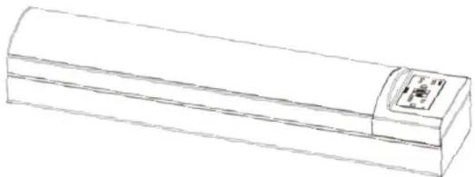
natural_image
Line drawing of a cylindrical object with a small circular label on the top (no text or symbols)18" L x 2 1/5" W x 4 7/16" D (458mm) x (64mm) x (113mm)
| Part Description Quantity | ||
| 1 | LED Module 1 | |
| 2 | GFCI Socket 1 | |
| 3 | Modulator Body 1 | |
| 4 | Machine Screw | 2 |
| 5 | Drywall Anchor | 2 |
| 6 | Wood Screw | 2 |
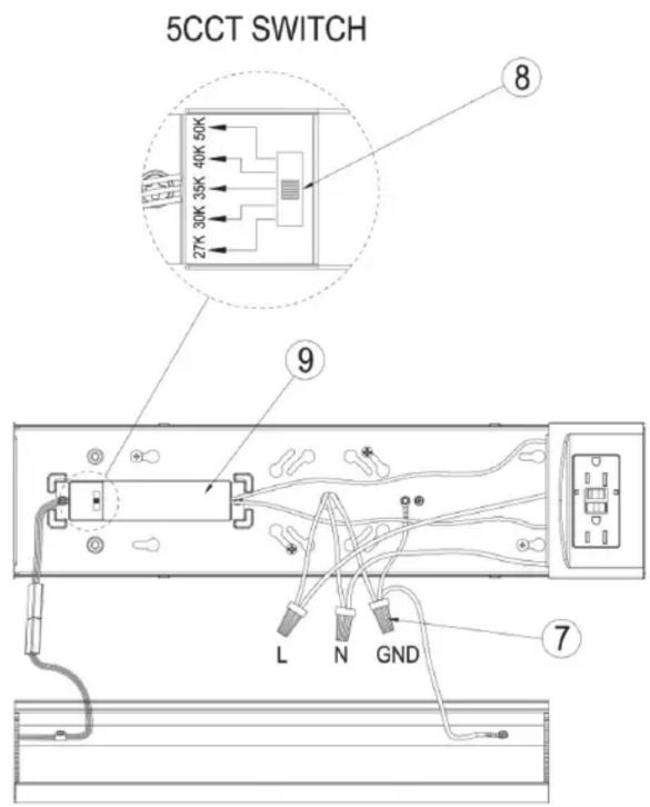
| 7 | Wire Nuts | 3 |
| 8 | 5CCT Switch | 1 |
| 9 | LED Driver | 1 |
INSTALLATION
External Wiring Method
STEP 1: Turn OFF power supply before installation.
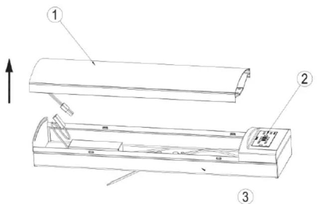
STEP 2: Remove diffuser from housing. Near one end of housing, grasp edge of diffuser and carefully squeeze to release diffuser from housing. Continue down length of diffuser to fully disengage.
text_image
Technical diagram of a device with labeled parts and an upward arrow indicating directionSTEP 3: Remove fixture components and parts. Check that all parts are included.
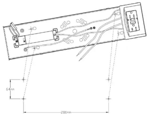
STEP 4: Thread two machine screws into junction box (NOTE: screws must be the same distance apart as keyholes in back of housing assembly).
text_image
64 mm 280 mmINSTALLATION
External Wiring Method (continued)
STEP 5: Hold the fixture housing firmly and connect the green ground wire from the fixture to the bare copper ground wire from the junction box using a wire nut. (If house wiring does not include a ground wire, consult your local electrical code for approved grounding methods).
STEP 6: Use wire nuts to connect the black fixture wire to the black power supply wire and the white (neutral) fixture wire to the white power supply wire.
STEP 7: Hold fixture housing in one hand and with the other hand position wires up into junction box.
STEP 8: Align keyholes on back of fixture housing with screws previously installed in junction box. Lift fixture up, rotate clockwise and tighten screws to secure housing assembly against ceiling.
STEP 9: Installation is complete. Turn power ON.
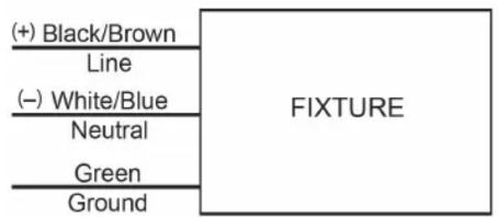
WIRING DIAGRAM
text_image
(+) Black/Brown Line (-) White/Blue Neutral Green Ground FIXTUREInternal Wiring Method
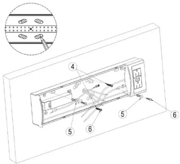
STEP 1: Use machine screws, dry wall anchors and wood screws to secure the wall of the lamp body. Mark holes with a pencil.
text_image
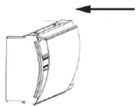
Technical diagram of an electronic device with labeled components and a magnified inset showing assembly details.STEP 3: Attach the light source assembly to the lamp body.
natural_image
Simple line drawing of a rectangular object with a curved internal structure and an arrow pointing right (no text or symbols)STEP 2: Wire the lamp according to the diagram. Adjust the color temperature switch 2700K/3000K/3500K/4000K/5000K to the desired setting.