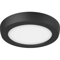
62/1701 - Lighting NUVO - Free user manual and instructions
Find the device manual for free 62/1701 NUVO in PDF.


| Brand | NUVO |
| Model | 62/1701 |
| Product Type | LED Ceiling Light |
| Light Source | Integrated LED |
| Color Temperature | Selectable: 2700K, 3000K, 3500K, 4000K or 5000K via switch |
| Dimming | Compatible with dimmers (list at www.Satco.com) |
| Power Supply | 120 V AC (120-277 V for 0-10 V version) |
| Mounting Type | 3 and 4 inch round or octagonal junction box |
| Usage | Indoor, suitable for damp locations |
| Warranty | 5 years |
| Certifications | FCC Part 15, Class B |
| Safety | Disconnect power before installation; installation by qualified electrician |
| Maintenance and Cleaning | Clean with a soft, dry cloth. Do not use water or chemicals. |
| Repairability | LED non-replaceable; no spare parts available |
| Included Accessories | Mounting plate, wire caps |
| Additional Information | Visit Satco website for compatible dimmer list |
Frequently Asked Questions - 62/1701 NUVO
User questions about 62/1701 NUVO
0 question about this device. Answer the ones you know or ask your own.
Ask a new question about this device
Download the instructions for your Lighting in PDF format for free! Find your manual 62/1701 - NUVO and take your electronic device back in hand. On this page are published all the documents necessary for the use of your device. 62/1701 by NUVO.
USER MANUAL 62/1701 NUVO
CCT SELECTABLE BLINK LED FLUSH FIXTURES
SATCO | NUVO
Models: 62-1700, 62-1701, 62-1702, 62-1703, 62-1704, 62-1705, 62-1706, 62-1707, 62-1710,
62-1711, 62-1712, 62-1713, 62-1714, 62-1715, 62-1716, 62-1717, 62-1718, 62-1719, 62-1720,
62-1721, 62-1722, 62-1723, 62-1724, 62-1725, 62-1726, 62-1727, 62-1728, 62-1729
INSTALLATION AND SAFETY INSTRUCTIONS
IMPORTANT: Read before installing fixture. Retain for future reference.
WARNING: Risk of Fire or Electric Shock
- Disconnect power before installation or maintenance of the fixture.
- To avoid damage, falling, electric shock or fire, do not modify the fixture or replace accessories without confirming with the supplier first.
- Only authorized, qualified personnel should install this fixture and should follow the owner's manual. Any improper installation might cause failure, electric shock, fire or other injury, damage or hazard.
- To prevent fire, this fixture is rated for use in 120VAC.
- 0–10V models are 120/277V. See 0–10V wiring diagram.
- The product is purposed for interior use only, suitable for wet locations.
- Suitable for use with dimmers. Visit www.Satco.com for a list of compatible dimmers.
- Protect the product against direct contact with water.
- For use in environments where an accumulation of non-conductive dust on the fixture may be expected.
- Clean with a soft or damp cloth, making sure the power is OFF.
- Assemble the product only with the use of parts provided and the housing; improper assembly may result in device failing which could damage the product, personal property or cause injury.
- CAUTION: When handling the fixture, do not apply pressure to the LEDs. Hold the fixture by the base only.
The circuit is intended for connection to an external Class 2 supply. Any changes or modifications to this unit not expressly approved by the party responsible for compliance could void the user's authority to operate the equipment.
NOTE: This equipment has been tested and found to comply with the limits for a Class B digital device, pursuant to part 15 of the FCC Rules. These limits are designed to provide reasonable protection against harmful interference in a residential installation. This equipment generates, uses and can radiate radio frequency energy and, if not installed and used in accordance with the instructions, may cause harmful interference to radio communications. However, there is no guarantee that interference will not occur in a particular installation. If this equipment does cause harmful interference to radio or television reception, which can be determined by turning the equipment off and on, the user is encouraged to try to correct the interference by one or more of the following measures:
— Reorient or relocate the receiving antenna.
— Increase the separation between the equipment and receiver.
— Connect the equipment into an outlet on a circuit different from that to which the receiver is connected.
— Consult the dealer or an experienced radio/TV technician for help.
WARRANTY: This product is guaranteed for a 5 year warranty. Any quality issue in normal use within the warranty period, will be repaired or replaced according to the situation and under the condition specifications can be provided. Visit www.Satco.com for full warranty details.
natural_image
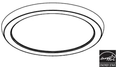
Simple line drawing of two concentric ovals with a small logo in the corner (no text or symbols on the main shapes)CCT Selectable 2700K/3000K/3500K/4000K/5000K
Wiring Diagrams
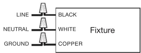
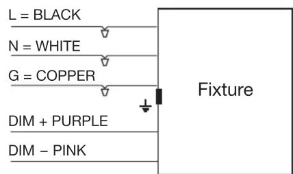
NOTE: 0-10V wiring for models: 62-1718, 62-1719, 62-1728, 62-1729 (120/277V)
INSTALLATION - 3" & 4" Junction Box
(*Fits most 3" and 4" Junction Boxes with a minimum interior cubic volume of 14 in.)
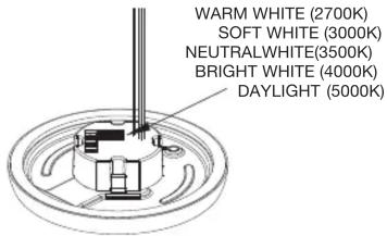
STEP 1: Turn OFF power prior to installation. Before installation, select your preferred CCT by moving the switch to either 2700K, 3000K, 3500K, 4000K or 5000K.
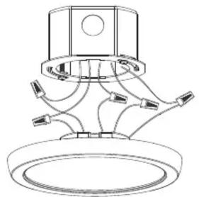
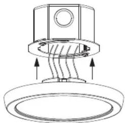
STEP 3: Connect the wires with wiring caps. See wiring diagrams.
natural_image
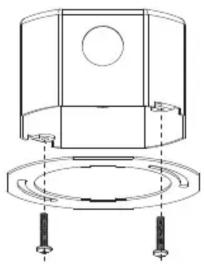
Technical line drawing of a mechanical component with no visible text or symbolsSTEP 2: Screw the mounting plate on the junction box.
natural_image
Technical line drawing of a mechanical component with mounting flange and cylindrical base (no text or symbols)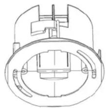
natural_image
Technical line drawing of a mechanical component with concentric rings and mounting holes (no text or symbols)STEP 4: Align the clips with the mounting plate and push the fixture up into junction box. Turn ON power. Installation is complete.
natural_image
Technical line drawing of a mechanical component with curved internal structure and circular base (no text or symbols)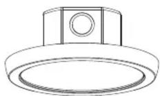
INSTALLATION - 3" & 4" Pancake Junction Box
STEP 1: Turn OFF power prior to installation. Before installation, select your preferred CCT by moving the switch to either 2700K, 3000K, 3500K, 4000K or 5000K.
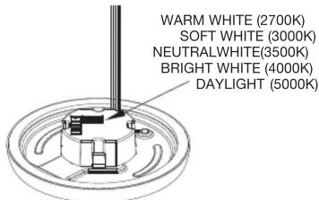
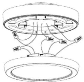
STEP 3: Connect the wires with wiring caps. See wiring diagrams.
natural_image
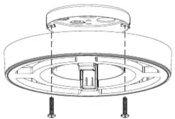
Technical line drawing of a mechanical assembly with no visible text or symbolsSTEP 2: Screw the installation accessory on 3" & 4" pancake junction box.
natural_image
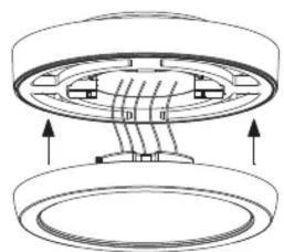
Technical line drawing of a circular mechanical component with mounting feet and internal structure (no text or symbols)STEP 4: Align the clips with the mounting plate and push the fixture up into junction box. Turn ON power. Installation is complete.
natural_image
Technical diagram of a mechanical assembly with two circular components and directional arrows indicating motion (no text or symbols)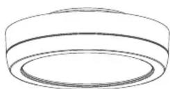
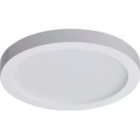
Brand : NUVO
Model : 62/1701
Category : Lighting