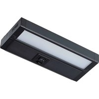
63/520 - Lighting NUVO - Free user manual and instructions
Find the device manual for free 63/520 NUVO in PDF.


| Product Type | Under Cabinet LED Luminaire |
| Brand | NUVO |
| Model | 63/520 (and models 63-500 to 63-525) |
| Power Supply | 120 V / 60 Hz |
| Main Functions | Dimming (HI/LOW/OFF) and color selection |
| Mounting | Direct or keyhole slots |
| Wiring Options | Power cord, fixed connection to junction box, or direct connection to luminaire |
| Multiple Connection | Possible with linking cable (sold separately) |
| Warranty | 5 years |
| Standards | Compliant with applicable electrical codes (NEC) |
| Safety | Installation by a qualified electrician recommended; do not expose to sharp edges |
| Environment | Not designed for wet locations |
| Dimming Compatibility | Information available at www.Satco.com |
Frequently Asked Questions - 63/520 NUVO
User questions about 63/520 NUVO
0 question about this device. Answer the ones you know or ask your own.
Ask a new question about this device
Download the instructions for your Lighting in PDF format for free! Find your manual 63/520 - NUVO and take your electronic device back in hand. On this page are published all the documents necessary for the use of your device. 63/520 by NUVO.
USER MANUAL 63/520 NUVO
LED UNDER CABINET FIXTURE
Models: 63-500, 63-501, 63-502, 63-503, 63-504, 63-505, 63-520, 63-521, 63-522, 63-523, 63-524, 63-525
INSTALLATION AND SAFETY INSTRUCTIONS
IMPORTANT: Read before installing fixture. Retain for future reference.
WARNING: Risk of Fire or Electric Shock
- LED Under Cabinet Fixture installation requires knowledge of luminaries' electrical systems. If not qualified, do not attempt installation. Contact a qualified electrician.
- To reduce risk of fire and over-heating, secure all connections.
• TURN OFF the electrical power before proceeding.
• The electrical rating of this product is 120V/60Hz. - To prevent wiring damage or abrasion, do not expose wiring to edges of sheet metal or other sharp objects.
- Do not make or alter any open holes in an enclosure of wiring or electrical components during installation.
• Not rated for wet locations. - This product must be installed in accordance with the owner's manual, current electrical codes and/or the current National Electric Code (NEC).
WARRANTY: This product is guaranteed for a 5-year warranty. Any quality issue in normal use within the warranty period, will be repaired or replaced according to the situation and under the condition specifications can be provided. Visit www.Satco.com for full warranty details and dimmer compatibility information.
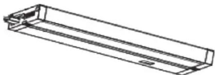
Model # (Color) Dimensions
| 63-500 (Wht), 63-520 (Dk Brz) | 8"L x 3 1/2"W (203mm x 90mm) |
| 63-501 (Wht), 63-521 (Dk Brz) | 11"L x 3 1/2"W (280mm x 90mm) |
| 63-502 (Wht), 63-522 (Dk Brz) | 14"L x 3 1/2"W (355mm x 90mm) |
| 63-503 (Wht), 63-523 (Dk Brz) | 22"L x 3 1/2"W (559mm x 90mm) |
| 63-504 (Wht), 63-524 (Dk Brz) | 28"L x 3 1/2"W (711mm x 90mm) |
| 63-505 (Wht), 63-525 (Dk Brz) | 34"L x 3 1/2"W (863mm x 90mm) |
WIRING DIAGRAM
| (+) Black/BrownLine | FIXTURE |
| (-) White/BlueNeutralGreenGround |
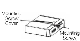
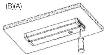
INSTALLATION: Mounting – Direct
STEP 1: Open the two mounting screw covers located on the front edge of the fixture (A).
STEP 2: Place the fixture in desired position and mount with included screws (B).
STEP 3: Close the mounting screw cover.
Mounting - Keyhole
STEP 1: Place the fixture in the desired location, open the front panel using a flat tool to pry it open, and mark the locations of the keyholes through the wiring area (C).
STEP 2: Install (2) screws into the marked locations.
STEP 3: Mount fixture through 2 keyholes on back of device. Tighten screws if required (D).
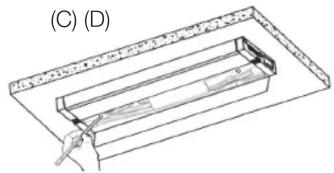
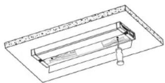
WIRING: Option 1 – Power Cord
STEP 1: Mount the fixture.
STEP 2: Remove the electrical port cover on the INPUT side.
STEP 3: Connect the power cable to the female port on the fixture.
STEP 4: Plug the power cable into a 120 Volt outlet.
STEP 5: Bundle the excess power cord with zip ties or twist ties.
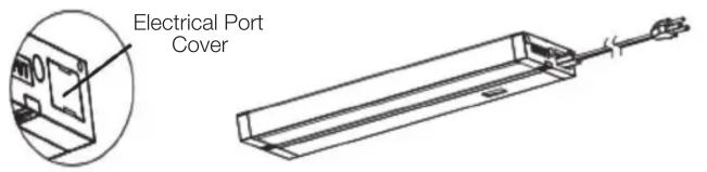
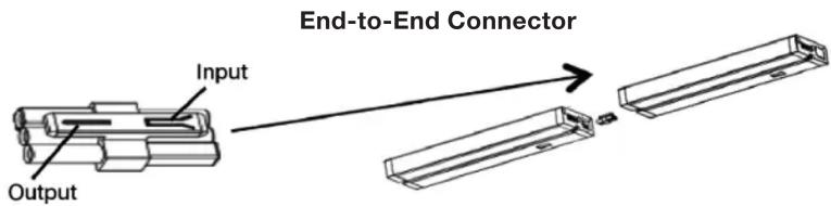
End-to-End Connector

Option 2 – Hardwire to a Junction Box
(sold separately)
STEP 1: Disconnect power from the breaker or fuse box.
STEP 2: Remove the electrical port cover from the INPUT end.
STEP 3: Use the provided end-to-end connector or link cable accessory to link the junction box to the INPUT side of the fixture.
STEP 4: Connect the OUTPUT end of the end-to-end connector to the junction box.
STEP 5: Open the junction box and remove the most convenient of the three knockouts.
STEP 6: Mount the junction box and the fixture to the cabinet.
STEP 7: Attach the 3/8" die-cast connector to the junction box and pull wiring through it.
STEP 8: Connect wiring using above wiring diagram.
STEP 9: Close the junction box.
(continued)
WIRING: Option 3 – Hardwire Direct to Fixture
STEP 1: Disconnect power from the breaker or fuse box.
STEP 2: Remove the most convenient of 3 knockouts and attach the provided 3/8" die-cast connector.
STEP 3: Mount the fixture.
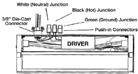
Wiring using FRONT COVER, follow steps 4 – 7 below
STEP 4: Open the front panel of the fixture to access the wiring by using a flat tool to pry open the compartment (A).
STEP 5: Insert the wiring from the power source through the connector and connect them to the corresponding wiring inside the fixture (B). BLACK = Hot, WHITE = Neutral, GREEN = Ground.
STEP 6: Ensure excess wires are settled inside the fixture.
STEP 7: Close the front cover.
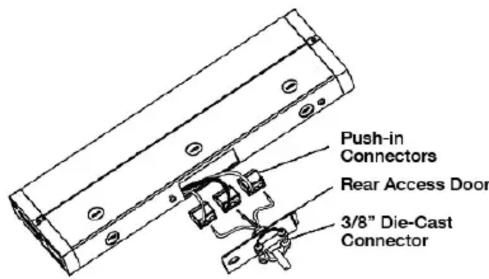
Wiring using REAR ACCESS, follow steps 4 – 7 below (only for 63-503, 63-504, 63-523 and 63-524)
STEP 4: Remove the rear access panel (C) by loosening the rear screw.
STEP 5: Insert the wiring from the power source through the connector and connect them to the corresponding wiring inside the fixture (B). BLACK = Hot, WHITE = Neutral, GREEN = Ground.
STEP 6: Ensure excess wires are settled inside the fixture.
STEP 7: Close the rear access panel.
(A)
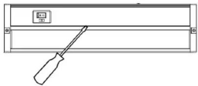
(B)
(C)
CONNECTING MULTIPLE FIXTURES
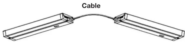
Cable (sold separately)
End-to-End Connector (provided)
STEP 1: Remove electrical port covers on the facing ends.
STEP 2: Connect the cable to the OUTPUT of the first fixture and the INPUT of the next fixture.
| Model # Finish Cable Connector/Length | ||
| 63-511 — End-to-End | ||
| 63-515 White | 6 inches | |
| 63-516 White | 12 inches | |
| 63-517 White | 24 inches | |
| 63-518 White | Male to Female | Extender |
| 63-533 Black | 6 inches | |
| 63-534 Black | 12 inches | |
| 63-535 Black | 24 inches | |
| 63-536 Black | Male to Female | Extender |
NOTE: Maximum number of connected fixtures is 24 units.
OPERATION
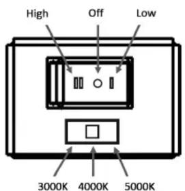
Upon completing the mounting and wiring of this fixture, power can be restored. This fixture includes a Color Selection feature and HI / LOW / OFF Dimming.
These fixtures can also be wired directly to an in-wall dimmer or switch.
For compatibility information, visit www.Satco.com.
ESPAÑOL:
- LED UNDER CABINET FIXTURE
- INSTALLATION AND SAFETY INSTRUCTIONS
- WARNING: RISK OF FIRE OR ELECTRIC SHOCK
- INSTALLATION: MOUNTING – DIRECT
- MOUNTING - KEYHOLE
- WIRING: OPTION 1 – POWER CORD
- OPTION 2 – HARDWIRE TO A JUNCTION BOX
- WIRING: OPTION 3 – HARDWIRE DIRECT TO FIXTURE
- WIRING USING FRONT COVER, FOLLOW STEPS 4 – 7 BELOW
- WIRING USING REAR ACCESS, FOLLOW STEPS 4 – 7 BELOW (ONLY FOR 63-503, 63-504, 63-523 AND 63-524)
- CONNECTING MULTIPLE FIXTURES
- OPERATION
- ESPAÑOL
Brand : NUVO
Model : 63/520
Category : Lighting