65/646R1 - Lighting NUVO - Free user manual and instructions
Find the device manual for free 65/646R1 NUVO in PDF.


User questions about 65/646R1 NUVO
0 question about this device. Answer the ones you know or ask your own.
Ask a new question about this device
Download the instructions for your Lighting in PDF format for free! Find your manual 65/646R1 - NUVO and take your electronic device back in hand. On this page are published all the documents necessary for the use of your device. 65/646R1 by NUVO.
USER MANUAL 65/646R1 NUVO
INSTALLATION AND SAFETY INSTRUCTIONS
IMPORTANT: Read before installing fixture. Retain for future reference.
WARNING
- To reduce the risk of personal injury or property damage from fire, electric shock, falling parts, cuts/abrasions, and other hazards read all warnings and instructions included with and on the fixture and all fixture labels.
- Commercial installation, service and maintenance of luminaries should be performed by a qualified licensed electrician. If you are unsure about the installation or maintenance of the luminaries, consult a qualified licensed electrician and check your local electrical code.
- Turn off electrical power at fuse or circuit breaker before wiring fixture to the power supply.
- Turn off the power when you perform any maintenance.
- All connections should be capped with UL approved wire connectors.
- Verify that supply voltage is correct by comparing it with the luminaire label information.
- Do not install in a hazardous atmosphere, except where the ambient temperature does not exceed the rated operating temperature of the fixture.
- Use min. 90^ supply.
- Damp location rated.
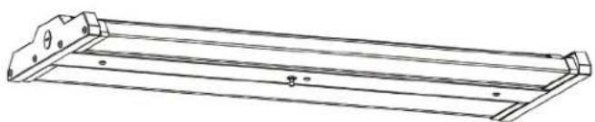
WIRING DIAGRAMS & INSTRUCTIONS
Three dimming functions are available:
- Constant current can be achieved by 0-10VDC dimming
- PWM signal dimming
- Variation of resistance unit dimming
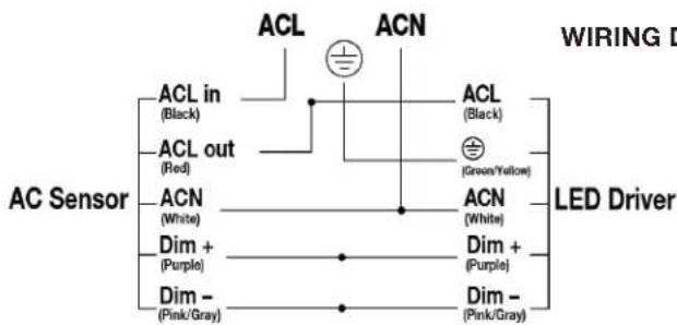
Two wiring methods: 1. Conduit connection
Wiring Instruction
L:Black
N:White
Green/Yellow
DIM+
DIM-
NOTE: For the wire color of DIM+ and DIM-, please check the light label.
Backup Driver Wiring
Please choose the appropriate dimming according to your needs. You can also choose not to use this function.
NOTE: The product can't be connected to a dimming device when it is equipped with Motion Sensor.
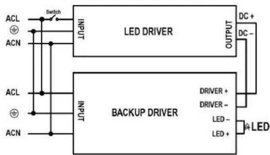
BACKUP WIRING DIAGRAM
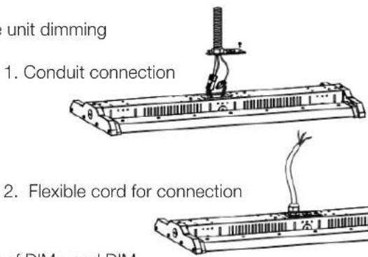
EXTRA ACCESSORY OPTIONS & ASSEMBLY
Wire Guard
STEP 1: Snap the wire guards into the plug of the light-emitting modules and tighten them with screws (Figure 1).
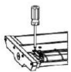
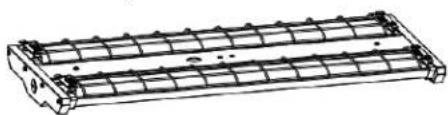
Figure 1
AC Motion Microwave Sensor/Motion PIR Sensor
STEP 1: Use a screwdriver to disassemble the side cover and front cover of the fixture (Figure 2).
STEP 2: Remove the knockout of the side cover and assemble the sensor onto the side cover. Attach the side cover with the sensor back onto the fixture (Figure 3).
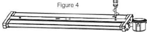
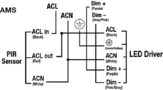
STEP 3: Complete the wiring connection of the sensor according to the marking instructions. Assemble the cover back to the fixture (Figure 4). After the fixture is installed, adjust the lighting direction of the module according to your needs (145^ maximum adjustment from left to right).
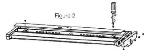
Figure 3

DC Motion Microwave Sensor/Motion PIR Sensor
Option 1
STEP 1: Open the cover with a screw driver (Figure 5).
STEP 2: Remove the knockout on the cover, and install the sensor (Figure 6). Connect the wiring according to the wiring instructions.
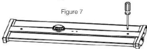
STEP 3: Assemble the cover back onto the fixture (Figure 7). After the fixture light is on, use the remote control to adjust the working mode of the sensor as desired.
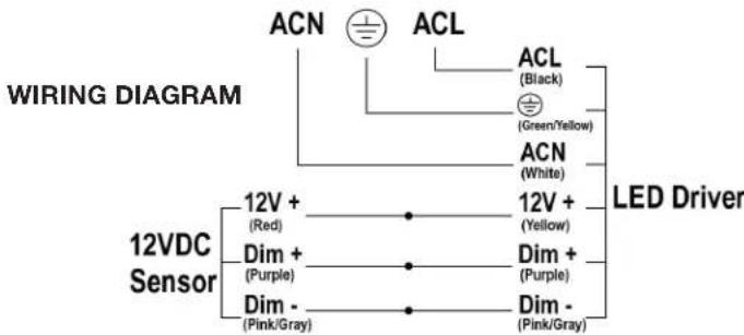
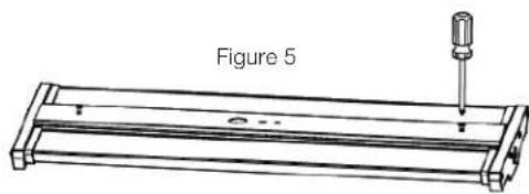

Figure 6
Option 2
STEP 1: Use a screwdriver to remove the 1/2 plug from the sensor (Figure 8).
STEP 2: Twist-lock the DC sensor to the base to make it work properly: use a remote control to adjust the working mode of the sensor as desired (Figure 9).
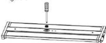
Figure 8
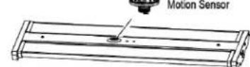
Figure 9
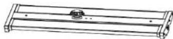
Option 3
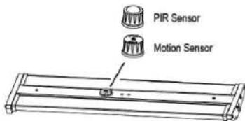
STEP 1: Remove the sensor cap from the base (Figure 10).
STEP 2: Twist-lock the sensor into the base (Figure 11).
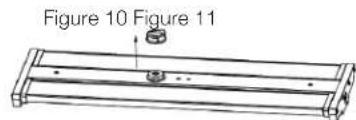
Backup Driver:
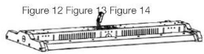
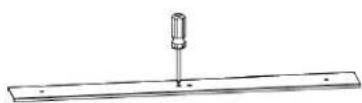
STEP 1: Remove the knockout hole on the back of the fixture, take out the wires from the knockout hole (Figure 12), open the front cover of the fixture, and remove the two knockout holes on the cover (Figure 13).
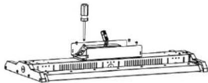
STEP 2: Open the cover of the backup driver box, install the backup driver box at the corresponding position on the back of the fixture (Figure 14), and connect the wires correspondingly according to the marking instructions.
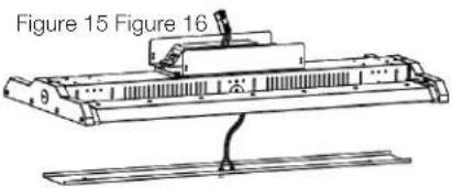
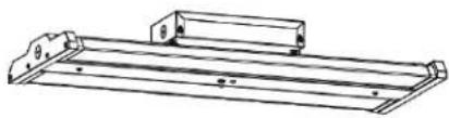
STEP 3: Install the buttons and indicators of backup driver on the front cover of the fixture (Figure 15), then fix the cover to the fixture (Figure 16). After the fixture is installed, adjust the lighting direction of the module according to your needs. (Maximum adjustable angle is 40^ inwards and 145^ outwards).
INSTALLATION: Hanging (Chain)
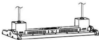
STEP 1: Secure the chain and connect the chain to the fixture. Adjust the chain length as needed (Figure 17).
STEP 2: Wire fixture according to local standards/codes.
STEP 3: After the fixture is installed, adjust the lighting direction of the module according to your needs. 145^ maximum adjustment from left to right (Figure 18).
INSTALLATION: 3 / 4^ NPT
NOTE: If this bracket is used for the fixture, backup driver solution can NOT be chosen.
STEP 1: Mount the bracket on (Figure 19).
STEP 2: Fasten fixture to the bracket (Figure 20).
STEP 3: Wire fixture according to local standards/codes.
STEP 4: Secure side brackets with screw driver (Figure 21).
STEP 5: After the fixture is installed, adjust the lighting direction of the module according to your needs. 145^ maximum adjustment from left to right (Figure 18).
INSTALLATION: Surface/Pendant Mounting
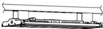
STEP 1: Mount the bracket on rail or ceiling (Figure 22).
STEP 2: Mount bolt on the rail or ceiling, then mount the fixture bracket on the bolt (Figure 23).
STEP 3: Secure fixture to pendant (Figure 24).
STEP 4: Wire fixture according to local standards/codes.
STEP 5: After the fixture is installed, adjust the lighting direction of the module according to your needs. 145^ maximum adjustment from left to right (Figure 18).
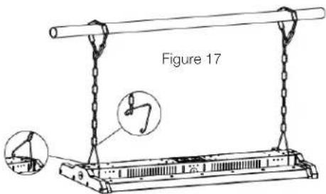
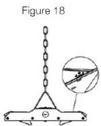
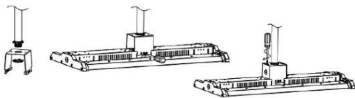
Figure 19 Figure 20 Figure 21
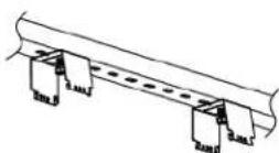
Figure 22
Figure 23 Figure 24