
UNISAW 36‑L352 - Table saw DELTA - Free user manual and instructions
Find the device manual for free UNISAW 36‑L352 DELTA in PDF.

| Product Type | Table Saw |
| Brand | Delta |
| Model | UNISAW 36-L352 |
| Blade Diameter | 254 mm (10 inches) |
| Blade Arbor | 16 mm (5/8 inch) |
| Motor | Single-phase, 3 HP, 230 V, 60 Hz |
| Depth of Cut at 90° | 79 mm (3-1/8 inches) |
| Depth of Cut at 45° | 54 mm (2-1/8 inches) |
| Ripping Capacity (to the right of blade) | 914 mm (36 inches) |
| Ripping Capacity (to the left of blade) | 305 mm (12 inches) |
| Maximum Dado Width | 25.4 mm (1 inch) |
| Blade Tilt | Up to 45° to the left |
| Safety Features | Blade guard, riving knife, anti-kickback device, lockable switch |
| Rip Fence | Included, capacity 914 mm (36 inches) |
| Miter Gauge | Included, stored on side of cabinet |
| Dust Collection | Adapter for 127 mm (5 inch) hose with reducer to 102 mm (4 inch) |
| Power Supply | 230 V, 60 Hz, single-phase, 3 HP |
| Estimated Weight | Approximately 140 kg (310 lbs) |
| Maintenance | Cleaning with compressed air, lubrication of worm gears and trunnions, table wax |
| Warranty | Limited 5 years |
Frequently Asked Questions - UNISAW 36‑L352 DELTA
User questions about UNISAW 36‑L352 DELTA
0 question about this device. Answer the ones you know or ask your own.
Ask a new question about this device
Download the instructions for your Table saw in PDF format for free! Find your manual UNISAW 36‑L352 - DELTA and take your electronic device back in hand. On this page are published all the documents necessary for the use of your device. UNISAW 36‑L352 by DELTA.
USER MANUAL UNISAW 36‑L352 DELTA
10" LEFT TILTING UNISAW®
Penchant à gauche
UNISAW® de 254 mm (10 po)
UNISAW® de 254 mm (10 pulg)
Part No. N061865 - 1-22-10
IMPORTANT SAFETY INSTRUCTIONS
⚠ WARNING: Read all warnings and operating instructions before using any tool or equipment. When using tools or equipment, basic safety precautions should always be followed to reduce the risk of personal injury. Improper operation, maintenance or modification of tools or equipment could result in serious injury and property damage. There are certain applications for which tools and equipment are designed. DELTA Machinery strongly recommends that this product NOT be modified and/or used for any application other than for which it was designed.
If you have any questions relative to its application DO NOT use the product until you have written DELTA Machinery and we have advised you. Contact us online at www.deltaportercable.com or by mail at End User Services, DELTA Machinery, PO Box 2468, Jackson, TN 38302-2468. In Canada, 125 Mural St. Suite 300, Richmond Hill, ON, L4B 1M4) Information regarding the safe and proper operation of this tool is available from the following sources:
• Power Tool Institute, 1300 Sumner Avenue, Cleveland, OH 44115-2851 or online at www.powertoolinstitute.com
• National Safety Council, 1121 Spring Lake Drive, Itasca, IL 60143-3201
- American National Standards Institute, 25 West 43rd Street, 4 floor, New York, NY 10036 www.ansi.org - ANSI 01.1 Safety Requirements for Woodworking Machines
• U.S. Department of Labor regulations www.osha.gov
SAVE THESE INSTRUCTIONS!
SAFETY GUIDELINES - DEFINITIONS
It is important for you to read and understand this manual. The information it contains relates to protecting YOUR SAFETY and PREVENTING PROBLEMS. The symbols below are used to help you recognize this information.
DANGER:
Indicates an imminently hazardous situation which, if not avoided, will result in death or serious injury.
WARNING:
Indicates a potentially hazardous situation which, if not avoided, could result in death or serious injury.
CAUTION:
Indicates a potentially hazardous situation which, if not avoided, may result in minor or moderate injury.
NOTICE :
Used without the safety alert symbol indicates a potentially hazardous situation which, if not avoided, may result in property damage.
GENERAL SAFETY RULES
⚠ WARNING: Failure to follow these rules may result in serious personal injury.
For your own safety, read the instruction manual 1. before operating the machine. Learning the machine's application, limitations, and specific hazards will greatly minimize the possibility of accidents and injury.
Wear eye and hearing protection and always use 2. safety glasses. Everyday eyeglasses are not safety glasses. Use certified safety equipment. Eye protection equipment should comply with ANSI Z87.1 standards. Hearing equipment should comply with ANSI S3.19 standards.
Wear proper apparel. 3. Do not wear loose clothing, gloves, neckties, rings, bracelets, or other jewelry which may get caught in moving parts. Nonslip protective footwear is recommended. Wear protective hair covering to contain long hair.
Do not use the machine in a dangerous environment. 4. The use of power tools in damp or wet locations or in rain can cause shock or electrocution. Keep your work area well-lit to prevent tripping or placing arms, hands, and fingers in danger.
Do not operate electric tools near flammable liquids 5. or in gaseous or explosive atmospheres. Motors and switches in these tools may spark and ignite fumes.
Maintain all tools and machines in peak condition. 6. Keep tools sharp and clean for best and safest performance. Follow instructions for lubricating and changing accessories. Poorly maintained tools and machines can further damage the tool or machine and/or cause injury.
Check for damaged parts. 7. Before using the machine, check for any damaged parts. Check for alignment of moving parts, binding of moving parts, breakage of parts, and any other conditions that may affect its operation. A guard or any other part that is damaged should be properly repaired or replaced with DELTA or factory authorized replacement parts. Damaged parts can cause further damage to the machine and/or injury.
-
Keep the work area clean. Cluttered areas and benches invite accidents.
-
Keep children and visitors away. Your shop is a potentially dangerous environment. Children and visitors can be injured.
-
Reduce the risk of unintentional starting. Make sure that the switch is in the "OFF" position before plugging in the power cord. In the event of a power failure, move the switch to the "OFF" position. An accidental start-up can cause injury. Do not touch the plug's metal prongs when unplugging or plugging in the cord.
-
Use the guards. Check to see that all safety devices are in place, secured, and working correctly to prevent injury.
Remove adjusting keys and wrenches before starting 12. the machine. Tools, scrap pieces, and other debris can be thrown at high speed, causing injury.
-
Use the right machine. Don't force a machine or an attachment to do a job for which it was not designed. Damage to the machine and/or injury may result.
-
Use recommended accessories. The use of accessories and attachments not recommended by DELTA may cause damage to the machine or injury to the user.
-
Use the proper extension cord. Make sure your extension cord is in good condition. When using an extension cord, be sure to use one heavy enough to carry the current your product will draw. An undersized cord will cause a drop in line voltage, resulting in loss of power and overheating. See the Extension Cord Chart for the correct size depending on the cord length and nameplate ampere rating. If in doubt, use the next heavier gauge. The smaller the gauge number, the heavier the cord.
-
Secure the workpiece. Use clamps or a vise to hold the workpiece when practical. Loss of control of a workpiece can cause injury.
Feed the workpiece against the direction of the 17. rotation of the blade, cutter, or abrasive surface. Feeding it from the other direction will cause the workpiece to be thrown out at high speed.
-
Don't force the workpiece on the machine. Damage to the machine and/or injury may result.
-
Don't overreach. Loss of balance can make you fall into a working machine, causing injury.
-
Never stand on the machine. Injury could occur if the tool tips, or if you accidentally contact the cutting tool.
-
Never leave the machine running unattended. Turn the power off. Don't leave the machine until it comes to a complete stop. A child or visitor could be injured.
-
Turn the machine "OFF", and disconnect the machine from the power source before installing or removing accessories, changing cutters, adjusting or changing set-ups. When making repairs, be sure to lock the start switch in the "OFF" position. An accidental start-up can cause injury.
-
Make your workshop childproof with padlocks, master switches, or by removing starter keys. The accidental start-up of a machine by a child or visitor could cause injury.
-
Stay alert, watch what you are doing, and use common sense. Do not use the machine when you are tired or under the influence of drugs, alcohol, or medication. A moment of inattention while operating power tools may result in injury.
-
▲WARNING: Use of this tool can generate and disburse dust or other airborne particles, including wood dust, crystalline silica dust and asbestos dust. Direct particles away from face and body. Always operate tool in well ventilated area and provide for proper dust removal. Use dust collection system wherever possible. Exposure to the dust may cause serious and permanent respiratory or other injury, including silicosis (a serious lung disease), cancer, and death. Avoid breathing the dust, and avoid prolonged contact with dust. Allowing dust to get into your mouth or eyes, or lay on your skin may promote absorption of harmful material. Always use properly fitting NIOSH/OSHA approved respiratory protection appropriate for the dust exposure, and wash exposed areas with soap and water.
ADDITIONAL SPECIFIC SAFETY RULES
WARNING: Failure to follow these rules may result in serious personal injury.
Always use safety glasses. 1. Everyday eyeglasses are not safety glasses. Also use face or dust mask if cutting operation is dusty. All users and bystanders must always wear certified safety equipment:
• ANSI Z87.1 Eye protection (CAN/CSA Z94.3)
• ANSI S12.6 (S3.19) Hearing protection
• NIOSH/OSHA/MSHA respiratory protection.
Do not expose to rain or use in damp locations.2.
- Avoid awkward positions where a sudden slip could cause a hand to move into a saw blade.
Never reach in back of, or around, the cutting tool 4. with either hand to hold down the workpiece.
Keep arms, hands and fingers away 5. from the blade to prevent serious injury.
Use a push stick that is appropriate to the application 6. to push workpieces through the saw. A push stick is a wooden or plastic stick, usually homemade, that should be used whenever the size or shape of the workpiece would cause you to place your hands within 6" (152 mm) of the blade.
- Use hold-downs, jigs, fixtures or feather boards to help guide and control the workpiece. Accessories for use with your tool are available at extra cost from your local dealer or authorized service center. Instructions for making a push stick, a narrow rip auxiliary fence, a push block and feather boards are included in this manual.
- Do not perform ripping, crosscutting or any other operation freehand.
- Stability. Make sure the table saw is firmly mounted to a secure surface before use and does not move.
- Never cut metals, cement board or masonry. Certain man-made materials have special instructions for cutting on table saws. Follow the manufacturer's recommendations at all times. Damage to the saw and personal injury may result.
- The proper throat plate must be in place at all times to reduce the risk of a thrown workpiece and possible injury.
- Use the correct saw blade for the intended operation. The blade must rotate toward the front of the saw. Always tighten the blade arbor nut securely. Before use, inspect the blade for cracks or missing teeth. Do not use a damaged or dull blade.
Never attempt to free a stalled saw blade without first 13. turning the machine off and disconnecting the saw from the power source. If a workpiece or cut-off piece becomes trapped inside the blade guard assembly, turn saw off and wait for blade to stop before lifting the blade guard assembly and removing the piece.
- Never start the machine with the workpiece against the blade to reduce the risk of a thrown workpiece and personal injury.
- Never have any part of your body in line with the path of the saw blade. Personal injury may occur.
- Never perform layout, assembly or set-up work on the table/work area when the machine is running. A sudden slip could cause a hand to move into the blade. Severe injury can result.
- Clean the table/work area before leaving the machine. Lock out the switch and disconnect from the power source to prevent unauthorized use.
- Do not leave a long board (or other workpiece) unsupported so the spring of the board causes it to shift on the table resulting in loss of control and possible injury. Provide proper support for the workpiece, based on its size and the type of operation to be performed. Hold the work firmly against the fence and down against the table surface.
- If your saw makes an unfamiliar noise or if it vibrates excessively, cease operating immediately, turn unit off and disconnect from power source until the problem has been located and corrected. Contact a DELTA factory service center, a DELTA authorized service center or other qualified service personnel if the problem can not be found.
- Use recommended accessories. The use of improper accessories may cause risk of personal injury.
- Do not operate this machine until it is completely assembled and installed according to the instructions. A machine incorrectly assembled can cause serious injury.
- Obtain advice from your supervisor, instructor, or another qualified person if you are not thoroughly familiar with the operation of this machine. Knowledge is safety.
- Additional information regarding the safe and proper operation of power tools (i.e., a safety video) is available from the Power Tool Institute, 1300 Sumner Avenue, Cleveland, OH 44115-2851 (www.powertoolinstitute.com). Information is also available from the National Safety Council, 1121 Spring Lake Drive, Itasca, IL 60143-3201. Please refer to the U.S. Department of Labor OSHA 1910.213 Regulations.
SAVE THESE INSTRUCTIONS.
Refer to them often and use them to instruct others.
TERMINOLOGY
Terms: the following terms will be used throughout the manual and you should become familiar with them.
- Through-cut refers to any cut that completely cuts through the workpiece.
- Non through-cut refers to any cut that does not completely cut through the workpiece.
- Push stick refers to a wooden or plastic stick, usually homemade, that is used to push small workpiece through the saw and keeps the operator's hands clear of the blade.
- Kickback occurs when the saw blade binds in the cut and violently thrusts the workpiece back toward the operator.
- Freehand refers to cutting without the use of a miter gauge or rip fence or any other means of guiding or holding the workpiece other than the operator's hand.
WARNING: Never perform freehand cutting.
- Plunge cutting refers to blind cuts in the workpiece made by either raising the blade through the workpiece or lowering the workpiece down to the blade.
WARNING: Never perform plunge cutting.
- Resawing - Flipping material to make a cut the saw is not capable of making in one pass.
⚠ WARNING: Resawing is not recommended.
- Cove cutting - Coving is an operation where the work is fed at an angle across the blade.
⚠ WARNING: To reduce the risk of personal injury, do not perform cove cutting because table saw blades are not designed for the excessive side loading needed.
SAW BLADE GUARD ASSEMBLY, ANTI-KICKBACK ASSEMBLY AND RIVING KNIFE
Your table saw is equipped with a blade guard assembly, anti-kickback assembly and riving knife that covers the blade and reduces the possibility of accidental blade contact. The riving knife is a flat plate that fits into the cut made by the saw blade and effectively fights kickback by lessening the tendency of the blade to bind in the cut. The blade guard assembly and anti-kickback assembly can only be used when making through cuts that sever the wood. When making rabbets and other cuts that make non through cuts, the blade guard assembly and anti-kickback assembly must be removed and riving knife lowered to the non through cut position marked on the riving knife. Two anti-kickback pawls are located on the sides of the riving knife that allow the wood to pass through the blade in the cutting direction but reduce the possibility of the material being thrown backwards toward the operator.
Use all components of the guarding system (blade guard assembly, riving knife and anti-kickback assembly) for every operation for which they can be used including all through cutting. If you elect not to use any of these components for a particular application exercise additional caution regarding control of the workpiece, the use of push sticks, the position of your hands relative to the blade, the use of safety glasses, the means to avoid kickback and all other warnings contained in this manual and on the saw itself. Replace the guarding systems as soon as you return to through cutting operations. Keep the guard assembly in working order.
MAKING A PUSH STICK
In order to operate your table saw safely you must use a push stick whenever the size or shape of the workpiece would cause your hands to be within 6" (152 mm) of the saw blade or other cutter. A push stick is included with this saw.
No special wood is needed to make additional push-sticks as long as it's sturdy and long enough. A length of 15.7" (400 mm) is recommended with a notch that fits against the edge of the workpiece to prevent slipping. It's a good idea to have several push sticks of the same length [15.7" (400 mm)] with different size notches for different workpiece thicknesses.
See the end of the English section for a picture of a push stick. The shape can vary to suit your own needs as long as it performs its intended function of keeping your hands away from the blade.
KICKBACKS
Kickbacks can cause serious injury. A kickback occurs when a part of the workpiece binds between the saw blade and the rip fence, or other fixed object, and rises from the table and is thrown toward the operator. Kickbacks can be avoided by attention to the following conditions.
How to avoid them and protect yourself from possible injury
A. Be certain that the rip fence is parallel to the saw blade.
B. Do not rip by applying the feed force to the section of the workpiece that will become the cut-off (free) piece. Feed force when ripping should always be applied between the saw blade and the fence; use a push stick for narrow work, 6" (152 mm) wide or less.
C. Keep saw blade guard assembly, riving knife and anti-kickback assembly in place and operating properly. If anti-kickback assembly is not operational, return your unit to the nearest authorized DELTA service center for repair. The riving knife must be in alignment with the saw blade and the anti-kickback assembly must stop a kickback once it has started. Check their action before ripping by pushing the wood under the anti-kickback assembly. The teeth must prevent the wood from being pulled toward the front of the saw.
D. Plastic and composite (like hardboard) materials may be cut on your saw. However, since these are usually quite hard and slippery, the anti-kickback pawls may not stop a kickback. Therefore, be especially attentive to following proper set up and cutting procedures for ripping.
E. Use saw blade guard assembly, anti-kickback assembly and riving knife for every operation for which it can be used, including all through-sawing.
F. Push the workpiece past the saw blade prior to release.
G. Never rip a workpiece that is twisted or warped, or does not have a straight edge to guide along the fence.
H. Never saw a large workpiece that cannot be controlled.
I. Never use the fence as a guide or length stop when crosscutting.
J. Never saw a workpiece with loose knots, flaws, nails or other foreign objects.
K. Never rip a workpiece shorter than 10" (254 mm).
L. Never use a dull blade – replace or have resharpened.
⚠ WARNING: Some dust created by power sanding, sawing, grinding, drilling, and other construction activities contains chemicals known to the State of California to cause cancer, birth defects or other reproductive harm. Some examples of these chemicals are:
- Lead from lead-based paints,
• Crystalline silica from bricks and cement and other masonry products, and
• Arsenic and chromium from chemically-treated lumber (CCA).
Your risk from these exposures varies, depending on how often you do this type of work. To reduce your exposure to these chemicals: work in a well-ventilated area, and work with approved safety equipment, such as those dust masks that are specially designed to filter out microscopic particles.
- Avoid prolonged contact with dust from power sanding, sawing, grinding, drilling, and other construction activities. Wear protective clothing and wash exposed areas with soap and water. Allowing dust to get into your mouth, eyes, or lay on the skin may promote absorption of harmful chemicals.
⚠ WARNING: Use of this tool can generate and/or disburse dust, which may cause serious and permanent respiratory or other injury. Always use NIOSH/OSHA approved respiratory protection appropriate for the dust exposure. Direct particles away from face and body. Always operate tool in well-ventilated area and provide for proper dust removal. Use dust collection system wherever possible.
SAVE THESE INSTRUCTIONS
POWER CONNECTIONS
A separate electrical circuit should be used for your machines:
FOR THREE HORSEPOWER, SINGLE PHASE UNITS
A suitable circuit should not be less than AWG12/3 wiring where the ground wire is attached to an earth ground. The circuit should be protected by a circuit breaker or time delay fuse.
FOR FIVE HORSEPOWER, SINGLE PHASE UNITS
The circuit should not be less than #10 wire and should be protected with a 40 Amp time delay fuse.
NOTE: Time delay fuses should be marked "D" in Canada and "T" in the US. If an extension cord is used, use only 3-wire extension cords which have 3-prong grounding type plugs and matching receptacle which will accept the machine's plug. Before connecting the machine to the power line, make sure the switch is in the "OFF" position and be sure that the electric current is of the same characteristics as indicated on the machine. All line connections should make good contact. Running on low voltage will damage the machine.
▲ DANGER: SHOCK HAZARD. Do not expose the machine to rain or operate the machine in damp locations.
MOTOR SPECIFICATIONS
All Unisaw motors are rated for 60 HZ alternating current, but voltage and HP varies according to model:
Model: Specifications:
36-L336, 36-L352 3HP, 230V single phase motor
36-L552 5 HP, 230V single phase motor
36-L552LVC 5 HP, 230V/460V three phase, dual voltage motor
▲ DANGER: Before connecting the machine to the power source, make sure that the switch is in the “OFF” position.
GROUNDING INSTRUCTIONS
▲ DANGER: SHOCK HAZARD. This machine must be grounded while in use to protect the operator from electric shock.
1. All grounded, cord-connected machines:
In the event of a malfunction or breakdown, grounding provides a path of least resistance for electric current to reduce the risk of electric shock. This machine is equipped with an electric cord having an equipment-grounding conductor and a grounding plug. The plug must be plugged into a matching outlet that is properly installed and grounded in accordance with all local codes and ordinances.
Do not modify the plug provided - if it will not fit the outlet, have the proper outlet installed by a qualified electrician.
Improper connection of the equipment-grounding conductor can result in risk of electric shock. The conductor with insulation having an outer surface that is green with or without yellow stripes is the equipment-grounding conductor. If repair or replacement of the electric cord or plug is necessary, do not connect the equipment-grounding conductor to a live terminal.
Check with a qualified electrician or service personnel if the grounding instruction are not completely understood, or if in doubt as to whether the machine is properly grounded.
Use only 3-wire extension cords that have 3-prong grounding type plugs and matching 3-conductor receptacles that accept the machine's plug.
Repair or replace damaged or worn cord immediately.
▲DANGER: SHOCK HAZARD. In all cases, make certain that the receptacle in question is properly grounded. If you are not sure, have a qualified electrician check the receptacle.
- Grounded, cord-connected machines intended for use on a supply circuit having a nominal rating between 150 - 250 volts, inclusive:
If the machine is intended for use on a circuit that has an outlet that looks like the one illustrated in Fig. A or Fig. B, the machine will have a grounding plug that looks like the plug illustrated in Fig. A or Fig. B. Make sure the machine is connected to an outlet having the same configuration as the plug. No adapter is available or should be used with this machine. If the machine must be re-connected for use on a different type of electric circuit, the re-connection should be made by qualified service personnel; and after re-connection, the machine should comply with the National Electric Code and all local codes and ordinances.
NOTE: The plug for the 3 HP model looks like the plug illustrated in Fig. A. Make sure the 3 HP machine is connected to an outlet having the same configuration as the plug.
NOTE: The plug for the 5 HP model looks like the plug illustrated in Fig. B. Make sure the 5 HP machine is connected to an outlet having the same configuration as the plug.
- Permanently connected machines:
If the machine is intended to be permanently connected, all wiring must be done by a qualified electrician and conform to the National Electric Code and all local codes and ordinances.
THREE PHASE OPERATION: Three phase machines are not supplied with a power cord and must be permanently connected to a building's electrical system. Extension cords can't be used with a three phase machine.
LVC MAGNETIC MOTOR CONTROL: If you purchased a machine that has a Low Voltage Magnetic Motor Control System, refer to its instruction manual for installation guidance.
EXTENSION CORDS
⚠ WARNING: Use proper extension cords. Make sure your extension cord is in good condition and is a 3-wire extension cord which has a 3-prong grounding type plug and matching receptacle which will accept the machine's plug. When using an extension cord, be sure to use one heavy enough to carry the current of the machine. An undersized cord will cause a drop in line voltage, resulting in loss of power and overheating. Fig. C, shows the correct gauge to use depending on the cord length. If in doubt, use the next heavier gauge. The smaller the gauge number, the heavier the cord.
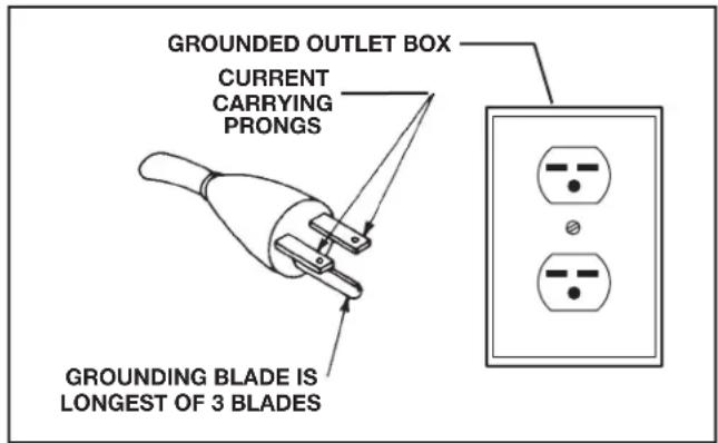
FIG. A
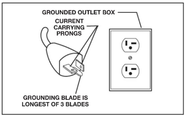
FIG. B
| MINIMUM GAUGE EXTENSION CORDRECOMMENDED SIZES FOR USE WITH STATIONARY ELECTRIC MACHINES | |||
| Ampere Rating | Volts | Total Length of Cord in Feet | Gauge of Extension Cord |
| 0-6 240 | up to 50 18 AWG | ||
| 0-6 240 | 50-100 16 AWG | ||
| 0-6 240 | 100-200 | 16 AWG | |
| 0-6 240 | 200-300 | 14 AWG | |
| 6-10 | 240 | up to 50 18 AWG | |
| 6-10 | 240 50-100 16 AWG | ||
| 6-10 | 240 100-200 | 14 AWG | |
| 6-10 | 240 200-300 | 12 AWG | |
| 10-12 | 240 | up to 50 16 AWG | |
| 10-12 | 240 50-100 16 AWG | ||
| 10-12 | 240 100-200 | 14 AWG | |
| 10-12 | 240 200-300 | 12 AWG | |
| 12-16 | 240 | up to 50 | 14 AWG |
| 12-16 | 240 50-100 12 AWG | ||
| 12-16 | 240 | GREATER THAN 100 FEET NOT RECOMMENDED | |
| 16-20 | 240 | up to 50 | 10 AWG |
| 16-20 | 240 | GREATER THAN 50 FEET NOT RECOMMENDED | |
Fig. C
FUNCTIONAL DESCRIPTION
FOREWORD
The DELTA Unisaw is a 10" (254 mm) left-tilting saw with a 5/8" (16 mm) arbor.
36-L336; 36-L352: Comes with a 3 HP motor and a 36" (914 mm) rip capacity fence.
36-L552: Comes with a 5 HP motor and a 52" (1321 mm) rip capacity fence.
SPECIFICATIONS for 36-L336/ 36-L352 / 36-L552 saws
| Max depth of cut at 90 degrees: | 3-1/8" (79 mm) |
| Max depth of cut at 45 degrees: | 2-1/8" (54 mm) |
| Max rip to right of blade: | |
| 52" (1.3 m) rip fence models | 52" (1321 mm) |
| 36" (914 mm) rip fence models | 36" (914 mm) |
| Max rip to left of blade: | 12" (305 mm) |
| Max width of dado: | 1" (25.4 mm) |
NOTICE: The manual cover illustrates the current production model. All other illustrations contained in the manual are representative only and may not depict the actual labeling or accessories included. These are intended to illustrate technique only.
CARTON CONTENTS
- Saw body (not shown)
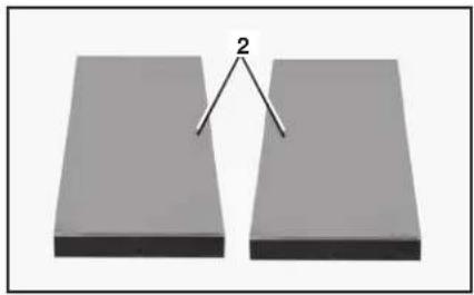
- Right and left extension wings
- 5" (127 mm) to 4" (100 mm) reducer
- M12 hex head screw (6)
- M12 lockwasher (6)
- 5/16-18 x 1" flat head socket screws (2)
- 5/16-18 flange nut (2)
- 5/16" External Tooth Washer
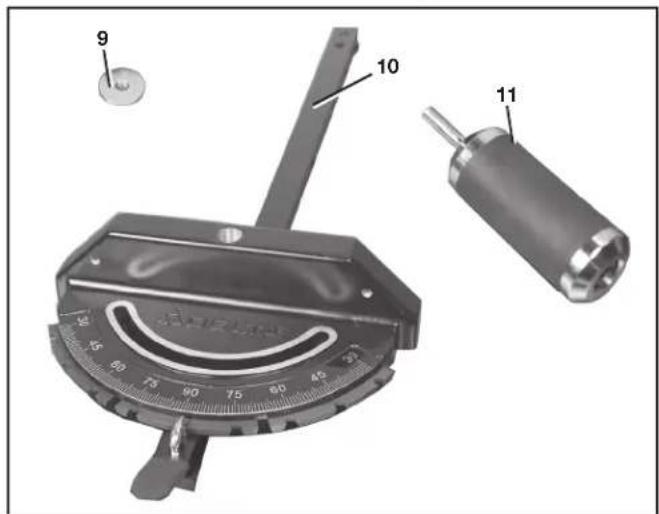
- Washer
- Miter gauge body
- Miter gauge handle
natural_image
Two rectangular blocks with a triangular pointer labeled '2' pointing to the middle block (no text or symbols on the blocks themselves)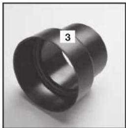
natural_image
Close-up of a black cylindrical mechanical part with a flanged end, labeled '3' in the corner (no other text or symbols visible)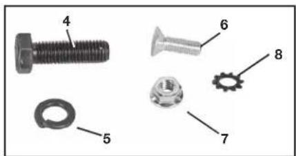
- Anti-kickback assembly
- Special arbor nut
- Blade guard assembly
- Arbor wrench
- Push stick
- T-handle 5/32 hex wrench
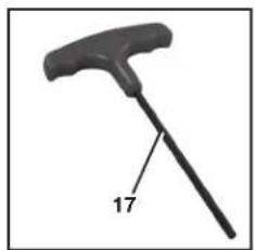
natural_image
Black mechanical tool with a handle and labeled number 17 (no text or symbols on the object itself)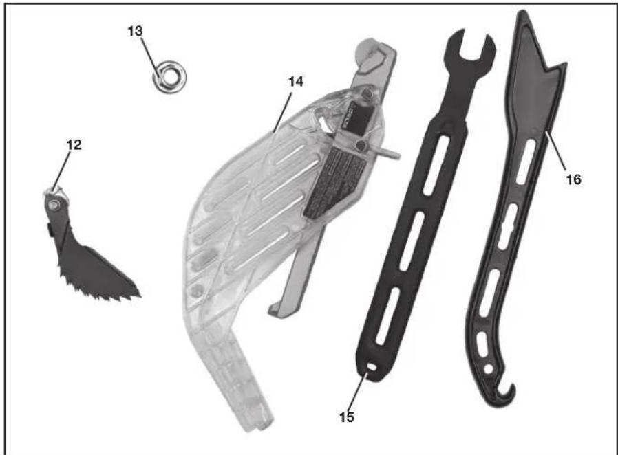
UNPACKING AND CLEANING
Carefully unpack the machine and all loose items from the shipping container(s). Remove the rust-preventative oil from unpainted surfaces using a soft cloth moistened with mineral spirits, paint thinner or denatured alcohol.
△CAUTION: Do not use highly volatile solvents such as gasoline, naphtha, acetone or lacquer thinner for cleaning your machine.
After cleaning, cover the unpainted surfaces with a good quality household floor paste wax.
REMOVE SHIPPING FOAM
- Open the motor cover (A) Fig. 1. First, remove the hex socket head screw (B) with a 5/16 hex wrench.
- Press firmly just above the recessed area on side of cover at (Z) Fig. 1 with the palm of your hand and the motor cover should rotate to the left.
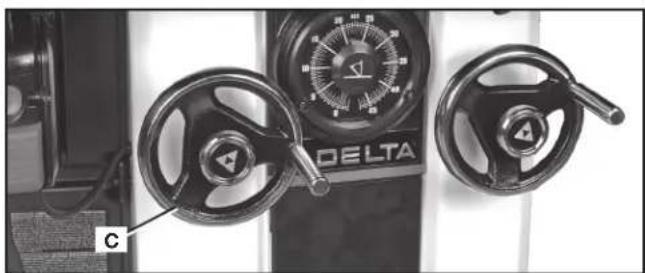
- Turn blade raising wheel (C) Fig. 2 and raise the arbor.
- This will raise the motor (D) Fig. 3 out of the way of the foam block (E).
- Remove foam block.
- Remove reducer. (Located next to foam block.)

FIG. 1
natural_image
Close-up of a Delta motor control panel with two rotary knobs and a dial (no visible text or symbols)FIG. 2
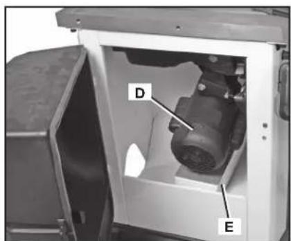
FIG. 3
ASSEMBLY
⚠ WARNING: To reduce the risk of injury, turn unit off and disconnect it from power source before installing and removing accessories, before adjusting or when making repairs. An accidental start-up can cause injury.
ASSEMBLY TOOLS REQUIRED
- 18 mm and 1/2" open-end or socket wrench (not supplied)
• 3/16" hex wrench (not supplied)
ASSEMBLY TIME ESTIMATE
Assembly for this machine takes approximately 2 hours.
SECURING SAW TO A PERMANENT LOCATION
If you desire, you can attach your saw permanently to the floor by drilling holes at four locations provided in the base of the saw (two are shown at (A) Fig. 4).
WARNING: RISK OF INJURY FROM LIFTING. Serious injury can result from attempting to lift too heavy an object. The machine is too heavy to be lifted by one person. Obtain assistance from others before lifting.
WARNING: PINCH HAZARD. Be sure not place toes or fingers underneath the base of the Unisaw while moving. Lift the saw from underneath the table, before assembly, or the wings and extension table after assembly.
EXTENSION WINGS
NOTE: Be sure to remove switch and switch mounting hardware from its shipping location. Switch will be mounted to extension wing.
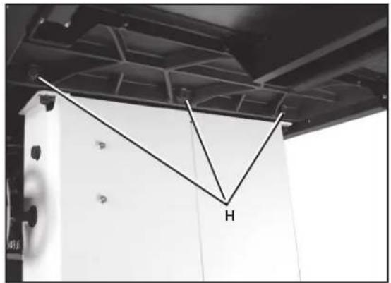
- Align the three holes in the one extension wing with the three holes in the side of the saw table. Assembled wing shown in Fig. 7.
- Place an M12 lockwasher on an M12 hex head screw. Insert the screw through the hole in the extension wing and thread the screw into the threaded hole in the side of the table. FINGER TIGHTEN ONLY. Repeat this process for the two remaining holes in the extension wing and saw table.
NOTE: Ensure that the front edge of the wing is flush with or slightly behind the front edge of the table.
-
Use a straight edge to level the extension wing with the saw table before tightening the three bolts (H) Fig. 7. Use an 18 mm open-end wrench and start with a bolt on one side.
-
Align the table and wing making sure they are level and tighten that side bolt. Move to the middle bolt and follow the same procedure. Finish with the bolt on the other end.
-
Place the other extension wing on the other side of the saw in the same manner.
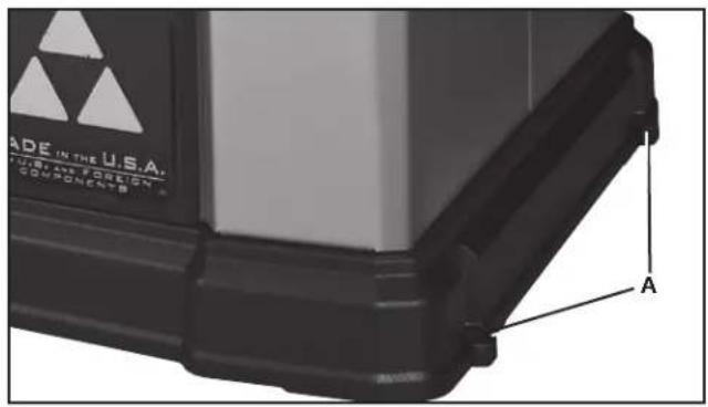
FIG. 4
natural_image
Interior view of a ceiling-mounted industrial or mechanical assembly with a V-shaped metal bracket and labeled component 'H' (no text or symbols beyond the label)FIG. 7
SWITCH
Switch is mounted underneath the front edge of the left extension wing. To mount:
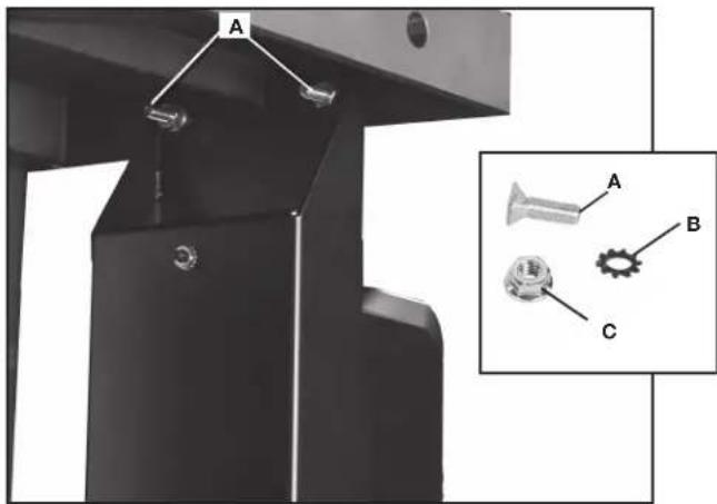
- Insert two 5/16-18 x 1" flat head hex socket screws (A) Fig. 8 through holes in front of wing and then through switch mounting holes.
- Place two 5/16" external tooth washers (B) Fig. 8 on the screws and secure screws from under the extension wing using two 5/16-18 flange nuts (C).
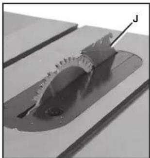
ANTI-KICKBACK, RIVING KNIFE AND BLADE GUARD ASSEMBLIES
The riving knife (J) Fig. 9 comes installed in the low, non-through cutting position.
To assemble the anti-kickback and blade guard assemblies, the riving knife must be in the raised position as shown in Fig. 10. (See Riving Knife Operation and Adjustment section for how to raise and lower the riving knife.)
ANTI-KICKBACK ASSEMBLY
⚠ WARNING: To reduce the risk of serious personal injury, the anti-kickback assembly must be in place for all possible cuts.
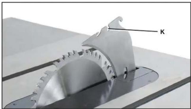
- Locate the anti-kickback mounting hole (K) Fig. 10 at the top of the riving knife (J) Fig. 9.
- Slide the anti-kickback assembly (L) along the top of the riving knife until the stem (M) Fig. 11 locates the slot above the mounting hole.
- Depress the stem (M) on the anti-kickback assembly to allow the assembly to drop into the hole (K). Push down on the anti-kickback assembly until it snaps into place and locks.
NOTE: Pull up on the anti-kickback assembly to ensure it has locked into place.
- To remove anti-kickback assembly: Depress the stem (M) Fig. 11 on the anti-kickback assembly and pull it up off the riving knife.
natural_image
Mechanical assembly with labeled parts A, B, and C, showing a bracket and mounting base (no text or symbols beyond labels)FIG. 8

natural_image
Close-up of a mechanical component with a circular cutout and flange, mounted on a workbench (no visible text or symbols)FIG. 9
natural_image
Close-up of a mechanical component with gear-like structure and labeled 'K' (no other text or symbols visible)FIG. 10
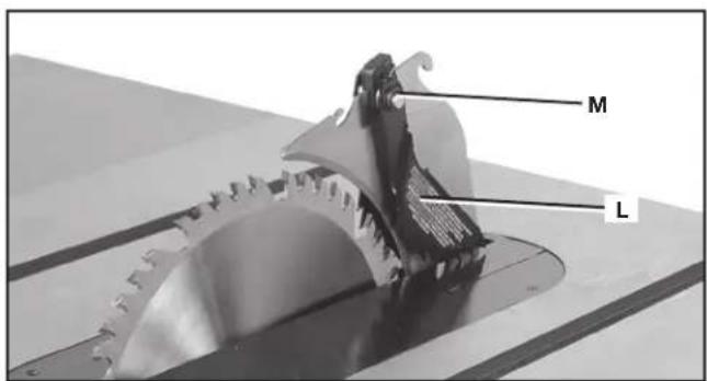
FIG. 11
BLADE GUARD ASSEMBLY
To attach blade guard assembly:
⚠ WARNING: To reduce the risk of serious personal injury, the blade guard assembly must be in place for all possible cuts.
- While holding the blade guard assembly (N) in a vertical position, slide the locating pin (O) into the riving knife slot (P) centering the riving knife within the v-shaped notch in the top guard.
- Rotate the blade guard assembly towards the front of the saw while keeping the pin (O) at the top of the riving knife slot. Rotate until the blade guard assembly is parallel to the table. See Fig. 13.
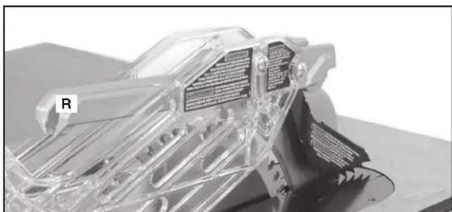
- While holding down on the front of the metal portion of the guard (X), press the blade guard lock lever (Q) Fig. 13 down until it snaps into the locked position, as shown in Fig. 14. Check to make sure the guard is locked onto the riving knife by pulling on the guard at (R) Fig. 14. If the guard is not locked the blade guard lock lever will flip up to the unlocked position, as shown in Fig. 13.
To remove the blade guard assembly:
- Lift the blade guard assembly lock lever (Q) Fig. 13 to the unlocked position.
- Rotate the guard back and slide pin from riving knife slot.
MITER GAUGE ASSEMBLY
To assemble the miter gauge:
- Place washer (S) Fig. 15 on threaded post at end of miter gauge handle (T).
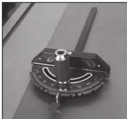
- Tighten threaded post into hole (U) on miter gauge body. Assembled miter gauge shown in Fig. 16.
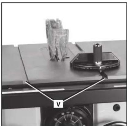
- Insert miter gauge bar end into either miter gauge slot (V) on table (Fig. 17).
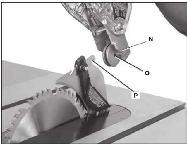
FIG. 12
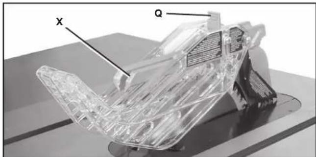
FIG. 13
natural_image
3D rendered mechanical component with transparent internal structure and labeled section R (no readable text or symbols)FIG. 14
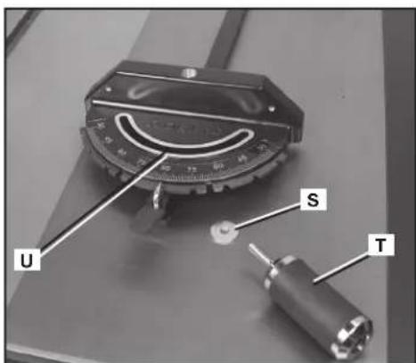
FIG. 15
natural_image
Close-up of a precision measurement tool with a central knob and scale markings (no visible text or symbols)FIG. 16
natural_image
Close-up of a mechanical testing setup with a labeled component 'V' and a cylindrical tool on top (no readable text or symbols)FIG. 17
MITER GAUGE STORAGE
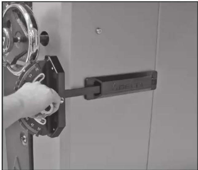
The miter gauge can be stored on the side of the Unisaw cabinet as shown in Fig. 17A.
natural_image
Close-up of a hand operating a SDELTA lock mechanism with a metal frame (no visible text or symbols)FIG. 17A
DUST PORT REDUCER
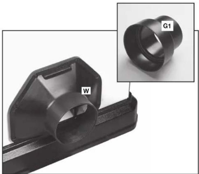
The Unisaw comes with a 5" (127 mm) dust hose adaptor (W) Fig. 18 installed. Also included is a 5" (127 mm) to 4" (102 mm) dust port reducer (G1).
To install the dust port reducer, firmly slide the reducer (G1) Fig. 18 onto the dust hose adaptor (W).
FENCE SYSTEM
Before using the saw or making other adjustments, install and align the fence included, according to the fence instruction manual.
Follow all fence operating and safety rules found in Machine Use section in the back of this manual.
natural_image
Close-up of a black plastic mechanical component with a labeled part 'W' and an inset image showing a ring labeled 'G1' (no text or symbols on the main subject)FIG. 18
OPERATION
OPERATIONAL CONTROLS AND ADJUSTMENTS
⚠ WARNING: To reduce the risk of personal injury, turn unit off and disconnect it from power source before installing and removing accessories, before adjusting or when making repairs. An accidental start-up can cause injury.
STARTING AND STOPPING THE SAW
⚠ WARNING: Make sure that the saw has been turned "OFF" before plugging cord into outlet. Do not touch the plug's metal prongs when unplugging or plugging in the cord.
- The POWER switch (X) Fig. 19 is located underneath the front left extension wing. To turn the saw "ON", push the round button (X) Fig. 19.
- To turn the saw "OFF", push the button (Y) Fig. 19.
LOCKING SWITCH IN THE "OFF" POSITION
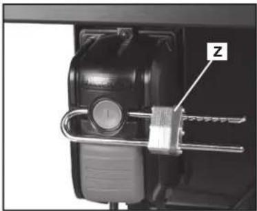
IMPORTANT: When the machine is not in use, the saw should be turned off and the "ON" button locked out to prevent unauthorized use. To lock out "ON" button, use a standard long shackle lock (Z) Fig. 20, with a shackle that is at least 2-3/4" (70 mm) long and with shackle posts no larger than 9/32" (7 mm) thick.
⚠ WARNING: In the event of a power outage (such as a breaker or fuse trip), always move the switch to the "OFF" position until the main power is restored.
OVERLOAD PROTECTION
Your saw is supplied with overload protection. If the motor shuts off or fails to start due to overloading (cutting stock too fast, using a dull blade, using the saw beyond its capacity, etc.) or low voltage, let the motor cool three to five minutes. The overload will automatically reset itself and the machine can then be started again by pressing the "ON" button.
NOTICE: If the motor continually shuts off due to overloading, contact a qualified electrician.
RAISING AND LOWERING THE BLADE
Raise or lower the blade with the left handwheel (AA) Fig. 21. Before raising or lowering the blade, be sure to loosen the lock knob (BB) Fig. 21 by turning it counterclockwise.
To raise the saw blade, turn the handwheel (AA), clockwise. To lower the saw blade, turn handwheel (AA) counterclockwise.
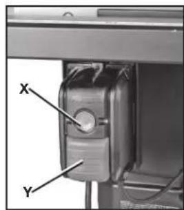
FIG. 19
natural_image
Close-up of a mechanical lock mechanism with a metal bracket and labeled component 'Z' (no text or symbols beyond label)FIG. 20
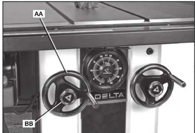
FIG. 21
natural_image
Mechanical assembly with a robotic arm interacting with a rectangular block (no visible text or symbols)FIG. 22
Tighten lock knob (BB) Fig. 21 to keep blade raised to your desired height. Only a small amount of force is required to lock the blade raising mechanism securely. Any added force merely puts unnecessary strain on the locking device.
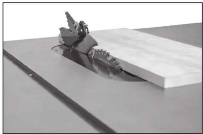
For most applications, it is recommended that you raise the blade 1/8" (3.2 mm) to 1/4" (6.4 mm) above the top surface of the workpiece, as shown in Fig. 22. (NOTE: Guard removed for clarity only.)
NOTE: With hollow-ground blades, raise the blade to its maximum height to provide greater clearance.
WARNING: Lock the blade in position before starting the saw.
TILTING THE BLADE
Tilt the blade to the left using the right handwheel (CC) Fig. 23.
The blade tilting mechanism allows the blade to be tilted up to 45^ to the left.
To tilt the saw blade, loosen the lock knob (DD) Fig. 23 counterclockwise and turn handwheel (CC). A pointer (EE) Fig. 24 indicates the angle of tilt on the scale, marked in 1/2-degree increments.
To lock the saw blade at your desired angle, tighten the lock knob (DD).
THROAT PLATE ADJUSTMENT
The throat plate (FF) Fig. 25 needs to be level to the saw table. If the throat plate is not level with the saw table, adjust the plate using four set screws (GG). Lower or raise set screws as needed to align throat plate level to the saw table.
RIVING KNIFE OPERATION AND ADJUSTMENT
POSITIONING THE RIVING KNIFE
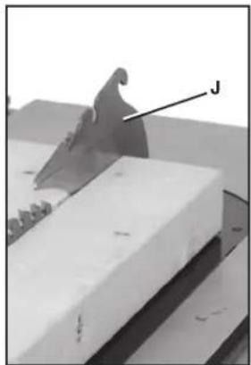
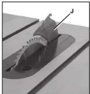
The riving knife (J) Fig. 26 is a flat plate that fits into the cut made by the saw blade and effectively fights kickback by lessening the tendency of the blade to bind in the cut. (NOTE: Safety devices removed for clarity in Fig. 26. Be sure to always use safety devices when possible.)
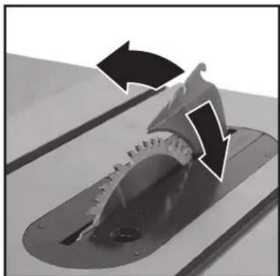
The riving knife (J) Fig. 27 and Fig. 28 can be used in through cuts (where the workpiece is completely cut in two) and non-through cuts. The riving knife can be moved to the high position (Fig. 27) for through cuts and to the low position (Fig. 28) for non-through cuts.
NOTE: When adjusting the riving knife up or down, be sure to pull in a radial motion, as shown in Fig. 28A.
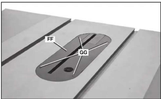
FIG. 25
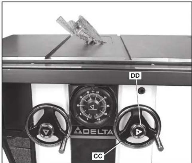
FIG. 23
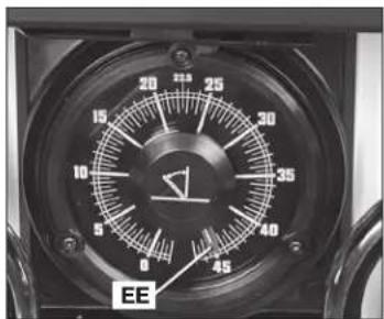
FIG. 24
natural_image
3D rendered mechanical part with a labeled feature 'J' and no visible text or symbolsFIG. 26
natural_image
Close-up of a mechanical component with a labeled part 'J' (no readable text or symbols beyond label)FIG. 27
natural_image
Close-up of a mechanical component with a curved cutaway view and labeled point J (no text or symbols beyond label)FIG. 28
natural_image
Close-up of a mechanical component with directional arrows indicating motion or flow (no text or symbols)FIG. 28A
To adjust the riving knife position, there are two methods:
FRONT-RELEASE (PRIMARY METHOD)
- Pull front riving knife release handle (II) Fig. 29 in front of the saw under the table, just above the gauge.
- While holding handle, pull riving knife up until detent (JJ) Fig. 30 engages for the through-cutting position.
- While holding handle, push riving knife down until detent (KK) Fig. 30 engages for the non-through-cutting position.
- Release handle and pull on riving knife to make sure it is in the locked position.
- Replace throat plate.
RIVING KNIFE RELEASE LEVER (ALTERNATIVE METHOD)
- Remove throat plate (FF) Fig. 25.
- Push riving knife release lever (MM) Fig. 31 away from the blade and pull riving knife up to lower detent (JJ) Fig. 30 for the through-cutting position.
- Push riving knife release lever away from the blade and push riving knife down to upper detent (KK) Fig. 30 for the non-through-cutting position.
- Release lever and pull on riving knife to make sure it is in the locked position.
- Replace throat plate.
⚠ WARNING: Before connecting the table saw to the power source or operating the saw, always inspect the blade guard assembly and riving knife for proper alignment and clearance with saw blade. Check alignment after each change of bevel angle.
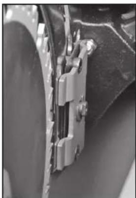
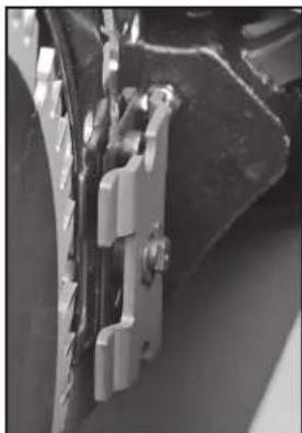
NOTE: DO NOT operate saw if riving knife is not locked in the through-cutting or non through-cutting position. Fig. 31A shows the riving knife clamp locked down properly. Fig. 31B shows the clamp unlocked
When properly aligned, the riving knife will be in line with the blade at both table top level, and at the top of the blade.
Using a straight edge (NN), ensure that the blade (OO) is aligned with the riving knife (J) as shown in Fig. 32. (BE SURE THE STRAIGHT EDGE GOES BETWEEN THE TEETH AND RESTS ON THE BLADE BODY AND THE RIVING KNIFE FOR PROPER ALIGNMENT.)
If the riving knife and blade are out of line, see section, Aligning Riving Knife to Blade.
natural_image
Close-up of a mechanical clamp or bracket assembly (no visible text or symbols)FIG. 31A
natural_image
Close-up of mechanical components with metallic brackets and a black housing (no visible text or symbols)FIG. 31B
natural_image
Close-up of a mechanical control panel with two dials and a delta brand logo (no readable text or symbols beyond branding)FIG. 29
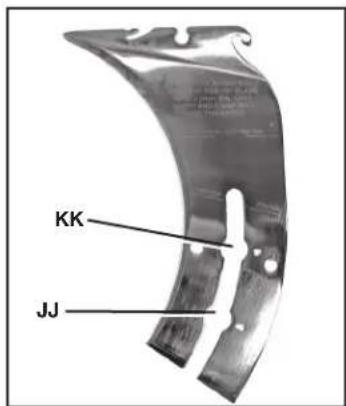
FIG. 30
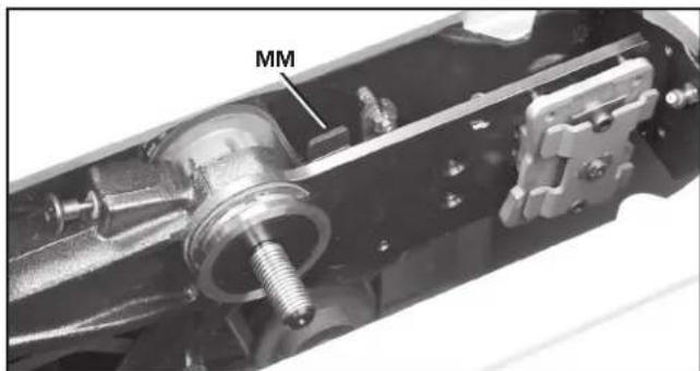
FIG. 31
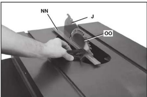
FIG. 32
With power disconnected, operate the blade tilt and height adjustments through the extremes of travel to be sure the blade guard assembly clears the blade in all operations and that the anti-kickback assembly is functioning.
ALIGNING RIVING KNIFE TO BLADE
- Remove the throat plate, blade guard and anti-kickback assemblies.
- Raise the blade to full depth of cut and 0^ bevel angle.
- Raise the riving knife (J) Fig. 33 to the through-cutting or highest position (Fig. 27).
-
Locate the three small set screws (PP) and (QQ) adjacent to the riving knife locking plate (RR). These screws will be used to adjust the riving knife position.
-
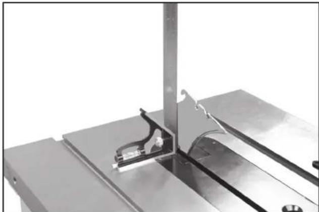
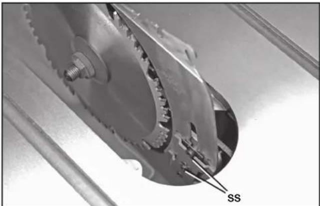
Lay a straight edge on the table against blade body and make sure it extends out along the riving knife, as shown in Fig. 32. The riving knife should just touch the straight edge. If adjustment needed, loosen the two socket head cap screws (SS) Fig. 35.
-
Adjust the set screws (PP) and (QQ) Fig. 33 to move the riving knife in line with the blade according to the position noted in STEP 5. Lay the straight edge on the opposite side of the blade and repeat these adjustments as needed.
NOTE: The two set screws (PP) near the riving knife locking plate (RR) adjust the riving knife as shown from the TOP VIEW (Fig. 36). The set screw (QQ) adjusts the riving knife as shown from the BACK OF TABLE VIEW (Fig. 37).
- Lightly tighten the two socket head cap screws (SS) Fig. 35.
- Place a square flat against the riving knife and verify riving knife is vertical and in-line with the blade. (Fig. 34)
-
If needed, use the set screws to bring the riving knife vertical with the square.
-
Repeat STEPS 5 and 6 to verify position of riving knife.
-
Fully tighten the two socket head cap screws (SS) Fig. 35.
-
Replace throat plate before use.
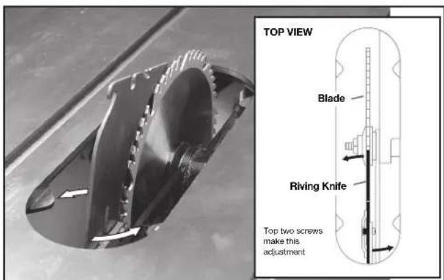
FIG. 36
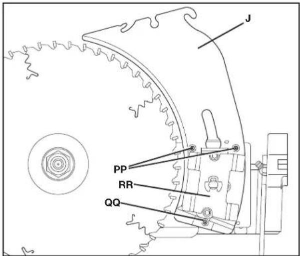
FIG. 33
natural_image
Close-up of a metallic mechanical assembly with a bracket and mounting plate (no visible text or symbols)FIG. 34
natural_image
Close-up of a mechanical gear assembly with labeled component 'SS' (no other text or symbols visible)FIG. 35
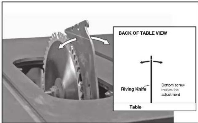
FIG. 37
SELECTING SAW BLADES
⚠ WARNING: Riving knives must be matched to saw blade dimensions in order to function effectively. See Riving Knife Selection.
THIS SAW IS INTENDED FOR USE ONLY WITH SAW BLADES 10" (254 mm) IN DIAMETER. See Fig. 38.
- The saw blade furnished with your new saw is a 10" (254 mm) combination blade, used for cross cutting (across the grain) and ripping (with the grain) through the material. The center hole to fit on the arbor is 5/8" (16 mm) diameter. This blade will produce a good quality cut for most applications.
- There are many types of blades available to do specific and special jobs such as cross cut only, rip only, hollow ground, thin plywood, paneling, etc.
- Use only saw blades designed for maximum safe operating speeds of 4,300 RPM or greater.
- Saw blades should always be kept sharp. It is recommended that you locate a reputable sharpening service to sharpen your blades when needed.
- Never stack blades on top of one another to store. Place material such as cardboard between them to keep the blades from coming in contact with one another, or place them in storage drawer.
⚠ WARNING: Abrasive wheels or blades (including diamond) should not be used on this saw.
RIVING KNIFE SELECTION
⚠ WARNING: To minimize the risk of kickback and to insure proper cutting, the riving knife must be the proper thickness for the blade used.
The riving knife supplied with this table saw is the correct size for the blade supplied with the saw.
If a different blade is used, check the blade body, or plate, thickness and the blade kerf, or cutting, width marked on the blade or on the blade packaging. The riving knife thickness must be greater than the body thickness and less than the kerf width as shown in Fig. 39. If it is not, the riving knife MUST be replaced with one that has the correct thickness.
The riving knife provided with this saw is either 2.7 mm thick or 2.8 mm thick and will be marked in one of two ways:
2.7 MM THICK KNIFE:
0.106" (2.7 mm) THICK RIVING KNIFE. ONLY USE FOR 10" (254 mm) ∅ BLADE WITH 0.114" (2.9 mm) MIN. KERF WIDTH AND 0.098" (2.5 mm) MAX. BODY THICKNESS
2.8 MM THICK KNIFE:
0.110" (2.8 mm) THICK RIVING KNIFE. ONLY USE FOR 10" (254 mm) ∅ BLADE WITH 0.118" (3.0 mm) MIN. KERF WIDTH AND 0.098" (2.5 mm) MAX. BODY THICKNESS
The riving knife available as an accessory marketed by DELTA is marked as follows:
0.087" (2.2 mm) THICK RIVING KNIFE. ONLY USE FOR 10" (254 mm) ∅ BLADE WITH 0.094" (2.4 mm) MIN. KERF WIDTH AND 0.067" (1.75 mm) MAX. BODY THICKNESS. (See Fig. 40)
All DELTA blade body thickness and kerf width information is provided at www.deltaportercable.com.
If a different blade is used and the body thickness and kerf width dimensions are not provided, use the following procedure to determine the correct riving knife thickness:
- Measure the body thickness of the blade.
- Make a shallow cut in scrap material and measure the kerf width.
- Select the riving knife as shown in Fig. 39.
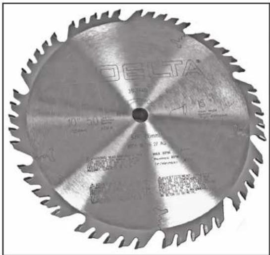
FIG. 38
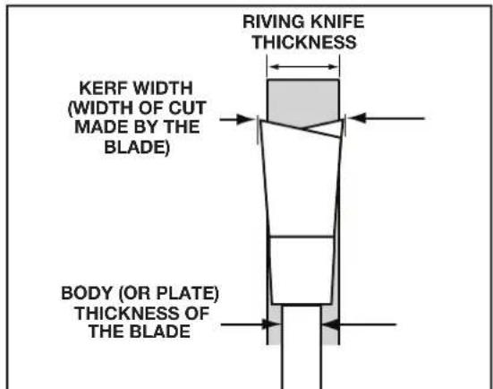
FIG. 39
natural_image
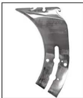
Metallic curved bracket component with mounting holes and a central slot (no visible text or symbols)FIG. 40
natural_image
3D rendered mechanical part with a curved cutaway view showing internal cracks (no text or symbols)FIG. 41
- Slide the riving knife through the shallow cut (Fig. 41) made in step 2 to confirm the correct riving knife has been selected. The riving knife should not bind or drag through the cut.
IMPORTANT: If any dragging or binding of the material is encountered as it reaches the riving knife, turn unit off and disconnect machine from power source. Repeat steps 1–4 to make the proper riving knife selection before attempting another cut.
ADJUSTING 0° AND 45° POSITIVE STOPS
There are built in stops that can position the blade at 0^ and 45^ . If the blade is not properly at 0^ when it is resting on the stop:
- Adjust blade to 0° stop and back it off slightly.
- Loosen the bevel stop nut (UU) slightly using supplied arbor wrench.
- Using blade tilting handwheel (CC), position blade at exactly 0^ .
- Use 6 mm hex wrench inside the bevel stop nut (UU) to turn the stop into place. NOTE: The stop can be rotated either way to position stop against the trunnion.
- Hold the stop in place and tighten the bevel stop nut (UU) with the supplied arbor wrench.
- Verify position by beveling off and then coming back to the stop to check blade position.
NOTE: To adjust the 45° stop, use the other bevel stop nut (TT) and follow the same procedure above.
ADJUSTING BLADE TILT SCALE
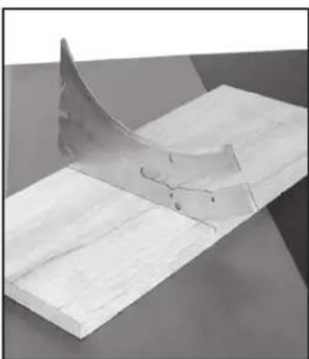
Using a combinaton square, turn blade tilting handwheel until the blade is set perfectly at 45^ . If the blade tilt scale is not pointing to 45^ , follow these steps:
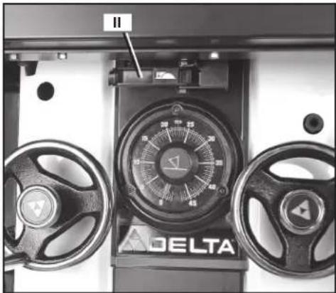
- Remove the magnetic cover (VV) Fig. 43.
- Remove the screw (WW) Fig. 44 using a T20 wrench and remove the center cap (XX).
- Loosen angle indicator screw (YY) Fig. 45.
- Put red pointer on 45^ and tighten screw while holding the back face so the pointer stays on 45^ .
- Replace center cap (XX) Fig. 44. Make sure the rubber O-ring stays seated behind cap.
- Put magnetic cover (VV) Fig. 43 back on.
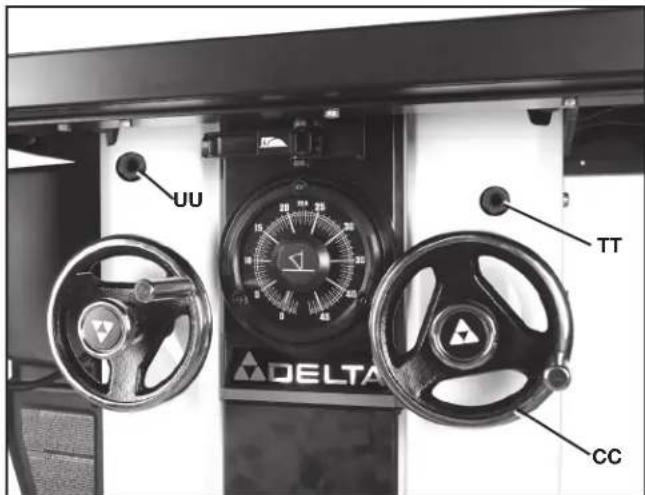
FIG. 42
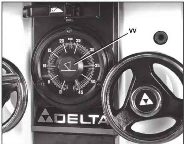
FIG. 43
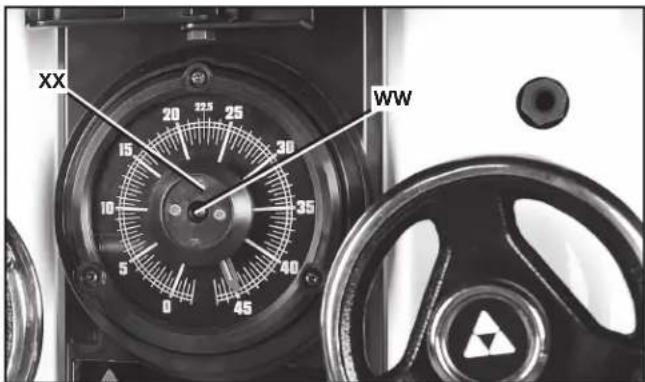
FIG. 44
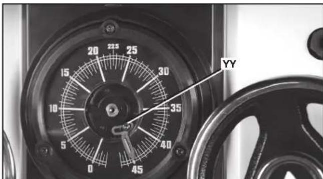
FIG. 45
ADJUSTING MITER SLOT PARALLEL TO BLADE
⚠ WARNING: To reduce the risk of personal injury, turn unit off and disconnect it from power source before installing and removing accessories, before adjusting or when making repairs. An accidental start-up can cause injury.
The saw table was aligned at the factory. For accuracy, check the alignment before beginning operation.
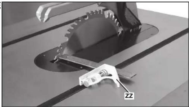
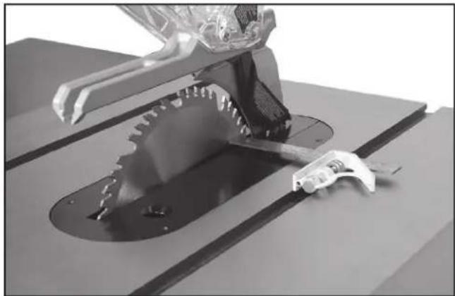
- Place a combination square (ZZ) Fig. 46 on the table with one edge of the square in the miter gauge slot. Adjust the square so that the ruler's edge touches the face of the saw blade at the forward position. Lock the square.
- Rotate the saw blade so that the same spot you used in STEP 1 is in the rear position (Fig. 47) and place ruler edge on the face of the saw at this spot. Both the front and rear measure ments should be the same.
- Then, using a 10 mm hex wrench, loosen the four screws - one shown at (A1) Fig. 48 - that hold the table to the saw cabinet.
- Adjust the front edge of the saw (as shown in Fig. 49). The pivot point on the rear edge of the saw is shown in Fig. 49.
- Move table until the miter slot is parallel with the blade, according to the method described in STEPS 1 and 2.
- Once miter slots are parallel to the blade, finger tighten the four bolts (one shown at (A1) Fig. 48). Check the parallel one last time and fully tighten the bolts.
- Tilt the blade 45° (as shown in Fig. 50), and turn the saw blade by hand. Ensure that the blade does not contact the throat plate.
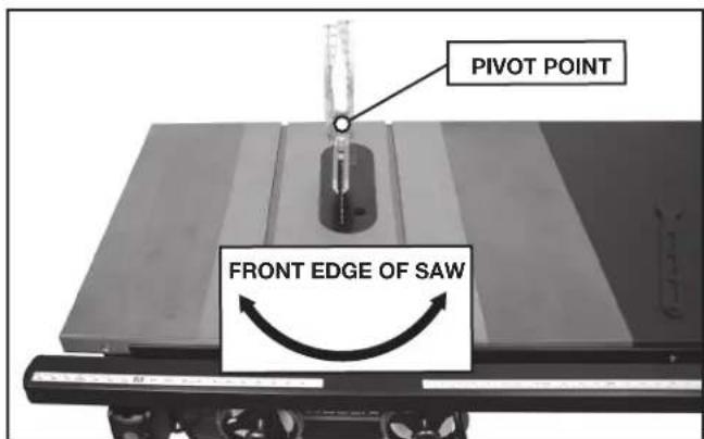
FIG. 49
natural_image
Close-up of a mechanical cutting machine with a gear and a tool, labeled 'ZZ' (no readable text or symbols beyond label)FIG. 46
natural_image
Close-up of a robotic arm cutting a saw blade on a cutting machine (no text or symbols visible)FIG. 47

natural_image
Close-up of a mechanical device with a dial and labeled component A1 (no readable text or symbols beyond label)FIG. 48
natural_image
Close-up of a transparent glass object mounted on a metal base, no visible text or symbolsFIG. 50
TAKING SLACK OUT OF RIVING KNIFE RELEASE CABLE
Over time, the riving knife release cable may develop slack and may not fully open the riving knife release clamp. To remove the slack out of the riving knife release cable:
- Using a 7/16" open end wrench, move nut (B1) Fig. 51 (located underneath the fence in front of saw) away from saw cabinet.
- Using a 7/16" wrench, tighten nut (D1) against the bracket (C1) and nut (B1).
⚠ WARNING: To avoid the risk of injury, do not overtighten the cable. If the cable is too tight, the riving knife will be loose and will not function properly. After adjustments always check that the riving knife is securely clamped in the desired position by firmly pulling up on the knife.
ALIGNING THE RIP FENCE AND TABLE BOARD
See your fence instruction manual for instructions on adjusting the rip fence parallel to the miter gauge slot, as well as instructions for making sure the table board is flat to the extension wings and flat across the whole width of saw, wings and table board.
CHANGING THE SAW BLADE
⚠ WARNING: Use only 10" (254 mm) diameter blades with 5/8" (16 mm) arbor holes, rated at 4,300 rpm or higher.
⚠ WARNING: To reduce the risk of injury, turn unit off and disconnect it from power source before installing and removing accessories, before adjusting or when making repairs. An accidental start-up can cause injury.
- Remove the throat plate (FF) Fig. 52, and raise the saw blade to its maximum height.
- Remove old blade, if needed, by holding red arbor lock button (E1) Fig. 52. Use included arbor wrench to remove the blade retaining nut (F1). Remove old blade.
- Place the new blade on the arbor with the teeth pointing down as the blade rotates toward the front of the saw table.
- Replace the blade retaining nut and throat plate.
MAXIMUM BLADE HEIGHT ADJUSTMENT
The saw is designed so that the top of blade can be raised to a maximum distance of 3-1/8" (79 mm) from the table surface. If the saw is not achieving this height, follow these steps:
- Raise blade to its highest point, then back of slightly.
-
Loosen the blade height stop jam nut (G1) Fig. 53 slightly with a wrench.
-
Set blade height to 3-1/8" (79 mm).
-
Use a hex wrench in the stop bolt to turn the blade height stop into place against the arbor bracket. The stop can be rotated in either direction until it jams against the trunnion.
-
Hold hex wrench in place and tighten the blade height stop jam nut.
-
Lower the blade and re-position against the blade height stop. Verify the height is still 3-1/8" (79 mm).
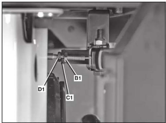
FIG. 51
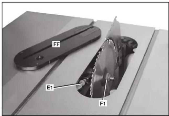
FIG. 52
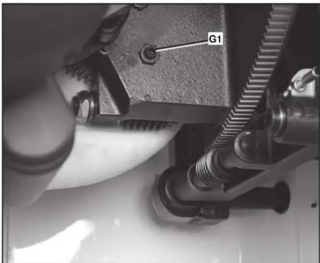
FIG. 53
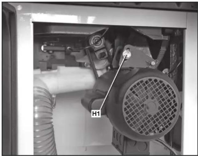
ADJUSTING BELT TENSION
- Open the motor cover.
- Loosen the bolt (H1) Fig. 54A, and carefully let the motor rest on the belts.
- Correct belt tension is indicated with a 1/4" (6.4 mm) deflection in the center span of the pulleys, using light finger pressure.
- When proper tension is achieved, tighten bolt (H1) Fig. 54A.
NOTE: For instructions on replacing the belts see the Maintenance section.
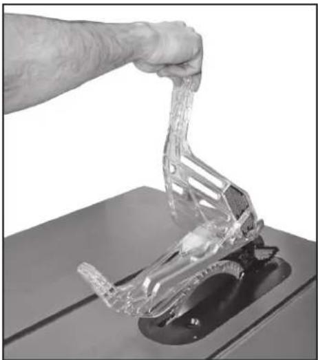
⚠ WARNING: To reduce the risk of injury, turn unit off and disconnect it from power source before installing and removing accessories, before adjusting or when making repairs. An accidental start-up can cause injury.
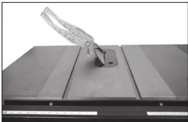
If there is a need to briefly raise the blade guard (for example, to make a measurement) the guard can be parked in a raised position. Lift the guard from the front (as shown in Fig. 54B) and raise guard shield until it snaps into a locked position above the table. One or both guard shields can be raised.
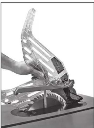
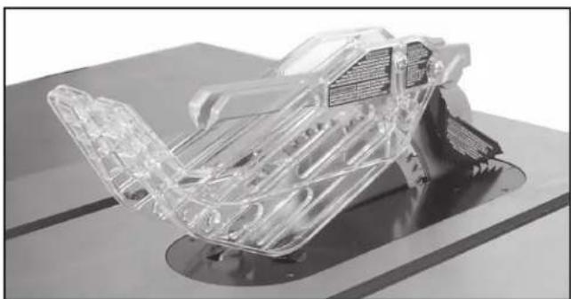
When done making the measurement (Figure 54C), return guard to operating position (Figure 54D).
⚠ WARNING: Keep arms, hands and fingers away from the blade to prevent serious injury.
⚠ WARNING: To reduce the risk of injury, you must use the saw blade guard for all through-cuts.
natural_image
Close-up of a mechanical assembly with a labeled component H1, showing internal components like gears and tubing (no readable text beyond label)FIG. 54A
natural_image
Hand using a tool to lift a transparent plastic clamp on a workbench (no text or symbols visible)FIG. 54B
natural_image
Close-up of a hand gripping a transparent plastic car component (no visible text or symbols)FIG. 54C
natural_image
3D rendered transparent mechanical component with internal structure, mounted on a base (no visible text or symbols)FIG. 54D
MACHINE USE
KICKBACK
Kickback is a dangerous condition! It is caused by the workpiece binding against the blade. The result is that the workpiece can move rapidly in a direction opposite to the feed direction. During kickback, the workpiece could be thrown back at the operator. It can also drag the operator's hand back into the blade if the operator's hand is at the rear of the blade. If kickback occurs, turn the saw "OFF" and verify the proper functioning of the riving knife, anti-kickback assembly and blade guard assembly before resuming work.
WARNING: See Additional Safety Rules for Table Saws and follow all warnings provided regarding kickback.
Common sawing operations include through cuts (like ripping and crosscutting), non-through cuts (like dados and rabbets) plus a few other standard operations. As with all power machines, a certain amount of hazard is involved with the operation and use of the machine. Using the machine with the respect and caution will considerably lessen the possibility of personal injury. However, if normal safety precautions are overlooked or completely ignored, personal injury can result. The following information describes the safe and proper method for performing the most common sawing operations.
⚠ WARNING: Failure to adhere to these common safety rules can greatly increase the likelihood of injury.
- Before using the saw, verify the following each and every time:
A. Always wear proper eye, hearing and respiratory equipment.
B. Blade is tight.
C. Bevel angle and height lock knobs are tight.
D. If ripping, ensure fence lock lever is tight and fence is parallel to the blade.
E. If crosscutting, miter gauge knob is tight.
F. The blade guard /riving knife assemblies are properly attached and the anti-kickback teeth are functioning.
G. Always inspect the guard and riving knife for proper alignment operation and clearance with saw blade.
H. ALWAYS make sure both guards are in the down position in contact with the table before operating.
- To reduce the risk of injury, turn unit off and disconnect machine from power source before installing and removing accessories, before adjusting or changing set-ups or when making repairs. An accidental start-up can cause injury.
- Before connecting the table saw to the power source or operating the saw, always inspect the guard and riving knife for proper operation, alignment and clearance with saw blade. Otherwise, personal injury may result.
- This instruction manual does not provide information regarding the installation of a fence system. A fence system must be installed before use of the saw. Please refer to the fence instruction manual regarding the proper installation, alignment, and operation of the fence system.
- The use of attachments and accessories not recommended by DELTA may result in injury.
- You must use the saw blade guard and riving knife and anti-kickback assemblies for all through cuts. The anti-kickback fingers mount to the riving knife and aid in preventing kickback. The riving knife prevents the wood kerf from closing and binding the blade. Be sure to replace or sharpen the anti-kickback fingers when the points become dull.
- Ripping or crosscutting may cause saw to tip over while operating. If you desire to secure the saw to a stable surface, see instructions in section Securing Saw to a Permanent Location.
- Never use the fence and miter gauge together. This may cause a kickback condition and injure the operator.
- The proper throat plate must be in place at all times to reduce the risk of a thrown workpiece and possible injury.
- If your saw makes an unfamiliar noise or if it vibrates excessively, cease operating immediately until the source has been located and the problem corrected.
- Never perform freehand cutting, plunge cutting, resawing or cove cutting.
MAKING CUTS
There are two basic types of cutting with table saws: ripping and crosscutting. Cutting with the grain is ripping and cutting against the grain is crosscutting. With manmade materials, the distinction is made such that ripping is cutting to a different width and crosscutting describes cutting material across the shorter dimension.
⚠ WARNING: When ripping, always use the fence to provide a guide for the material and guard against a kickback situation.
▲ CAUTION: When crosscutting, always use the miter gauge.
RIPPING
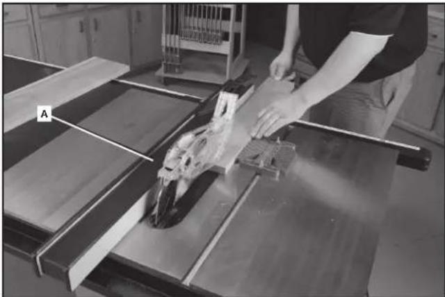
⚠ WARNING: Never touch the free end of the workpiece or a free piece that is cut off, while the power is on and/or the saw blade is rotating. Piece may contact the blade resulting in a thrown workpiece or possible injury.
⚠ WARNING: A rip fence should ALWAYS be used for ripping operations to prevent loss of control and personal injury. NEVER perform a ripping operation freehand. Always lock the fence to the rail.
⚠ WARNING: When bevel ripping and whenever possible, place the fence on the side of the blade so that the blade is tilted away from the fence and hands. Keep hands clear of the blade and use a push stick to feed the workpiece if there is less than 6" (152 mm) between the fence and the blade.
natural_image
Person operating a mechanical tool on a wooden cutting board in a workshop (no visible text or symbols)FIG. 55
⚠ WARNING: Keep hands clear of the blade
⚠ WARNING: Use a push stick to feed the workpiece if there is 2" to 6" (51 to 152 mm) between the fence and the blade. Use a narrow rip auxiliary fence and push block to feed the workpiece if there is 2" (51 mm) or narrower between the fence and the blade.
- Lock the fence down where you want it to be. Remove the miter gauge.
- Raise the blade so it is about 1/8" (3.2 mm) higher than the top of the workpiece.
- Hold the workpiece flat on the table and against the fence (A) Fig. 55. Keep the workpiece about 1" (25 mm) away from the blade.
▲CAUTION: The workpiece must have a straight edge against the fence and must not be warped, twisted or bowed. Keep both hands away from the blade and away from the path of the blade. See proper hand position in Fig. 55.
- Turn the saw on and allow the blade to come up to speed. Both hands can be used in starting the cut. When there is approximately 12" (305 mm) left to be ripped, use only one hand, with your thumb pushing the material, your index and second finger holding the material down and your other fingers hooked over the fence. Always keep your thumb along side your first two fingers and near the fence.
- Keep the workpiece against the table and fence and slowly feed the workpiece rearward all the way through the saw blade. Continue pushing the workpiece until it is clear of the guard and it falls off the rear of the table. Do not overload the motor.
- Never try to pull the workpiece back with the blade turning. Turn the switch off, allow the blade to stop, raise the anti-kickback teeth on each side of the riving knife if necessary and slide the workpiece out.
- When sawing a long piece of material or a panel, always use a work support. A sawhorse, rollers or outfeed assembly provides adequate support for this purpose. The work support must be at the same height as the saw table.
▲CAUTION: Never push or hold onto the free or cut off side of the workpiece.
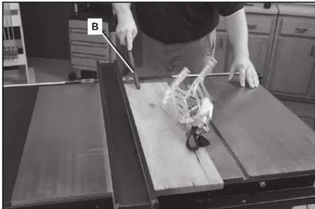
RIPPING SMALL PIECES
It is unsafe to rip small pieces. It is not safe to put your hands close to the blade. Instead, rip a larger piece to obtain the desired piece. When a small width is to be ripped and the hand cannot be safely put between the blade and the rip fence, use one or more push sticks. A pattern is included at the end of this manual to make push sticks. A push stick (B) Fig. 56 is included with this saw. Use the push stick(s) to hold the workpiece against the table and fence, and push the workpiece fully past the blade. See Fig. 56.
natural_image
Person operating a robotic arm on a wooden table, with labeled component B (no visible text or symbols)FIG. 56
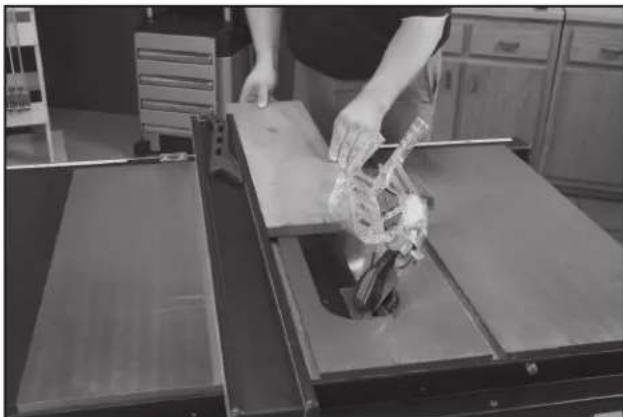
BEVEL RIPPING
Bevel ripping (Fig. 57) is the same as ripping except the bevel angle is set to an angle other than 0^ .
⚠ WARNING: Before connecting the table saw to the power source or operating the saw, always inspect the blade guard assembly and riving knife for proper alignment and clearance with saw blade. Check alignment after each change of bevel angle.
⚠ WARNING: When possible, place the fence on the right side of the blade so that the blade is tilted away from the fence and hands. Keep your hands clear of the blade and use a pushstick to feed the workpiece if there is less than 6" (152 mm) between the fence and the blade.
⚠ WARNING: Use caution when starting the cut to prevent binding of the guard against the workpiece.
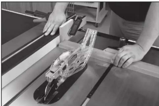
CROSSCUTTING
⚠ WARNING: NEVER touch the free end of the workpiece or a free piece that is cut off, while the power is ON and/or the saw blade is rotating. Piece may contact the blade resulting in a thrown workpiece and possible injury.
⚠ WARNING: To reduce the risk of injury, NEVER use the fence as a guide or length stop when crosscutting.
⚠ WARNING: NEVER use a length stop on the free end of the workpiece when crosscutting. In short, the cut-off piece in any through-sawing (cutting completely through the workpiece) operation must never be confined — it must be allowed to move away from saw blade to prevent contact with blade resulting in a thrown workpiece and possibly injury.
⚠ WARNING: Use caution when starting the cut to prevent binding of the blade guard assembly against the workpiece resulting in damage to saw and possible injury.
△CAUTION: When using a block as a cut-off gauge, the block must be at least 3/4" (19 mm) thick and is very important that the rear end of the block be positioned so the workpiece is clear of the block before it enters the blade to prevent contact with blade resulting in a thrown workpiece and possibly injury.
Cross-cutting is cutting the wood across the grain. It requires the use of the miter gauge to position and guide the work. Before starting the cut, raise the blade so that it is about 1/8" (3.2 mm) higher than the top of the workpiece. Place the work against the miter gauge and advance both the gauge and work toward the saw blade (Fig. 58).
natural_image
Person handling a mechanical device on a workbench in a kitchen setting (no visible text or symbols)FIG. 57
natural_image
Person operating a mechanical assembly with transparent plastic components on a workbench (no visible text or symbols)FIG. 58
You can use the miter gauge in either table slot. Start the cut slowly and hold the work firmly against the miter gauge and the table. Keep both hands on the miter gauge and workpiece. Do not touch the cut-off piece. Feed the workpiece steadily through the blade until the workpiece is completely cut. Shift the workpiece slightly sideways away from the blade, then pull the workpiece and miter guage back to the starting position. Remove the workpiece, then use a push stick to push the cut-off piece past the blade and off the table before beginning the next cut.
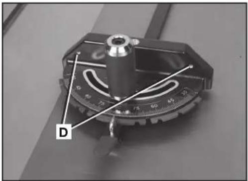
For added safety and convenience, you can fit the miter gauge with an auxiliary wood-facing that should be at least 1" (25 mm) higher than the maximum depth of cut, and should extend out 12" (305 mm) or more to one side or the other depending on which miter gauge slot is being used. This auxiliary wood-facing can be fastened to the front of the miter gauge by using two wood screws through the holes (D) Fig. 59 provided in the miter gauge body and into the wood-facing.
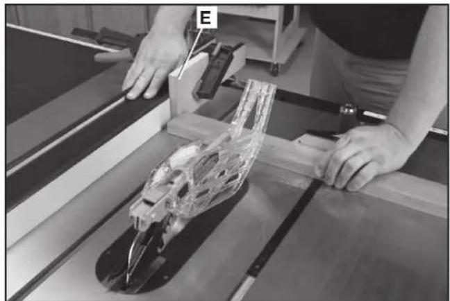
When cross-cutting a number of pieces to the same length, clamp a block of wood (E) Fig. 60 to the fence and use it as a cut-off gauge. The block (E) must be at least 3/4" (19 mm) thick to prevent the cut-off piece from binding between the blade and the fence during removal from the saw table. Always position this block of wood in front of the saw blade. Once the cut-off length is determined, lock the fence and use the miter gauge to feed the work into the cut.
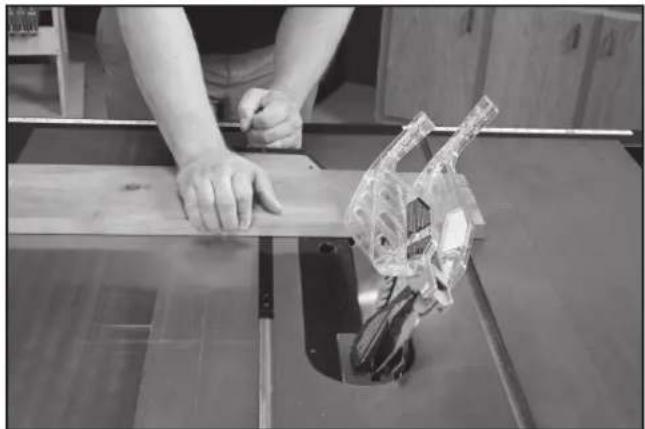
BEVEL CROSSCUTTING
Bevel crosscutting (Fig. 61) is the same as crosscutting except the bevel angle is set to an angle other than 0^ .
⚠ WARNING: Before connecting the table saw to the power source or operating the saw, always inspect the blade guard assembly and riving knife for proper alignment and clearance with saw blade. Check alignment after each change of bevel angle.
⚠ WARNING: When possible, use the right miter gauge slot when bevel crosscutting so that the blade tilts away from the miter gauge and your hands.
⚠ WARNING: Use caution when starting the cut to prevent binding of the guard against the workpiece.
natural_image
Close-up of a mechanical measuring scale with labeled point D (no text or symbols on the scale itself)FIG. 59
natural_image
Person operating a mechanical device with transparent plastic casing, no visible text or symbolsFIG. 60
natural_image
Person using a cutting machine on a wooden workbench, with a transparent plastic component visible (no text or symbols)FIG. 61
MITERING
⚠ WARNING: Miter angles greater than 45^ may force the blade guard assembly into the saw blade causing damage to the blade guard assembly and personal injury. Before starting the motor, test the operation by feeding the workpiece into the blade guard assembly. If the blade guard assembly contacts the blade, place the workpiece under the blade guard assembly, not touching the blade, before starting the motor.
▲CAUTION: Certain workpiece shapes, such as molding may not lift the blade guard assembly properly. With the power off, feed the workpiece slowly into the blade guard area and until the workpiece touches the blade. If the blade guard assembly contacts the blade, place the workpiece under the blade guard assembly, not touching the blade, before starting the motor.
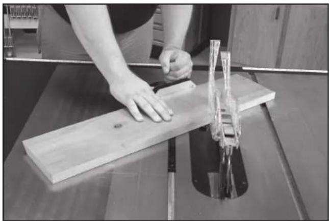
This operation is the same as crosscutting except the miter gauge is locked at an angle other than 0^ . Hold the workpiece FIRMLY against the miter gauge and feed the workpiece slowly into the blade (to prevent the workpiece from moving). See Fig. 62.
The miter gauge is equipped with adjustable index stops at 90°, 75°, 60°, 45° and 30°.
To rotate the miter gauge, loosen handle (G) Fig. 63, push the thumb lever (H) down and move the body of the miter gage (I) to the desired angle.
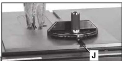
The miter gauge is equipped with a washer on the end of the bar which fits into the T-Slot groove (J) in the table. This allows the miter gauge to be pulled off the front edge of the table without falling. This allows for a longer cut-off capacity in front of the blade.
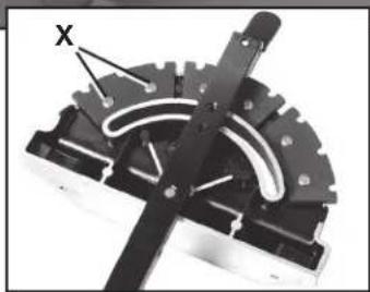
To adjust the stops, loosen screws — two shown at (X) Fig. 63. Move stop to proper position and re-tighten screws (X).
COMPOUND MITERING
This is a combination of bevel crosscutting and mitering. Follow the instructions for both bevel crosscutting and mitering.
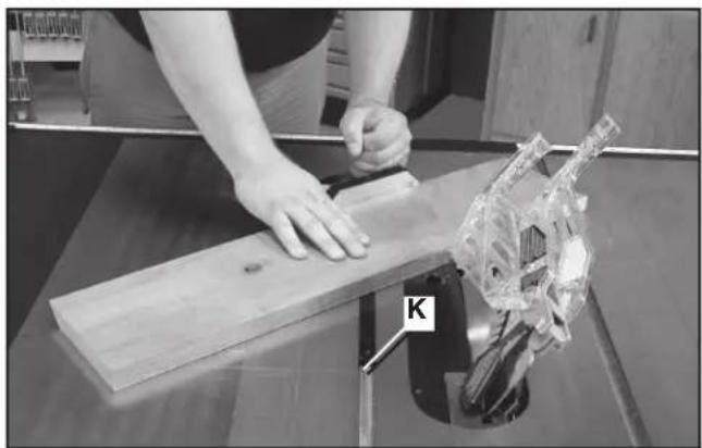
NOTE: Always use the miter slot (K) Fig. 64 which allows the blade to tilt away from the miter gauge and hands.
USING AN ACCESSORY DADO HEAD
WARNING: To reduce the risk of injury, turn unit off and disconnect it from power source before installing and removing accessories, before adjusting or when making repairs. An accidental start-up can cause injury.
⚠ WARNING: Do not attempt to stack dado blades thicker than 1" (25.4 mm) Do not use dado blades larger than 8" (200 mm) in diameter.
WARNING: The riving knife and blade guard assemblies cannot be used when dadoing or molding. It must be removed as described in Riving Knife and Blade Guard Operations section. Use EXTREME care when using the dado without the blade guard assembly and riving knife.
natural_image
Person using a wooden cutting machine to cut a wooden board, no visible text or symbolsFIG. 62
natural_image
Close-up of a mechanical testing setup with a cylindrical component mounted on a base, no visible text or symbols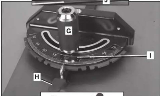
natural_image
Mechanical component with gear and curved internal structure, labeled 'X' (no text or symbols beyond label)FIG. 63
natural_image
Person using a tool on a wooden board next to a transparent mechanical component labeled 'K' (no text or symbols on the object itself)FIG. 64
⚠ WARNING: Use pushsticks, hold-downs, jigs, fixtures or featherboards to help guide and control the workpiece when the guard cannot be used.
▲CAUTION: The accessory dado head set throat plate (L) Fig. 65 must be used in place of the standard throat plate. Be sure the throat plate is level to the table before you proceed.
▲CAUTION: Always check dado blade clearance before plugging in the saw.
⚠ WARNING: To reduce the risk of injury, be sure to place the blade guard assembly and standard throat plate back in position and check adjustments when the dado cuts are complete. Reinstall blade guard assembly, anti-kickback assembly and riving knife.
▲CAUTION: Never use the dado head in a bevel position.
Dadoing is cutting a rabbit or wide groove into the workpiece, as shown in Fig. 66. Most dado head sets are made up of two outside blades and four or five inside chippers, (Fig. 67). Various combinations of blades and chippers are used to cut grooves from 1/8" (3.2 mm) to 1" (25.4 mm) for use in shelving, making joints, tenoning, grooving, etc.
NOTE: The standard outer arbor flange nut assembly (M) Fig. 65 cannot be used with dado blade sets. A special nut (N) is included with the Unisaw to be used in dado applications. Tighten this arbor nut against the dado blade set. Do not discard the outer arbor flange nut. It will be needed when reattaching the standard blade to the arbor.
To arrange a typical dado set:
- The blades and chippers (DELTA 35-7670 is used in this example) are heavily swaged and must be arranged so that the teeth do not hit each other during rotation. The heavy portion of the chippers should fall in the gullets of the outside blades (Fig. 68).
- The blade and chipper profile is shown in Fig. 69. Washers, if needed for fine width adjustment, can be placed anywhere between the outside blades and the chippers. A 1/4" (6.4 mm) groove is cut by using the two outside saws alone.
- Position the teeth of the blade/chipper so that the raker on one is beside the cutting teeth on the other.
- Attach the dado head set to the saw arbor using the arbor nut (N) Fig. 65.
NOTE: If a deep cut is required. Use several successive passes rather than attempting to make it with one pass. Maximum dado width on this saw is 1" (25.4 mm). DO NOT USE WIDER COMBINATIONS.
⚠ WARNING: To reduce the risk of injury, always return and fasten the riving knife and blade guard assemblies to the proper operating position for normal through sawing operations. Also, be sure the standard throat plate is back in position.
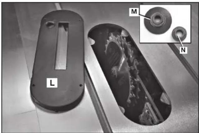
natural_image
Two views of a mechanical component: one with a cutaway view showing internal structure, the other with a magnified inset highlighting a circular feature (no text or symbols present)FIG. 65
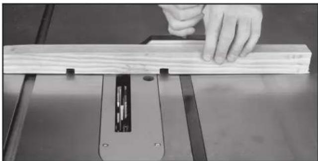
natural_image
Close-up of a hand using a wooden cutting machine to work on a flat surface (no text or symbols visible)FIG. 66
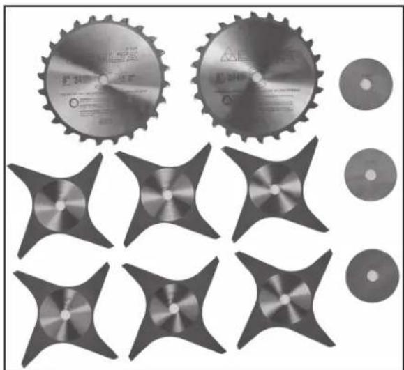
natural_image
Collection of industrial cutting gears and star-shaped components, no visible text or symbolsFIG. 67
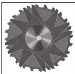
natural_image
Close-up of a metallic gear with visible teeth and central hub (no text or symbols)FIG. 68
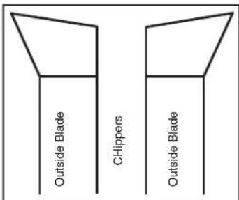
FIG. 69
HOW TO USE A MOLDING CUTTERHEAD
⚠ WARNING: To reduce the risk of injury, turn unit off and disconnect it from power source before installing and removing accessories, before adjusting or when making repairs. An accidental start-up can cause injury.
WARNING: The riving knife and blade guard assemblies cannot be used when dadoing. It must be removed as described in Riving Knife and Blade Guard Operations section. Use EXTREME care when using the dado without the blade guard assembly and riving knife.
⚠ WARNING: Use pushsticks, hold-downs, jigs, fixtures or featherboards to help guide and control the workpiece when the guard cannot be used.
⚠ WARNING: Never use a molding cutterhead (R) Fig. 70 in a bevel position. Always use the proper molding cutterhead throat plate (S).
⚠ WARNING: Never run the stock between the fence and the molding cutterhead. Irregular-shaped wood will cause kickback.
⚠ WARNING: To reduce the risk of injury, always return and fasten the riving knife and blade guard assemblies to the proper operating position for normal through sawing operations. Also, be sure the standard throat plate is back in position.
▲CAUTION: Give special attention to the grain direction. Make all cuts in the same direction as the grain whenever possible.
Molding is cutting a shape on the edge or face of the workpiece with a special molding cutterhead.
The molding head consists of a cutterhead that can be fitted with various shapes of steel cutters (Fig. 71). Each of the three knives in a set is fitted into a groove in the cutterhead and securely clamped with a screw. Keep the knife grooves free of sawdust to allow the cutter to seat properly.
NOTE: The standard outer arbor flange nut assembly (M) Fig. 65 cannot be used with a molding cutterhead. A special nut (N) is included with the Unisaw to be used in these applications. Tighten this arbor nut against the molding cutterhead. Do not discard the outer arbor flange nut. It will be needed when reattaching the standard blade to the arbor.
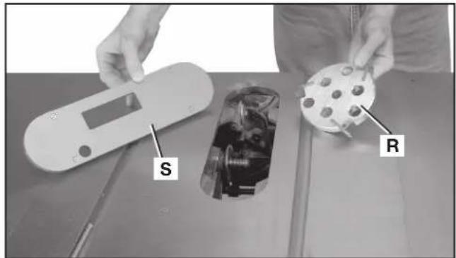
FIG. 70
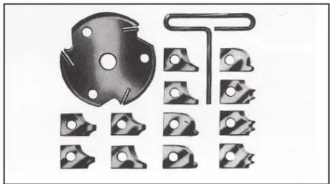
natural_image
Collection of mechanical parts including a circular component and multiple bracketed slots (no text or symbols visible)FIG. 71
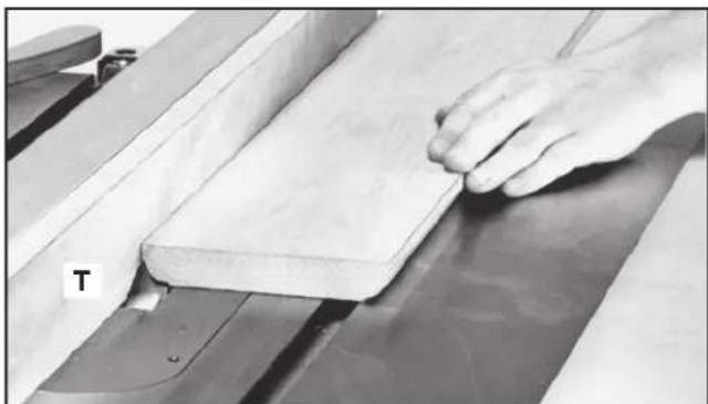
natural_image
Close-up of a hand pressing down on a wooden plank in a machine (no visible text or symbols)FIG. 72
- You can easily attach a molding cutterhead (R) Fig. 70 to the saw arbor. Also, you must use the accessory molding cutterhead throat plate (S) in place of the standard throat plate. Be sure the throat plate is level to the table before you proceed.
- When using the molding cutterhead, add wood-facing (T) to the face of the rip fence (Fig. 72). Attach the wood facing to the fence either with wood screws through holes drilled in the fence, or with two clamps. Stock that is 3/4" (19 mm) thick is suitable for most work, although an occasional job may require 1" (25 mm) facing.
- Position the wood-facing over the cutterhead with the cutterhead below the surface of the table. Turn the saw on and raise the cutterhead. The cutterhead will cut its own groove in the wood-facing. Fig. 71 shows a typical molding operation.
⚠ WARNING: To reduce the risk of injury, always return and fasten the riving knife and blade guard assemblies to the proper operating position for normal through sawing operations. Also, be sure the standard throat plate is back in position
USING AUXILIARY WOOD FACING
Add a wood facing (U) Fig. 73 to one or both sides of the rip fence when you perform special operations (molding cutterhead, etc.). Depending on the fence, attach the wood facing to the fence either with wood screws through holes drilled in the fence, or with two clamps. For most work, 3/4" (19 mm) stock is suitable, although an occasional job may require 1" (25 mm) facing.
CONSTRUCTING AND USING A FEATHERBOARD
Featherboards are used to keep the work in contact with the fence and table (Fig. 74), and help prevent kickback.
Dimensions for making a typical featherboard are shown in Fig. 75. Make your featherboard from a straight piece of wood that is free of knots and cracks. Clamp the featherboard to the fence and table so that the leading edge of the featherboard will support the workpiece until the cut is complete. An 8" (203 mm) high flat board can be clamped to the rip fence and the featherboard can be clamped to the 8" (203 mm) high board.
⚠ WARNING: Use featherboards for all non-through sawing operations where the blade guard and anti-kickback assemblies cannot be used. Always replace the blade guard and anti-kickback assemblies when the non-through sawing operation is complete. Make sure the featherboard presses only on the portion of the workpiece in front of the blade.
If you are using the DELTA accessory featherboard, the one on the table (V) Fig. 76 can be inserted and tightened against the appropriate miter slot. If you use a featherboard on top (not shown) it can be screwed into a board that is clamped to the fence. Be sure all featherboards are tightly fastened before operations.
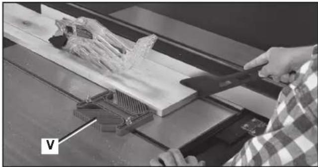
natural_image
Person using a tool on a wooden cutting board with a plastic component, no visible text or symbolsFIG. 76
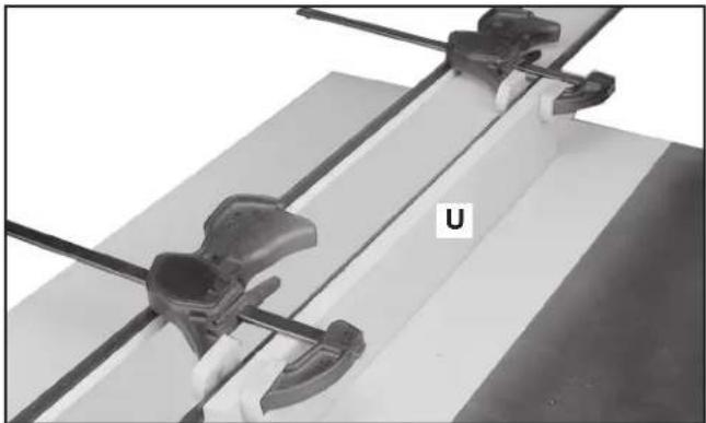
natural_image
Close-up of mechanical clamps and a U-shaped component mounted on a flat surface (no text or symbols visible)FIG. 73

natural_image
Technical line drawing of a wooden clamp or clamping device with a wooden post and two handles (no text or symbols)FIG. 74
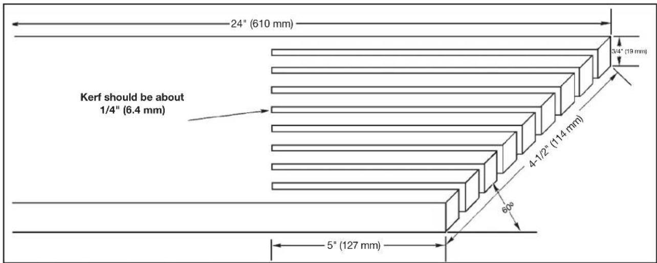
FIG. 75
CONSTRUCTING AND USING A PUSH STICK
In order to operate your table saw safely you must use a push stick (Fig. 78) whenever the size or shape of the workpiece would cause your hands to be within 6" (152 mm) of the saw blade or other cutter (Fig. 79). A push stick is included with this saw.
No special wood is needed to make additional push-sticks as long as it's sturdy and long enough. A length of 10.25" (260 mm) is recommended with a notch that fits against the edge of the workpiece to prevent slipping. It's a good idea to have several push sticks of the same length with different size notches for different workpiece thicknesses.
See the end of the English section for a pattern to make additional push sticks. The shape can vary to suit your own needs as long as it performs its intended function of keeping your hands away from the blade.
Additional Information on table saw safety, including a table saw safety video, is available from the following:
POWER TOOL INSTITUTE
1300 Sumner Avenue
Cleveland, OH 44115-2851
www.powertoolinstitute.com
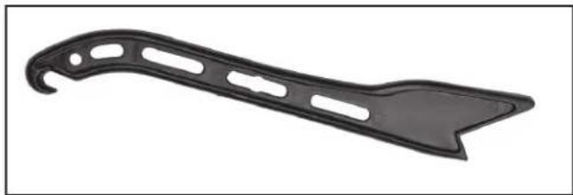
natural_image
Black plastic tool blade with cutouts and a pointed tip (no text or symbols)FIG. 78
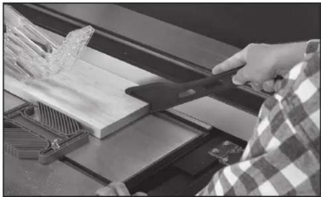
natural_image
Person using a tool to cut wooden planks on a workbench (no visible text or symbols)FIG. 79
TROUBLESHOOTING
For assistance with your machine, visit our website at www.deltaportercable.com for a list of service centers or call the DELTA Machinery help line at 1-800-223-7278 (In Canada call 1-800-463-3582).
MAINTENANCE
⚠ WARNING: To reduce the risk of injury, turn unit off and disconnect it from power source before installing and removing accessories, before adjusting or when making repairs. An accidental start-up can cause injury.
KEEP MACHINE CLEAN
Periodically blow out all air passages with dry compressed air. All plastic parts should be cleaned with a soft damp cloth. NEVER use solvents to clean plastic parts. They could possibly dissolve or otherwise damage the material.
⚠ WARNING: Wear certified safety equipment for eye, hearing and respiratory protection while using compressed air.
FAILURE TO START
Should your machine fail to start, check to make sure the prongs on the cord plug are making good contact in the outlet. Also, check for blown fuses or open circuit breakers in the line.
LUBRICATION & RUST PROTECTION
Apply hardwood flooring paste wax to the machine table, extension table or other work surface weekly. Or use a commercially available protective product designed for this purpose. Follow the manufacturer's instructions for use and safety.
To clean cast iron tables of rust, you will need the following materials: a medium sized scouring pad, a can of spray lubricant and a can of degreaser. Apply the spray lubricant and polish the table surface with the scouring pad. Degrease the table, then apply the protective product as described above.
⚠ WARNING: Wear certified safety equipment for eye, hearing and respiratory protection while using compressed air.
Here are some regular maintenance items to remember for your Unisaw:
RIVING KNIFE CLAMP PLATE (A) Fig. 80: Keep this area free of dust and debris buildup. Blow out area regularly with compressed air.
RIVING KNIFE CLAMP POST (B) Fig. 81: Use lubricant on this area - the post of screw (B) - occasionally to ensure free movement. Place the lubricant on bearing surface of clamp post (B) where it enters the locator block (C) Fig. 80.
NOTE: If the riving knife clamp can't move freely, have the saw serviced by authorized DELTA Machinery service center personnel.
TRUNNION GREASE FITTINGS: Grease the trunnion at two fittings (one shown at (D) Fig. 82) as needed with a lithium-based grease.
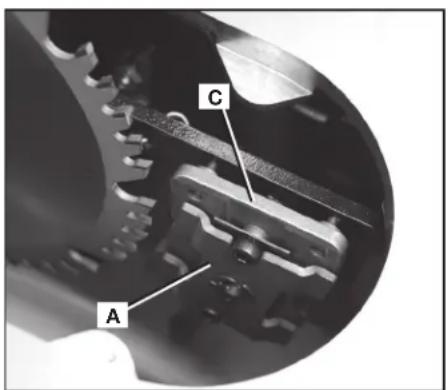
FIG. 80
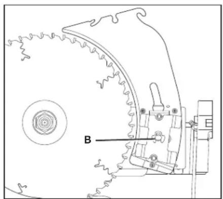
natural_image
Technical line drawing of a mechanical assembly with gear and mounting bracket (no text or symbols)FIG. 81
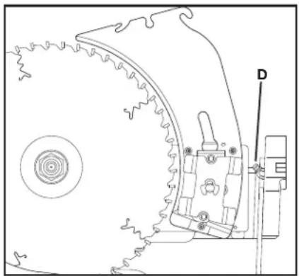
natural_image
Technical line drawing of a mechanical component with gear and mounting bracket (no text or symbols)FIG. 82
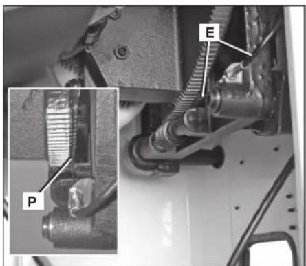
FIG. 83
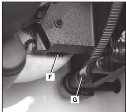
FIG. 84 FIG. 85
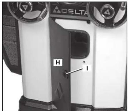
BEVEL INDICATOR CABLE (E) Fig. 83: Keep the cable (E) and mating slot (P) free of dust and debris buildup. Blow out area regularly with compressed air.
AS NEEDED, GREASE THE WORM GEARS (F) and (G) Fig. 84: Keep the worm gears free of dust and debris buildup. Blow out area regularly with compressed air. Use a lithium-based multipurpose grease as needed on these gears. When greasing gears, be careful and do not get any grease on the bevel indicator cable (E) Fig. 83.
CLEAN SAWDUST BUILDUP OUT OF CABINET PERIODICALLY: An access panel (H) Fig. 85 in the front of the saw helps with this. Open the panel — by twisting the knob (I) — and clean out sawdust buildup periodically. NOTE: Debris can also be removed from the Unisaw from below the throat plate, inside the dust port and from behind the motor cover.
⚠ WARNING: To reduce the risk of injury, turn saw off and disconnect power before cleaning or servicing.
REPLACING BELTS
- Open the motor cover (J) Fig. 86.
- Place a piece of wood (K) Fig. 86 between the motor and the saw cabinet.
NOTE: You may need to raise the saw arbor to insert the wood. Lower the saw arbor until the motor contacts the wood. - Loosen the bolt (L) Fig. 87. Lower the saw arbor to remove tension from the belts (M). Tighten the bolt (L).
- Raise the saw arbor slightly and remove the wood (K) Fig. 86.
- Lower the saw arbor to its previous position. Remove the belt (M) Fig. 87 from the pulleys.
- Install the new belt, in the grooves of the arbor pulley (N) Fig. 88, and the motor pulley. (NOT SHOWN.)
- Loosen the bolt (L) Fig. 87, and carefully let the motor rest on the belt.
- Correct belt tension is indicated with a 1/4" (6.4 mm) deflection in the center span of the pulleys, using light finger pressure. Tighten bolt (L) Fig. 87.
- Ensure the cable (O) Fig. 87 is oriented as shown.
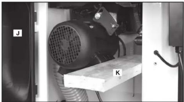
natural_image
Industrial machine setup with labeled components J and K, no visible text or symbols on the equipment itselfFIG. 86
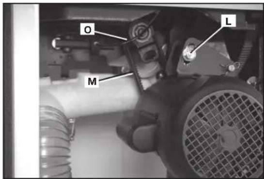
FIG. 87
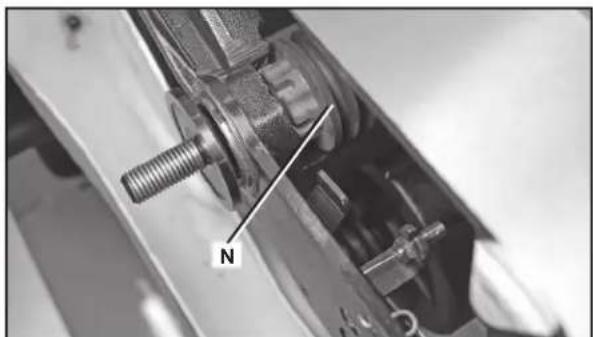
natural_image
Close-up of a mechanical assembly with a threaded bolt and labeled component 'N' (no readable text or symbols beyond the label)FIG. 88
SERVICE
REPLACEMENT PARTS
Use only factory authorized replacement parts. For a parts list or to order parts, visit our website at www.deltaportercableservicenet.com. You can also order parts from your nearest factory-owned branch, Authorized Warranty Service Center or by calling End User Services at (800) 223-7278 to receive personalized support from one of our highly-trained representatives.
FREE WARNING LABEL REPLACEMENT
If your warning labels become illegible or are missing, call 1-800-223-7278 for a free replacement.
WARNING
TO REDUCE THE RISK OF INJURY TURN SAW OFF AND DISCONNECT POWER BEFORE
CLEANING OR SERVICING.
ADVERTENCIA
PARA REDUCIR EL RIESGO DE LESIONES, APAGUE LA SIERRA Y DESCONECTE LA
All quality tools will eventually require servicing and/or replacement of parts. For information about DELTA Machinery, its factory-owned branches, or to locate an Authorized Warranty Service Center, visit our website at www.deltaportercable.com or call our End User Services at (800) 223-7278. All repairs made by our service centers are fully guaranteed against defective material and workmanship. We cannot guarantee repairs made or attempted by others. By calling this number you can also find answers to most frequently asked questions 24 hours/day.
You can also write to us for information at DELTA Machinery, PO Box 2468, Jackson, Tennessee 38302-2468 - Attention: End User Services. Be sure to include all of the information shown on the nameplate of your tool (model number, type, serial number, date code, etc.)
WARNING
TO REDUCE THE RISK OF INJURY USER MUST READ INSTRUCTION MANUAL
BEFORE OPERATING TABLE SAW. FAILURE TO COMPLY WITH THESE N SERIOUS PERSONAL INJURY. ALWAYS WEAR PROPER EYE AND RESPIRATORY THE BLADE GUARD AND RIVING KNIFE FOR EVERY OPERATION FOR WHICH IT CAN THROUGH SAWING. KEEP HANDS OUT OF PATH OF THE LINE OF THE SAW BLADE THEN BEVELING. USE PUSH STICK WHEN REQUIRED. DO NOT PERFORM ANY ALWAYS SUPPORT WORK WITH TABLE AND FENCE OR MITER GAUGE. NEVER SAW BLADE. DO NOT REMOVE JAMMED OR CUT-OFF PIECES UNTIL POWER IS PEPED. DISCONNECT MACHINE FROM POWER SOURCE BEFORE MAKING REPAIRS NOT EXPOSE TO RAIN OR USE IN DAMP LOCATIONS. SECURELY MOUNT SAWING. KNOW HOW TO AVOID RISK OF KICKBACK - SEE MANUAL. USE FENCE WHEN LUGE WHEN CROSSCUTTING. NEVER USE TOGETHER. LOCK BEVEL ADJUSTMENT SECURE TOOL PROPERLY TO PREVENT UNEXPECTED MOVEMENT. WHEN, DO NOT WEAR CLOVES, NECKTIES, JEWELRY, LOOSE CLOTHING OR LONG THE MACHINE WHEN YOU ARE TIRED OR UNDER THE INFLUENCE OF DRUGS, ATION.
ADVERTENCIA
Since accessories other than those offered by DELTA have not been tested with this product, use of such accessories could be hazardous. For safest operation, only DELTA recommended accessories should be used with this product.
A complete line of accessories is available from your DELTA Supplier, PORTER-CABLE • DELTA Factory Service Centers, and DELTA Authorized Service Stations. Please visit our Web Site www.deltaportercable.com for a catalog or for the name of your nearest supplier.
WARRANTY
To register your tool for warranty service visit our website at www.deltaportercable.com.
Five Year Limited New Product Warranty
DELTA will repair or replace, at its expense and at its option, any new DELTA machine, machine part, or machine accessory which in normal use has proven to be defective in workmanship or material, provided that the customer returns the product prepaid to a DELTA factory service center or authorized service station with proof of purchase of the product within five years and provides DELTA with reasonable opportunity to verify the alleged defect by inspection. For all refurbished DELTA product, the warranty period is 180 days. DELTA will not be responsible for any asserted defect which has resulted from normal wear, misuse, abuse or repair or alteration made or specifically authorized by anyone other than an authorized DELTA service facility or representative. Under no circumstances will DELTA be liable for incidental or consequential damages resulting from defective products. Some states do not allow the exclusion or limitation of incidental or consequential damages, so the above limitation or exclusion may not apply to you. This warranty is DELTA's sole warranty and sets forth the customer's exclusive remedy, with respect to defective products; all other warranties, express or implied, whether of merchantability, fitness for purpose, or otherwise, are expressly disclaimed by DELTA. For further detail of warranty coverage and warranty repair information, visit www.deltaportercable.com or call (888) 848-5175. This warranty gives you specific legal rights and you may have other rights which vary in certain states or provinces.
LATIN AMERICA: This warranty does not apply to products sold in Latin America. For products sold in Latin America, see country specific warranty information contained in the packaging, call the local company or see website for warranty information.
CONSTRUCTING A PUSH STICK
⚠ WARNING: When ripping work less than 6" (152 mm) wide, use a push stick to complete the feed. You can make one from scrap material by using this pattern.
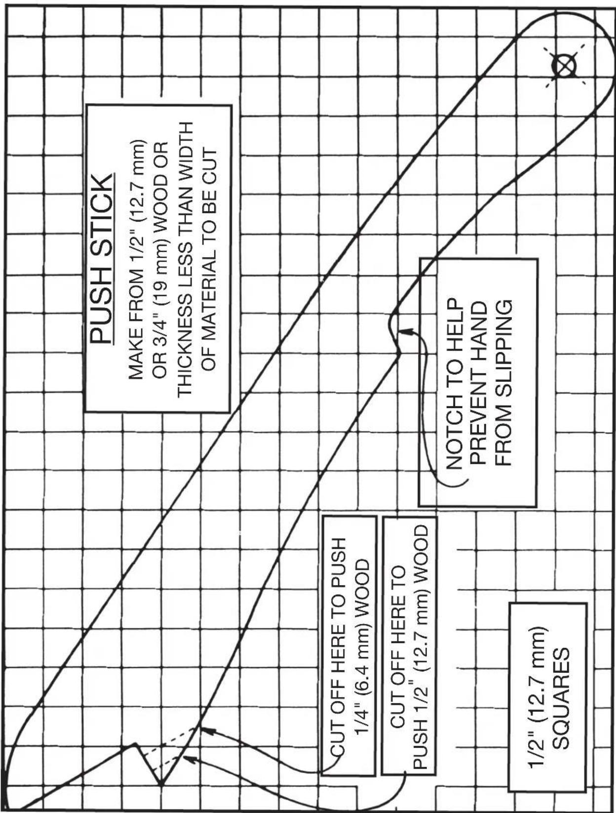
LES INSTRUCTIONS IMPORTANTES DE SURETE
• Power Tool Institute, 1300 Sumner Avenue, Cleveland, OH 44115-2851 ou en ligne www.powertoolinstitute.com
• National Safety Council, 1121 Spring Lake Drive, Itasca, IL 60143-3201
- American National Standards Institute, 25 West 43rd Street, 4 floor, New York, NY 10036 www.ansi.org - ANSI 01.1 Safety Requirements for Woodworking Machines
• U.S. Department of Labor: www.osha.gov
natural_image
Two gray rectangular blocks with a diagonal line and the number 2 above them, no text or symbols present.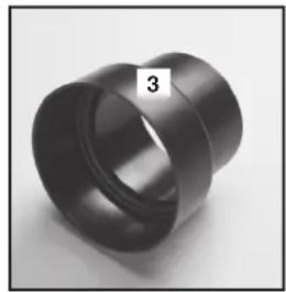
natural_image
Close-up of a black cylindrical mechanical part with a numbered label '3' on the side (no other text or symbols visible)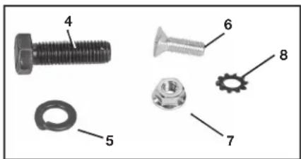

natural_image
Black tool with handle and labeled number 17 (no text or symbols on the object itself)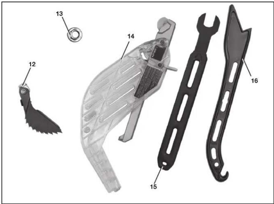
DÉSEMBALLAGE ET NETTOYAGE
natural_image
Close-up of a mechanical control panel with two rotary knobs and a dial, labeled 'C' (no readable text or symbols beyond branding)FIG. 2
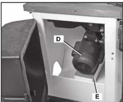
FIG. 3
ASSEMBLAGE
natural_image
Interior view of a ceiling-mounted industrial equipment unit with a V-shaped metal frame and labeled component 'H' (no readable text or symbols beyond label)FIG. 7
INTERRUPTEUR
natural_image
Close-up of a mechanical component with a circular recessed part and a central hole, no visible text or symbols.FIG. 9
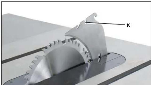
natural_image
Close-up of a metallic gear component with a labeled arrow 'K' pointing to it (no other text or symbols visible)FIG. 10
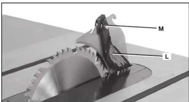
FIG. 11
ENSEMBLE PROTÈGE-LAME
natural_image
Close-up of a mechanical measuring tool with a central knob and scale, no visible text or symbolsFIG. 16
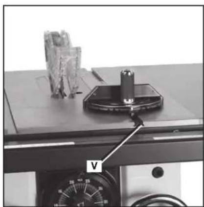
natural_image
Laboratory setup with a metal clamp and labeled component V, no visible text or symbols on the main subject.FIG. 17
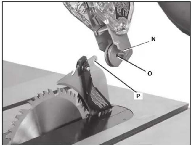
FIG. 12
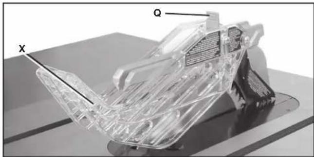
natural_image
3D rendered mechanical component with transparent internal structure and labeled points X and Q (no text or symbols beyond labels)FIG. 13
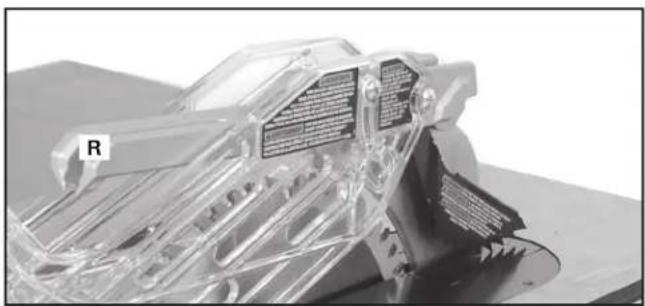
natural_image
3D cutaway view of a mechanical component with transparent internal structure and labeled 'R' (no readable text or symbols)FIG. 14
RANGEMENT DU GUIDE D'ONGLET
natural_image
Close-up of a hand holding a SDELTA lock mechanism against a metal door (no visible text or symbols)FIG. 17A
natural_image
Close-up of a black plastic mechanical component with a labeled part 'W' and an inset image showing a cylindrical ring labeled 'G1' (no text or symbols on the main subject)FIG. 18
FONCTIONNEMENT
L'OPERATION CONTROLE DE LE ET LES AJUSTEMENT
AVERTISSEMENT :
natural_image
Close-up of a mechanical lock mechanism with a labeled component 'Z' (no text or symbols beyond the label)FIG. 20
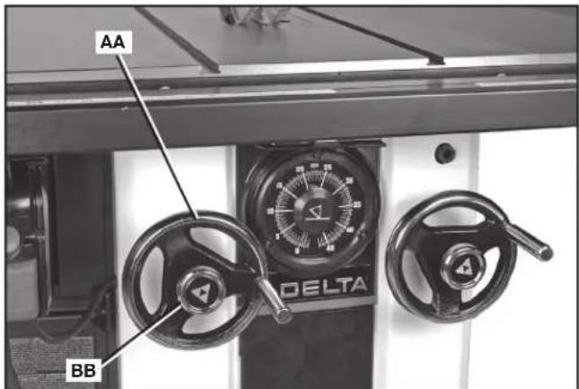
FIG. 21
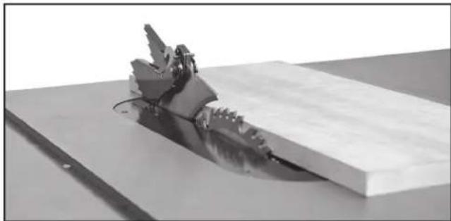
natural_image
Mechanical assembly with a robotic arm and base plate (no visible text or symbols)FIG. 22
ATTENTION:
natural_image
3D rendered object resembling a cake or cheese block with a shadower and label 'J' pointing to it (no readable text or symbols beyond the label)FIG. 26
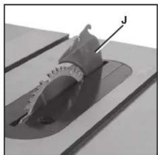
natural_image
Close-up of a mechanical component with a labeled arrow pointing to a feature, no visible text or symbols.FIG. 27
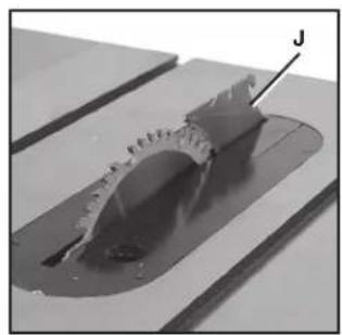
natural_image
Close-up of a mechanical component with a labeled arrow pointing to a feature, no visible text or symbols.FIG. 28
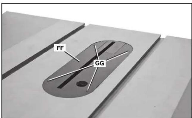
FIG. 25
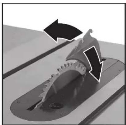
natural_image
Close-up of a mechanical component with directional arrows indicating motion or force (no text or symbols)FIG. 28A
natural_image
Close-up of a mechanical device with dual rotary gauges and control knobs (no visible text or symbols)FIG. 29
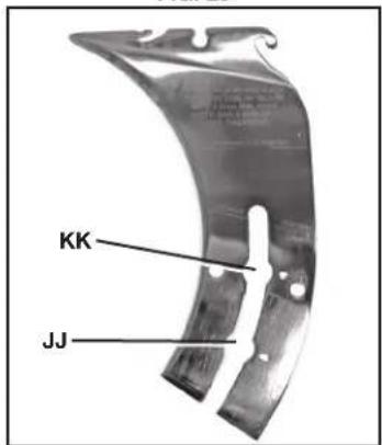
FIG. 30
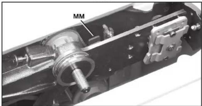
FIG. 31
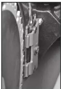
natural_image
Close-up of a mechanical component with metallic parts and mounting brackets (no visible text or symbols)FIG. 31A
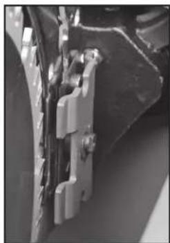
natural_image
Close-up of mechanical components with no visible text or symbolsFIG. 31B

FIG. 32
ALIGNEMENT DU COUTEAU SÉPARATEUR SUR LA LAME
FIG. 33
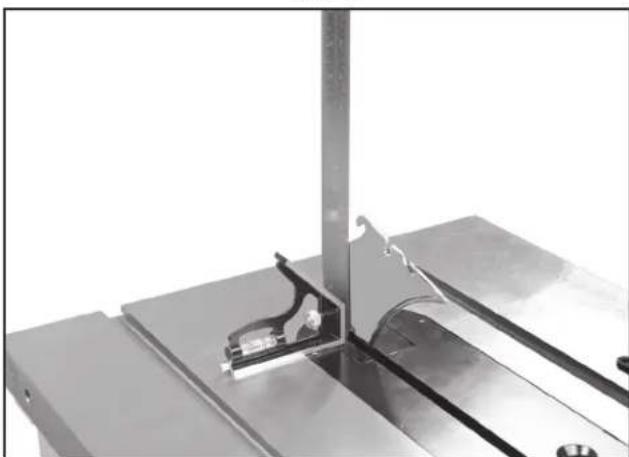
natural_image
Close-up of a metallic mechanical assembly with a vertical support and internal components (no visible text or symbols)FIG. 34
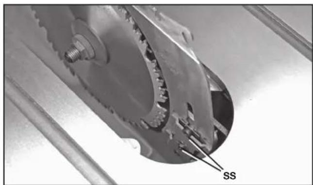
natural_image
Close-up of a mechanical gear assembly with labeled component 'SS' (no other text or symbols visible)FIG. 35
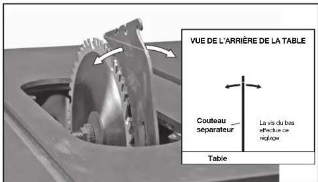
natural_image
Metallic curved bracket with two slots and mounting holes (no visible text or symbols)FIG. 40
COUTEAU SÉPARATEUR DE 2,7 mm (0.106 po) D'ÉPAISSEUR:
« COUTEAU SÉPARATEUR DE 2,7 mm (0.106 po) D'ÉPAISSEUR. CONÇU UNIQUEMENT POUR UNE LAME DE 254 mm (10 po) AVEC UNE LARGEUR DE TRAIT MIN. DE 2,9 mm (0.114 po) ET UNE ÉPAISSEUR DE CORPS MAX. DE 2,5 mm (0.098 po). »
COUTEAU SÉPARATEUR DE 2,8 mm (0.110 po) D'ÉPAISSEUR:
« COUTEAU SÉPARATEUR DE 2,8 mm (0.110 po) D'ÉPAISSEUR. CONÇU UNIQUEMENT POUR UNE LAME DE 254 mm (10 po) AVEC UNE LARGEUR DE TRAIT MIN. DE 3.0 mm (0.118 po) ET UNE ÉPAISSEUR DE CORPS MAX. DE 2.5 mm (0.098 po). »
natural_image
3D rendering of a translucent sheet metal with a curved cutout, placed on a flat surface (no text or symbols visible)FIG. 41
natural_image
Close-up of a mechanical device with gear and tools, no visible text or symbolsFIG. 46
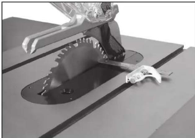
natural_image
3D rendered mechanical component with teeth and a tool, no visible text or symbolsFIG. 47
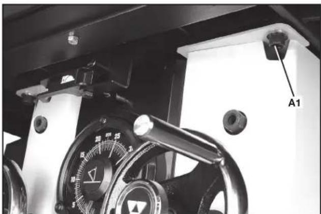
natural_image
Close-up of a mechanical device with a dial and labeled component A1 (no readable text or symbols beyond label)FIG. 48
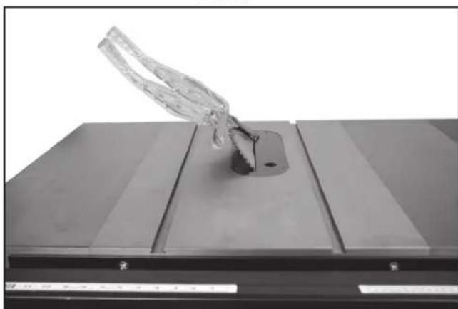
natural_image
Close-up of a transparent glass object mounted on a dark rectangular base, with no visible text or symbols.FIG. 50
TENSION DU CÂBLE DE DÉGAGEMENT DU COUTEAU SÉPARATEUR
natural_image
Interior view of a mechanical assembly with visible components and a labeled section H1 (no text or symbols beyond label)FIG. 54A
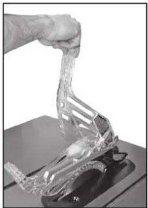
natural_image
Close-up of a hand holding a transparent plastic object over a dark base (no text or symbols visible)FIG. 54B
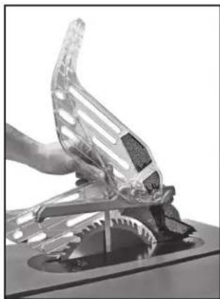
natural_image
Close-up of a hand holding a transparent plastic mechanical component, possibly a tool or device (no visible text or symbols)FIG. 54C
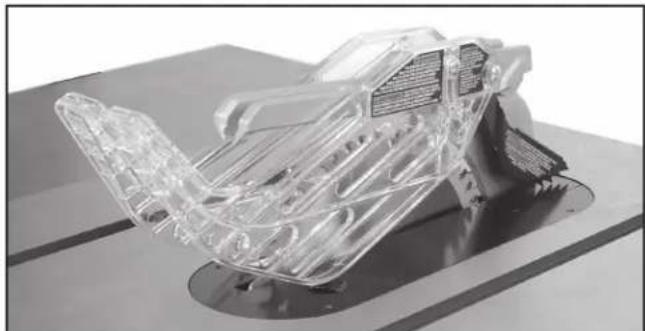
natural_image
3D rendered transparent mechanical component with internal wiring, mounted on a base (no visible text or symbols)FIG. 54D
UTILISATION DE LA MACHINE
REBONDS
natural_image
Person operating a mechanical device on a workbench, no visible text or symbolsFIG. 55
natural_image
Person operating a robotic arm on a workbench, with tools and equipment visible (no text or symbols)FIG. 56
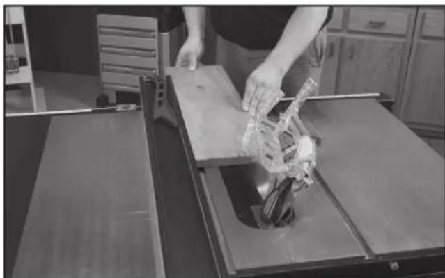
natural_image
Person operating a robotic arm on a workbench in a kitchen setting (no visible text or symbols)FIG. 57
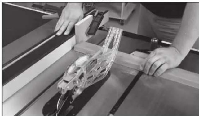
natural_image
Person assembling a transparent plastic car body on a wooden frame (no visible text or symbols)FIG. 58
natural_image
Person operating a mechanical assembly with a transparent plastic component, no visible text or symbolsFIG. 60
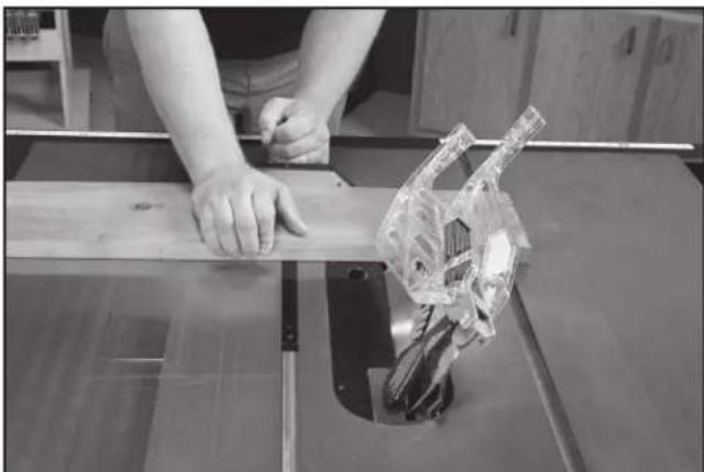
natural_image
Person using a cutting machine on a wooden workbench, with a transparent mechanical component visible (no text or symbols)FIG. 61
ONGLET
natural_image
Person using a tool to cut or spread wood on a workbench, no visible text or symbolsFIG. 62
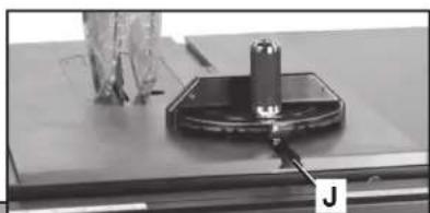
natural_image
Close-up of a mechanical component with a cylindrical part mounted on a base, labeled 'J' (no visible text or symbols on the object itself)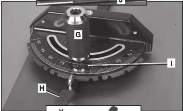
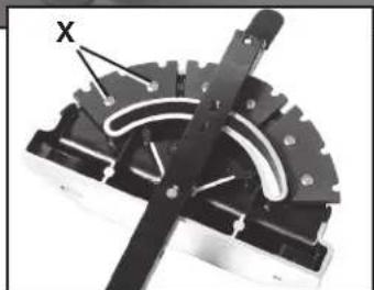
natural_image
Mechanical component with gear and central pin (no visible text or symbols)FIG. 63
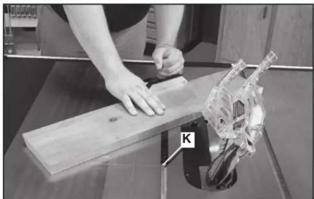
natural_image
Person using a wooden board to work on a mechanical fixture, with a clear plastic component labeled 'K' visible (no text or symbols on the object itself)FIG. 64
natural_image
Two metallic mechanical components labeled L and M, with a close-up inset showing internal components (no text or symbols beyond labels)FIG. 65
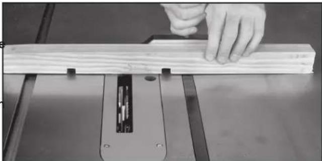
natural_image
Close-up of a hand using a wooden cutting machine to work on a wooden plank (no text or symbols visible)FIG. 66
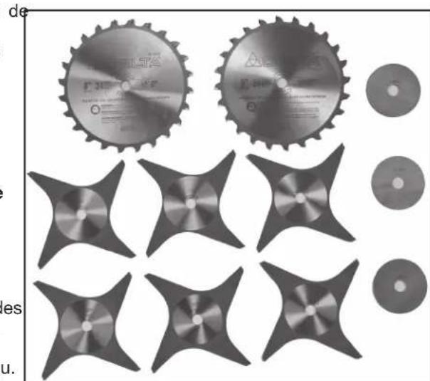
natural_image
Collection of mechanical components including gears, blades, and discs (no text or symbols visible)FIG. 67
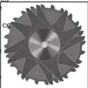
natural_image
Close-up of a metallic gear with symmetrical blades and central hub (no text or symbols visible)FIG. 68
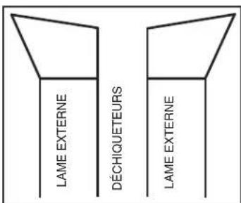
FIG. 69
natural_image
Collection of mechanical parts including a circular component and multiple bracketed slots (no text or symbols visible)FIG. 71
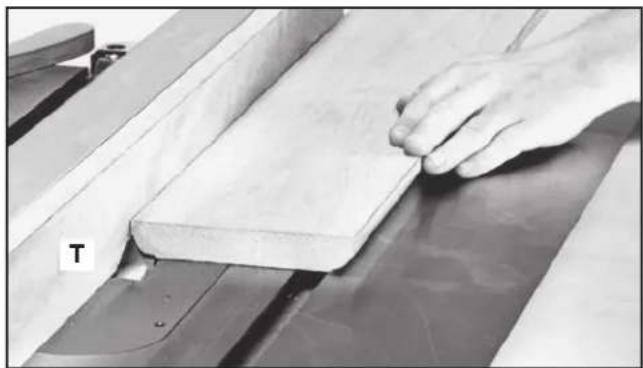
natural_image
Close-up of a hand pressing down on a wooden plank on a machine (no text or symbols visible)FIG. 72
natural_image
Person using a cutting tool on a workbench with a skull model, no visible text or symbolsFIG. 76
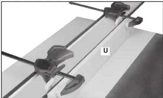
natural_image
Close-up of mechanical clamping components mounted on a flat surface, no visible text or symbolsFIG. 73
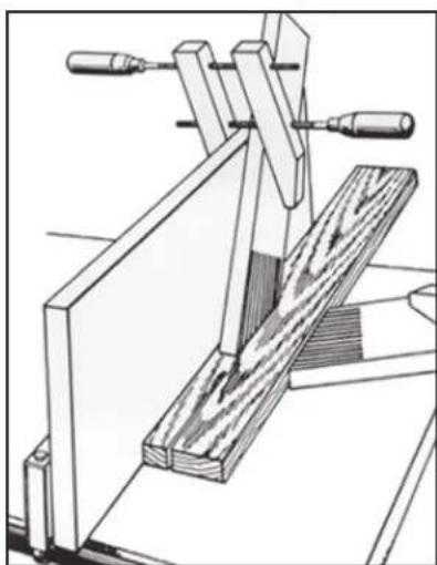
natural_image
Technical line drawing of a wooden clamp or clamping device with two handles and a wooden block (no text or symbols)FIG. 74
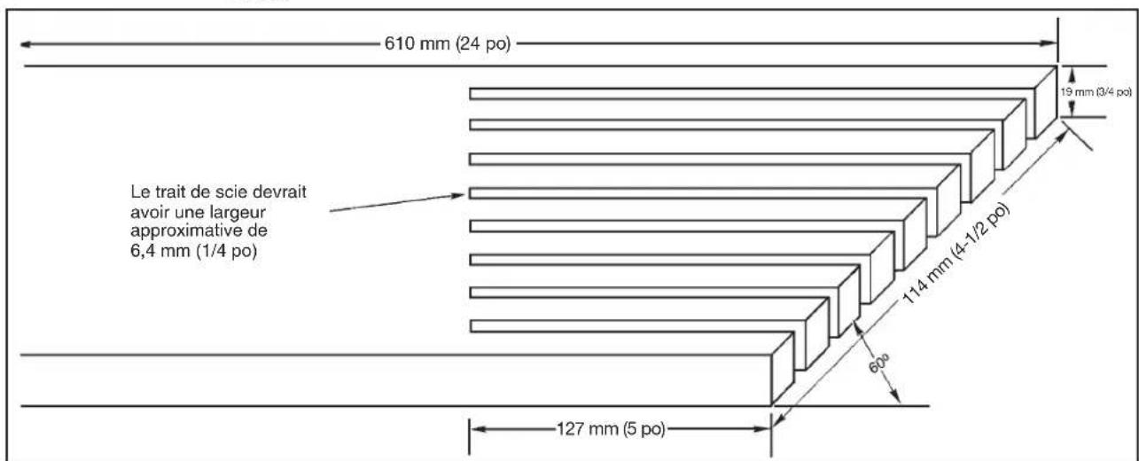
other
| Segment | Dimension (mm) | Slope (po) | |---------|----------------|------------| | Top Segment | 610 | 24 | | Middle Segment | 19 | 3/4 | | Bottom Segment | 114 | 4-1/2 | | Bottom Segment | 60 | - | | Bottom Segment | 127 | 5 | Le Trait de scie devrait avoir une largeur approximative de 6,4 mm (1/4 po)FIG. 75
FABRICATION ET UTILISATION D'UN POUSSOIR
Power tool institute
1300 Sumner Avenue
Cleveland, OH 44115-2851 ÉTATS-UNIS
www.powertoolinstitute.com
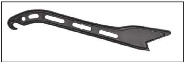
natural_image
Black plastic object with curved handle and cutouts, isolated on white background (no text or symbols)FIG. 78
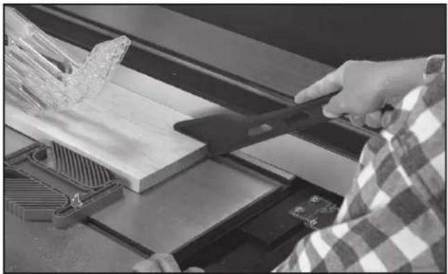
natural_image
Person using a tool to cut wood or metal components on a machine (no visible text or symbols)FIG. 79
DEPANNAGE
DÉMARRAGE IMPOSSIBLE
natural_image
Technical line drawing of a mechanical assembly with gear and base components (no text or symbols)FIG. 81
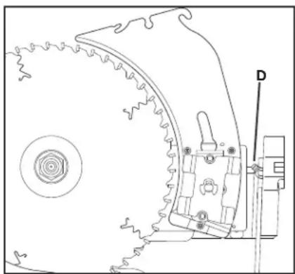
natural_image
Technical line drawing of a mechanical component with gear and mounting bracket (no text or symbols)FIG. 82
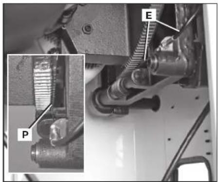
natural_image
Mechanical assembly diagram showing a component with labeled parts P and E, no readable text or symbols present.FIG. 83
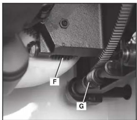
FIG. 84 FIG. 85
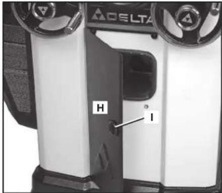
natural_image
Interior view of a mechanical assembly with labeled components J and K (no readable text or symbols beyond labels)FIG. 86
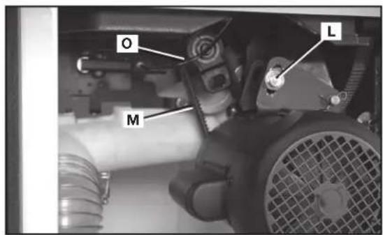
FIG. 87
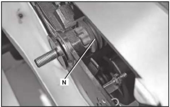
natural_image
Close-up mechanical assembly showing a threaded bolt and housing component (no visible text or symbols)FIG. 88
SERVICE
PIÈCES DE RECHANGE
CLEANING OR SERVICING.
ADVERTENCIA
PARA REDUCIR EL RIESGO DE LESIONES, APAGUE LA SIERRA Y DESCONECTE LA
• Power Tool Institute, 1300 Sumner Avenue, Cleveland, OH 44115-2851 o en línea www.powertoolinstitute.com
• National Safety Council, 1121 Spring Lake Drive, Itasca, IL 60143-3201
- American National Standards Institute, 25 West 43rd Street, 4 floor, New York, NY 10036 www.ansi.org - ANSI 01.1 Safety Requirements for Woodworking Machines
• U.S. Department of Labor: www.osha.gov
natural_image
Two gray rectangular blocks with a labeled point '2' between them, no text or symbols present.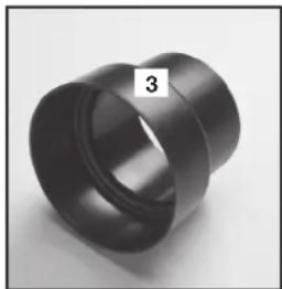
natural_image
Close-up of a black cylindrical mechanical part with a flanged end, labeled '3' in the corner (no other text or symbols visible)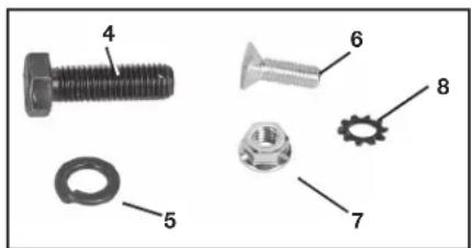
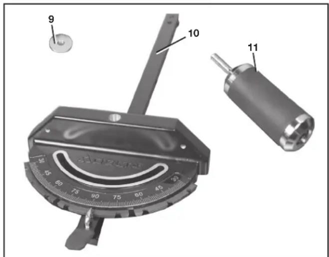
natural_image
Black mechanical tool with handle and labeled part (17), no visible text or symbols on the object itself
DESEMPAQUETADO Y LIMPIEZA
natural_image
Close-up of a Delta air conditioner unit with two rotary knobs and a dial (no visible text or symbols)FIG. 2
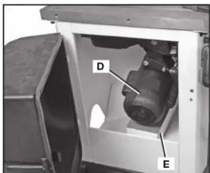
FIG. 3
ENSAMBLAJE
ADVERTENCIA:
natural_image
Interior view of a ceiling-mounted industrial or electrical cabinet with a V-shaped metal bracket and labeled point H (no text or symbols beyond the label)FIG. 7
INTERRUPTOR
natural_image
Mechanical assembly with numbered components and a close-up inset showing two parts (6 and 7) without any readable text or symbols.FIG. 8
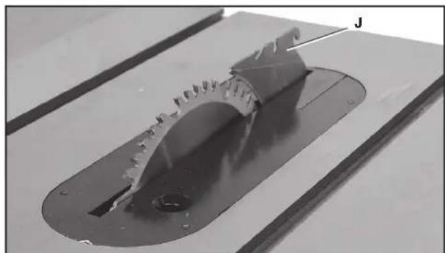
natural_image
Close-up of a mechanical component with a recessed flange and central hole, mounted on a workbench (no visible text or symbols)FIG. 9

natural_image
Close-up of a mechanical gear assembly with a labeled component 'K' (no other text or symbols visible)FIG. 10
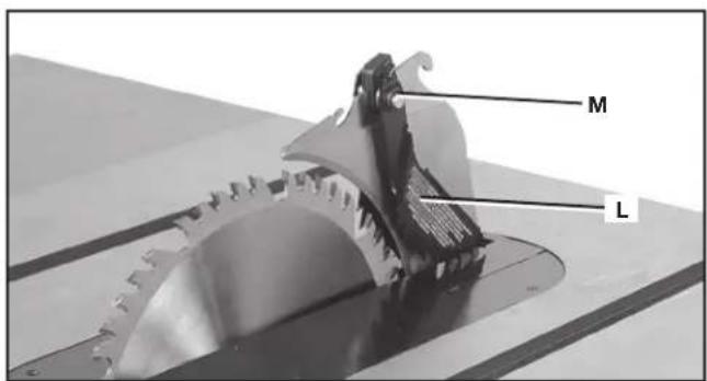
FIG. 11
ENSAMBLAJE DEL PROTECTOR DE LA HOJA
natural_image
Close-up of a mechanical measuring tool with a central knob and scale, no visible text or symbolsFIG. 16
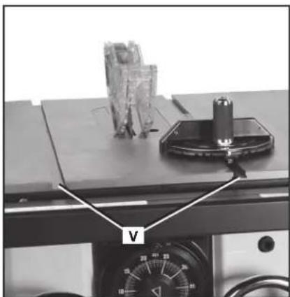
natural_image
Close-up of a mechanical device with labeled component 'V' and control panel (no readable text or symbols beyond label)FIG. 17

FIG. 12
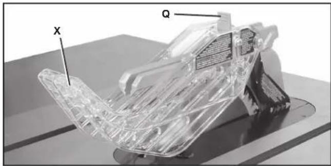
natural_image
3D rendered mechanical component with transparent plastic structure and labeled axes X and Q (no text or symbols beyond labels)FIG. 13
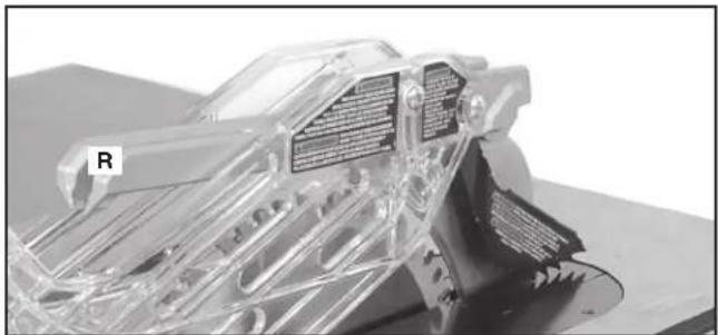
natural_image
3D cutaway view of a mechanical assembly with transparent internal components and labeled part 'R' (no readable text or symbols beyond label)FIG. 14
ALMACENAMIENTO DEL CALIBRADOR DE INGLETE
natural_image
Close-up of a hand holding a belt switch mechanism, no visible text or symbolsFIG. 17A
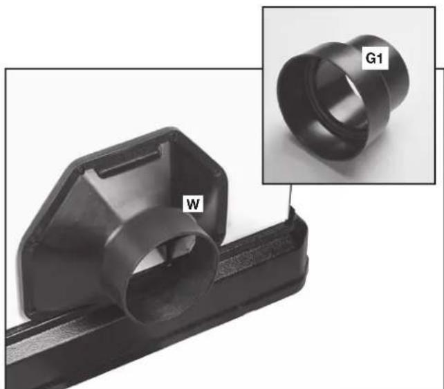
natural_image
Close-up of a black plastic mechanical component with a labeled part 'W' and an inset image showing a cylindrical ring labeled 'G1' (no text or symbols on the main subject)FIG. 18
OPERACIÓN
natural_image
Close-up of a mechanical lock component with a metal bracket and labeled part 'Z' (no text or symbols beyond label)FIG. 20
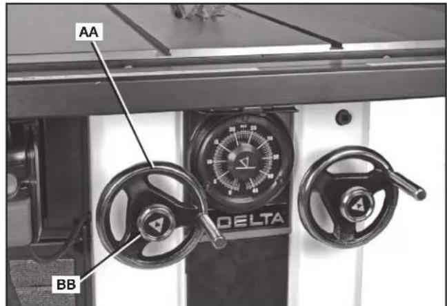
FIG. 21
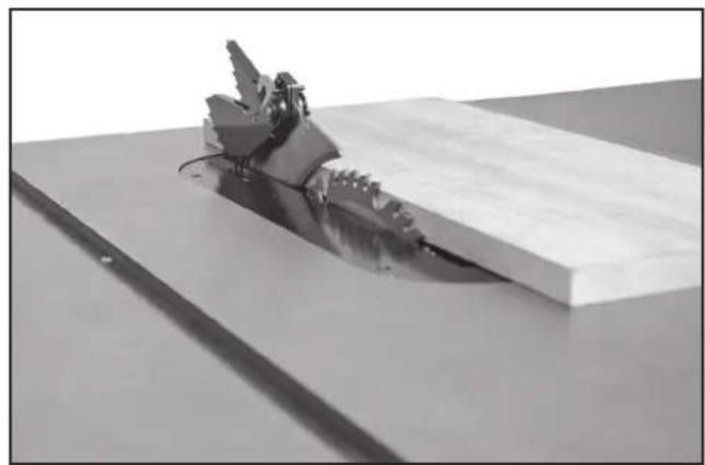
natural_image
Mechanical assembly with a metallic tool inserted into a rectangular block on a flat surface (no text or symbols visible)FIG. 22
CÓMO LEVANTAR Y BAJAR LA HOJA
CÓMO INCLINAR LA HOJA
natural_image
3D rendered mechanical part with a labeled feature 'J' and a curved blade-like structure (no text or symbols beyond label)FIG. 26
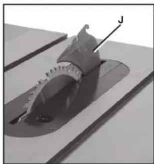
natural_image
Close-up of a mechanical component with a labeled feature 'J' (no readable text or symbols beyond the label)FIG. 27
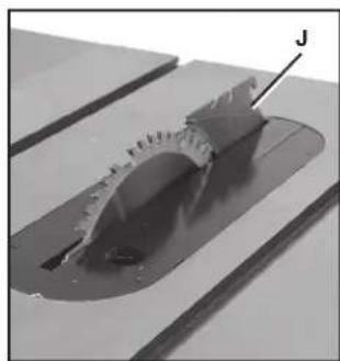
natural_image
Close-up of a mechanical component with a curved cutaway view and a labeled arrow pointing to a feature (no text or symbols visible)FIG. 28
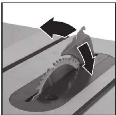
natural_image
Close-up of a mechanical component with arrows indicating motion or force direction (no text or symbols)FIG. 28A
natural_image
Close-up of a mechanical device with dual rotary dials and control knobs (no visible text or symbols)FIG. 29
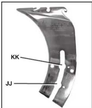
FIG. 30
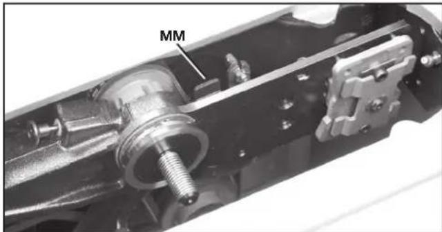
FIG. 31
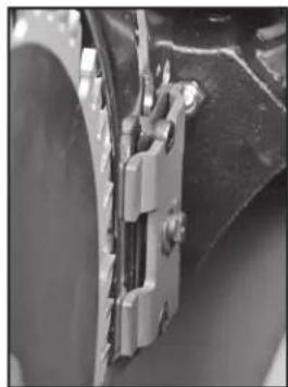
natural_image
Close-up of a mechanical bracket or clamp assembly (no visible text or symbols)FIG. 31A
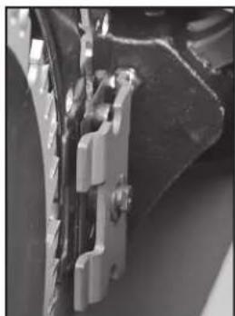
natural_image
Close-up of mechanical components with metallic brackets and connectors (no visible text or symbols)FIG. 31B
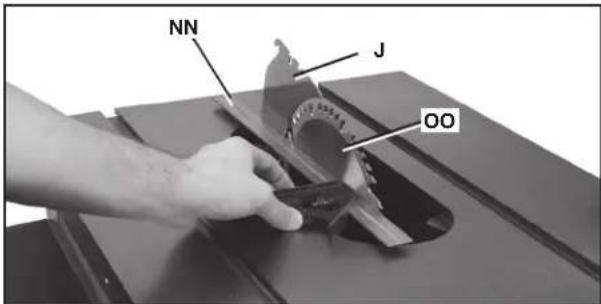
FIG. 32
CÓMO ALINEAR EL HENDEDOR CON LA HOJA
FIG. 33
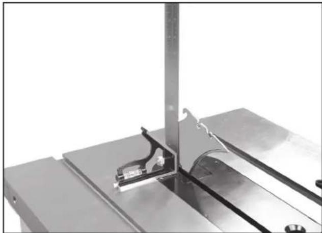
natural_image
Close-up of a metallic mechanical assembly with a curved component mounted on a base plate (no visible text or symbols)FIG. 34

natural_image
Close-up of a mechanical gear assembly with labeled component 'SS' (no other text or symbols visible)FIG. 35
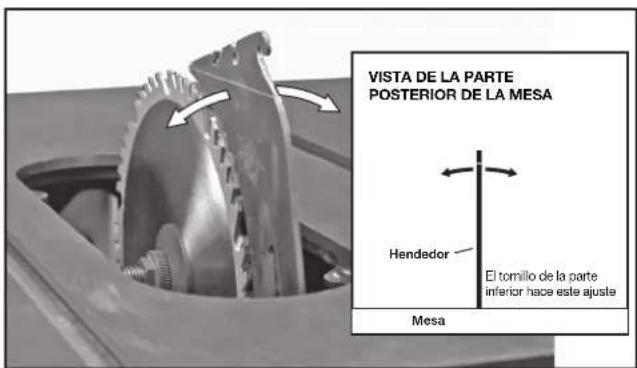
natural_image
Metallic curved bracket with two slots and a central hole, no visible text or symbolsFIG. 40
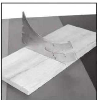
natural_image
3D rendered diagram of a curved metallic object on a flat surface, no text or symbols visibleFIG. 41
natural_image
Close-up of a mechanical tool interacting with a circular saw blade and metal bracket (no visible text or symbols)FIG. 46
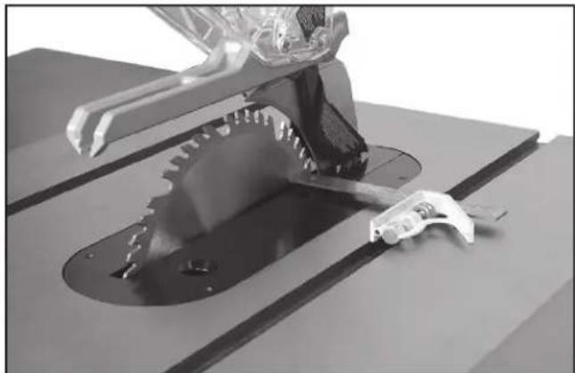
natural_image
3D rendered mechanical assembly with gear and tool components (no visible text or symbols)FIG. 47
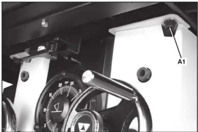
natural_image
Close-up of a mechanical device with a dial and labeled component A1 (no readable text or symbols beyond label)FIG. 48
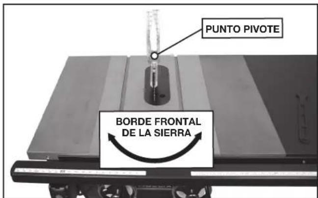
FIG. 49
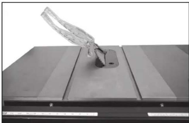
natural_image
Close-up of a transparent plastic object mounted on a metal base, no visible text or symbolsFIG. 50
natural_image
Close-up of a hand holding a transparent plastic car component, with no visible text or symbols.FIG. 54C
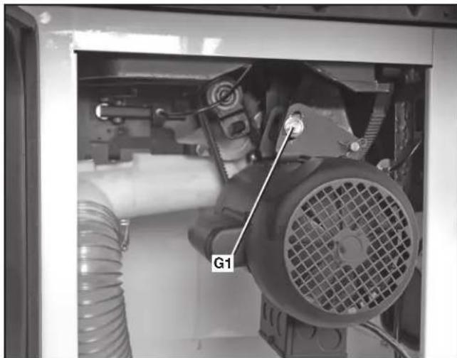
natural_image
Interior view of a mechanical assembly with visible components and a labeled component 'G1' (no readable text or symbols beyond label)FIG. 54A
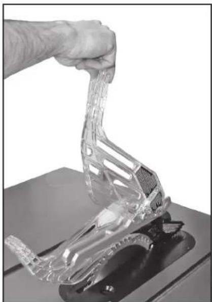
natural_image
Hand holding a transparent plastic mechanical component on a workbench (no text or symbols visible)FIG. 54B
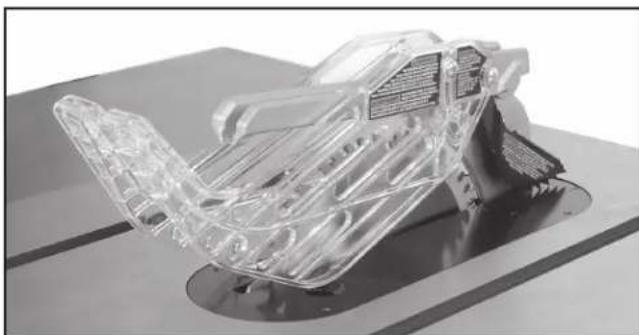
natural_image
3D cutaway view of a transparent plastic car chassis on a workbench (no visible text or symbols)FIG. 54D
UTILIZAR LA MAQUINA
REBOTE
natural_image
Person operating a robotic arm on a wooden cutting board in a workshop (no visible text or symbols)FIG. 55
natural_image
Person operating a robotic arm on a wooden table, with labeled component B (no visible text or symbols)FIG. 56
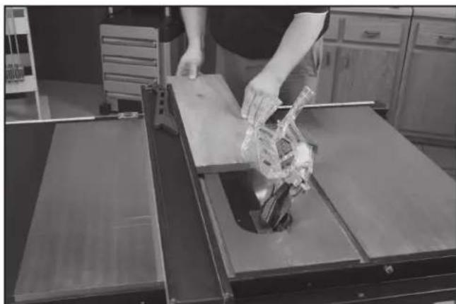
natural_image
Person handling a plastic bag over a wooden cutting board in a kitchen setting (no visible text or symbols)FIG. 57
natural_image
Person operating a vehicle chassis on a workbench, handling a transparent plastic car (no visible text or symbols)FIG. 58
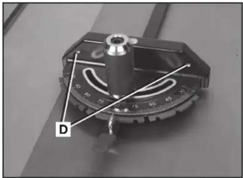
FIG. 59
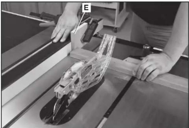
natural_image
Person operating a mechanical assembly with a transparent frame and tool, no visible text or symbolsFIG. 60
CORTE TRANSVERSAL CON BISEL
natural_image
Person using a cutting tool on a wooden cutting board with a transparent mechanical component nearby (no visible text or symbols)FIG. 61
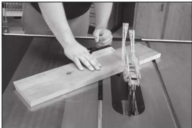
natural_image
Person using a wooden cutting machine to cut a wooden plank, no visible text or symbolsFIG. 62
natural_image
Mechanical assembly with a cylindrical component mounted on a base, no visible text or symbols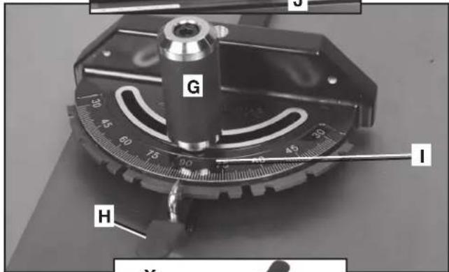
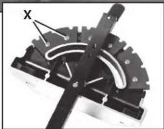
natural_image
Mechanical component with gear and lever mechanism (no visible text or symbols)FIG. 63
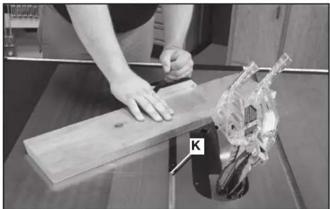
natural_image
Person using a wooden board to cut a mechanical component, with a transparent mechanical part labeled 'K' visible (no text or symbols on the main subject)FIG. 64
natural_image
Two views of a mechanical component: one with labeled part 'L' and the other showing internal structure (no text or symbols beyond labels)FIG. 65
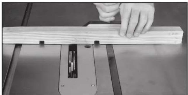
natural_image
Close-up of a hand using a wooden cutting machine to work on a wooden plank (no text or symbols visible)FIG. 66
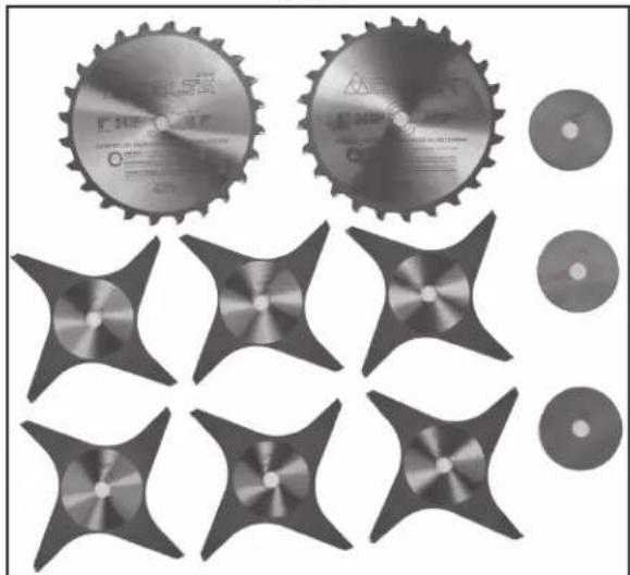
natural_image
Collection of industrial cutting gears and star-shaped components, no text or symbols visibleFIG. 67
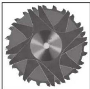
natural_image
Close-up of a metallic gear with visible teeth and central hub (no text or symbols)FIG. 68
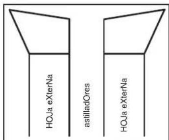
FIG. 69
USO DEL CABEZAL PORTACUCHILLA PARA MOLDURA
natural_image
Collection of mechanical parts including a circular component and a T-shaped tool, arranged in rows (no text or symbols visible)FIG. 71
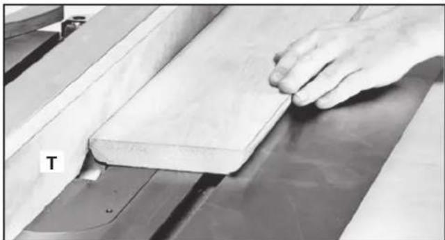
natural_image
Close-up of a hand pressing down on a wooden plank on a workbench (no visible text or symbols)FIG. 72
natural_image
Close-up of mechanical clamping components mounted on a metal frame, no visible text or symbolsFIG. 73
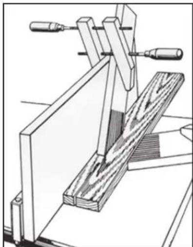
natural_image
Technical line drawing of a wooden clamp or clamping device with no visible text or symbolsFIG. 74
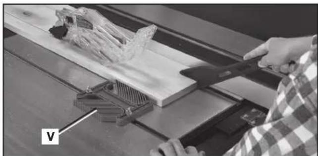
natural_image
Person using a 3D tool to cut a wooden plank with a plastic structure, no visible text or symbolsFIG. 76
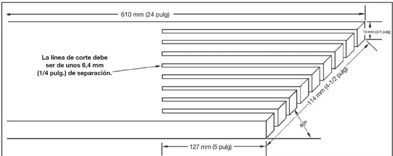
other
| Dimension | Value | | ----------------- | ----------- | | Height (mm) | 610 | | Width (meters) | 24 | | Height (cm) | 19 | | Width (cm) | 3/4 | | Height (mm) | 114 | | Width (mm) | 4-1/2 | | Height (cm) | 60 | | Width (cm) | 5 | | Height (mm) | 127 |FIG. 75
natural_image
Black plastic tool blade with cutouts and a pointed tip (no text or symbols visible)FIG. 78
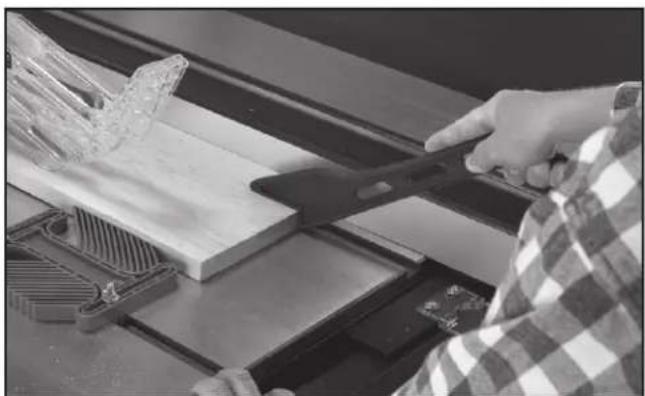
natural_image
Person using a tool on a wooden cutting machine, no visible text or symbolsFIG. 79
natural_image
Technical line drawing of a mechanical component with gear and circular feature (no text or symbols)FIG. 81
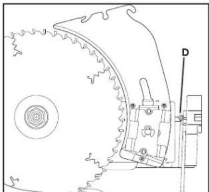
natural_image
Technical line drawing of a mechanical component with gear and mounting bracket (no text or symbols)FIG. 82
natural_image
Interior view of a mechanical assembly with labeled components J and K (no readable text or symbols beyond labels)FIG. 86
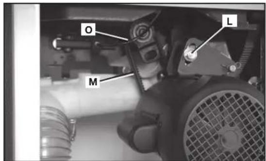
FIG. 87
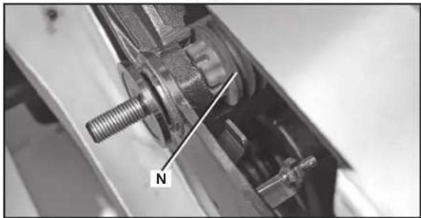
natural_image
Close-up of a mechanical assembly with a threaded bolt and labeled component 'N' (no readable text or symbols beyond the label)FIG. 88
SERVICIO
PIEZAS DE REPUESTO
Av. La Paz #1779 - Col.
Americana Sector Juárez (33) 3825 6978
MEXICO, D.F.
Eje Central Lázaro Cárdenas No. 18
Local D, Col. Obrera (55) 5588 9377
MERIDA, YUC
Calle 63 #459-A - Col. Centro (999) 928 5038
MONTERREY, N.L.
Av. Francisco I. Madero No.831 - Col. Centro (818) 8375 2313
PUEBLA, PUE
17 Norte #205 - Col. Centro (222) 246 3714
QUERETARO, QRO
Av. Madero 139 Pte. - Col. Centro (442) 2 17 63 14
SAN LUIS POTOSI, SLP
BOSQUES DE CIDROS, ACCESO RADIATAS NO.42
2 BY 4®, 890™, Air America®, AIRBOSS™, Auto-Set®, B.O.S.S.®, Bammer®, Biesemeyer®, Builders Saw®, Charge Air®, Charge Air Pro®, CONTRACTOR SUPERDUTY®, Contractor's Saw®, DELTA®, DELTA®, DELTA Industrial®, DELTA MACHINERY & DESIGN™, DELTA Shopmaster and Design®, DELTA X5®, DELTAcraft®, DELTAGRAM®, Do It. Feel It.®, DUAL LASERLOC AND DESIGN®, EASY AIR®, EASY AIR TO GO™, ENDURADIAMOND®, Ex-Cell®, Front Bevel Lock®, Get Yours While the Sun Shines®, Grip to Fit®, GRIPVAC™, GTF®, HICKORY WOODWORKING®, Homecraft®, HP FRAMER HIGH PRESSURE®, IMPACT SERIES™, Innovation That Works®, Jet-Lock®, Job Boss®, Kickstand®, LASERLOC®, LONG-LASTING WORK LIFE®, MAX FORCE™, MAX LIFE®, Micro-Set®, Midi-Lathe®, Monsoon®, MONSTER-CARBIDE™, Network®, OLDHAM®, Omnijig®, PC EDGE®, Performance Crew™, Performance Gear®, Pocket Cutter®, Porta-Band®, Porta-Plane®, Porter Cable®, Porter-Cable Professional Power Tools®, Powerback®, POZI-STOP™, Pressure Wave®, PRO 4000®, Proair®, Quicksand and Design®, Quickset II®, QUIET DRIVE TECHNOLOGY™, QUIET DRIVE TECHNOLOGY AND DESIGN™, Quik-Change®, QUIK-TILT®, RAPID-RELEASE™, RAZOR®, Redefining Performance®, Riptide®, Safe Guard II®, Sand Trap and Design®, Sanding Center®, Saw Boss®, Shop Boss®, Sidekick®, Site Boss®, Speed-Bloc®, Speedmatic®, Stair Ease®, Steel Driver Series®, SUPERDUTY®, T4 & DESIGN®, THE AMERICAN WOODSHOP®, THE PROFESSIONAL EDGE®, Thin-Line®, Tiger Saw®, TIGERCLAW®, TIGERCLAW AND DESIGN®, Torq-Buster®, TRU-MATCH®, T-Square®, Twinlaser®, Unifence®, Uniguard®, UNIRIP®, UNISAW®, UNITED STATES SAW®, Veri-Set®, Versa-Feeder®, VIPER®, VT™, VT RAZORT™, Water Driver®, WATER VROOM®, Waveform®, Whisper Series®, X5®, YOUR ACHIEVEMENT. OUR TOOLS.®
Trademarks noted with ® are registered in the United States Patent and Trademark Office and may also be registered in other countries. Other trademarks may apply. • Les marques de commerce suivies du symbole ® sont enregistrées auprès du United States Patent and Trademark Office et peuvent être enregistrées dans d'autres pays. D'autres marques de commerce peuvent également être applicables. • Las marcas comerciales con el símbolo ® están registradas en la Oficina de patentes y marcas comerciales de Estados Unidos (United States Patent and Trademark Office), y también pueden estar registradas en otros países. Posiblemente se apliquen otras marcas comerciales registradas.

DELTA Machinery, PO Box 2468, Jackson, TN 38302-2468
(800) 223-7278 - U.S. • (800) 463-3582 - CANADA
www.deltaportercable.com
Copyright © 2009, 2010 DELTA
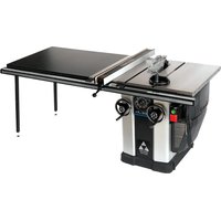
- 10" LEFT TILTING UNISAW®
- IMPORTANT SAFETY INSTRUCTIONS
- SAVE THESE INSTRUCTIONS!
- SAFETY GUIDELINES - DEFINITIONS
- GENERAL SAFETY RULES
- ⚠ WARNING: Failure to follow these rules may result in serious personal injury.
- ADDITIONAL SPECIFIC SAFETY RULES
- WARNING: Failure to follow these rules may result in serious personal injury.
- SAVE THESE INSTRUCTIONS.
- Refer to them often and use them to instruct others.
- TERMINOLOGY
- SAW BLADE GUARD ASSEMBLY, ANTI-KICKBACK ASSEMBLY AND RIVING KNIFE
- MAKING A PUSH STICK
- KICKBACKS
- How to avoid them and protect yourself from possible injury
- SAVE THESE INSTRUCTIONS
- POWER CONNECTIONS
- FOR THREE HORSEPOWER, SINGLE PHASE UNITS
- FOR FIVE HORSEPOWER, SINGLE PHASE UNITS
- MOTOR SPECIFICATIONS
- GROUNDING INSTRUCTIONS
- All grounded, cord-connected machines:
- EXTENSION CORDS
- FUNCTIONAL DESCRIPTION
- FOREWORD
- CARTON CONTENTS
- UNPACKING AND CLEANING
- REMOVE SHIPPING FOAM
- ASSEMBLY
- ASSEMBLY TOOLS REQUIRED
- ASSEMBLY TIME ESTIMATE
- SECURING SAW TO A PERMANENT LOCATION
- EXTENSION WINGS
- SWITCH
- ANTI-KICKBACK, RIVING KNIFE AND BLADE GUARD ASSEMBLIES
- ANTI-KICKBACK ASSEMBLY
- BLADE GUARD ASSEMBLY
- To remove the blade guard assembly:
- MITER GAUGE ASSEMBLY
- MITER GAUGE STORAGE
- DUST PORT REDUCER
- FENCE SYSTEM
- OPERATION
- OPERATIONAL CONTROLS AND ADJUSTMENTS
- STARTING AND STOPPING THE SAW
- LOCKING SWITCH IN THE "OFF" POSITION
- OVERLOAD PROTECTION
- RAISING AND LOWERING THE BLADE
- TILTING THE BLADE
- THROAT PLATE ADJUSTMENT
- RIVING KNIFE OPERATION AND ADJUSTMENT
- POSITIONING THE RIVING KNIFE
- FRONT-RELEASE (PRIMARY METHOD)
- RIVING KNIFE RELEASE LEVER (ALTERNATIVE METHOD)
- ALIGNING RIVING KNIFE TO BLADE
- SELECTING SAW BLADES
- RIVING KNIFE SELECTION
- MM THICK KNIFE:
- MM THICK KNIFE:
- ADJUSTING 0° AND 45° POSITIVE STOPS
- ADJUSTING BLADE TILT SCALE
- ADJUSTING MITER SLOT PARALLEL TO BLADE
- TAKING SLACK OUT OF RIVING KNIFE RELEASE CABLE
- ALIGNING THE RIP FENCE AND TABLE BOARD
- CHANGING THE SAW BLADE
- MAXIMUM BLADE HEIGHT ADJUSTMENT
- ADJUSTING BELT TENSION
- MACHINE USE
- KICKBACK
- MAKING CUTS
- RIPPING
- ⚠ WARNING: Keep hands clear of the blade
- RIPPING SMALL PIECES
- BEVEL RIPPING
- CROSSCUTTING
- BEVEL CROSSCUTTING
- MITERING
- COMPOUND MITERING
- USING AN ACCESSORY DADO HEAD
- HOW TO USE A MOLDING CUTTERHEAD
- USING AUXILIARY WOOD FACING
- CONSTRUCTING AND USING A FEATHERBOARD
- CONSTRUCTING AND USING A PUSH STICK
- TROUBLESHOOTING
- MAINTENANCE
- KEEP MACHINE CLEAN
- FAILURE TO START
- LUBRICATION & RUST PROTECTION
- REPLACING BELTS
- SERVICE
- REPLACEMENT PARTS
- FREE WARNING LABEL REPLACEMENT
- WARNING
- ADVERTENCIA
- WARRANTY
- Five Year Limited New Product Warranty
- CONSTRUCTING A PUSH STICK
- LES INSTRUCTIONS IMPORTANTES DE SURETE
- DÉSEMBALLAGE ET NETTOYAGE
- ASSEMBLAGE
- INTERRUPTEUR
- ENSEMBLE PROTÈGE-LAME
- RANGEMENT DU GUIDE D'ONGLET
- FONCTIONNEMENT
- L'OPERATION CONTROLE DE LE ET LES AJUSTEMENT
- AVERTISSEMENT :
- ATTENTION:
- ALIGNEMENT DU COUTEAU SÉPARATEUR SUR LA LAME
- COUTEAU SÉPARATEUR DE 2,7 mm (0.106 po) D'ÉPAISSEUR:
- COUTEAU SÉPARATEUR DE 2,8 mm (0.110 po) D'ÉPAISSEUR:
- TENSION DU CÂBLE DE DÉGAGEMENT DU COUTEAU SÉPARATEUR
- UTILISATION DE LA MACHINE
- REBONDS
- ONGLET
- FABRICATION ET UTILISATION D'UN POUSSOIR
- DEPANNAGE
- DÉMARRAGE IMPOSSIBLE
- PIÈCES DE RECHANGE
- DESEMPAQUETADO Y LIMPIEZA
- ENSAMBLAJE
- ADVERTENCIA:
- INTERRUPTOR
- ENSAMBLAJE DEL PROTECTOR DE LA HOJA
- ALMACENAMIENTO DEL CALIBRADOR DE INGLETE
- OPERACIÓN
- CÓMO LEVANTAR Y BAJAR LA HOJA
- CÓMO INCLINAR LA HOJA
- CÓMO ALINEAR EL HENDEDOR CON LA HOJA
- UTILIZAR LA MAQUINA
- REBOTE
- CORTE TRANSVERSAL CON BISEL
- USO DEL CABEZAL PORTACUCHILLA PARA MOLDURA
- SERVICIO
- PIEZAS DE REPUESTO
Brand : DELTA
Model : UNISAW 36‑L352
Category : Table saw